Table of Contents
Advertisement
Quick Links
Advertisement
Table of Contents

Related Manuals for Dedicated Micros CamVu 720 Series

Summary of Contents for Dedicated Micros CamVu 720 Series
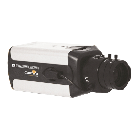
- Page 1 CamVu 720 Installation and Configuration Manual DM/CMVU720 DM/CMVU7200/N...
-
Page 2: Table Of Contents
Contents Important Safeguards ............... 5 Mounting External Domes .............. 14 Configuring the Unit ................ 19 System ................... 22 Display .................... 40 Camera ................... 45 Dome Settings ................46 ICR Settings ................... 59 Schedule ..................71 Alarm Settings ..................76 Network Settings ................88 Diagnostics ................... - Page 3 MULTIPLE, SIMULTANEOUS VIDEO STREAMS Dedicated Micros’ unique Visual Signal Processor (ViSP) allows the CamVu720 Series to transmit multiple simultaneous MPEG-4, H.264 and/ or JPEG images to any number of associated NetVu Connected devices for image viewing.
- Page 4 Features ■ High definition IP Camera - up to 2MP resolution ■ Available in static camera, internal mini-dome or Vandal Resistant Mini-dome options ■ Integrated Camera Recording and full enterprise video server within camera ■ Can form part of a Closed IPTV system ■...
-
Page 5: Components Supplied
If the camera utilises Power Over Ethernet, a separate PSU is not necessary (if power is available via the Ethernet connection). Alternatively if powering the unit over PoE using the supplied injector, a 48Vdc PSU that can supply 15W is required - DM/PSU/48V can be purchased separately from Dedicated Micros. -
Page 6: Important Safeguards
This section contains the regulatory declarations for the EU for the Unit Camera. This product is marked with the CE symbol and indicates compliance with all applicable Directives. A “Declaration of Conformity” is held at Dedicated Micros Ltd, 1200 Daresbury Park, Daresbury, Cheshire WA4 4HS www.dedicatedmicros.com... -
Page 7: Rf Interference Warning
Hereby, Dedicated Micros LTD, declares that this Unit Camera is in compliance with the essential requirements and other relevant provisions of Directive 95/5/EC. Marking by the symbol CE indicates compliance of this Dedicated Micros product to the Electromagnetic Compatibility Directive 89/336/EEC, and the Low Voltage Directive 73/23/EEC of the European Union. -
Page 8: Rear Connections
Installation Rear Connections The CamVu 720 features push fit connectors which house connections for 12VDC power. There is also a PoE capable RJ45 socket for connection to a suitable network point. The BNC video output connection is used in conjunction with a local monitor to focus the camera during installation and can also be used to display the camera’s current network settings. - Page 9 Connections Power Connections CamVu720 cameras are available in PoE plus AC/DC low voltage types. The voltage required to operate the camera is clearly marked on the rear panel of the camera. The power LED on the rear panel indicates that power is connected. Power over Ethernet The camera can be powered from any suitable PoE injector conforming to IEEE 802.3-2008.
-
Page 10: Lens Connections
The POE Injector cable is designed to enable the use of POE (Power over Ethernet) before a POE capable switch has been installed. It is installed alongside a suitable 48Vdc PSU that can supply 15W is required - DM/PSU/48V can be purchased separately from Dedicated Micros. Connection to DVR/NVR/Layer 3 Enhanced CCTV Switch Connection to suitable 48Vdc 15W PSU - (DM/PSU/48V) Ethernet cable connection to camera. - Page 11 Lenses Lens Setup Procedures Back Focus Adjustment The back focus adjustment is located at the front of the camera and is accessible from either the top or bottom of the case. To adjust the back focus: Loosen the two back focus mechanism locking screws (top and bottom of the camera). Turn the back focus ring anti-clockwise (when viewing the front of the camera) until the CMOS sensor assembly is as far away from the back of the lens as possible.
-
Page 12: Configuring The Unit
Configuring the Unit Using the Unit with Secure Closed IPTV 1) Connect the camera to a Closed IP Network switch using Cat5 network cable. The POE version of this camera will draw power from with the DM/NSW/CPP model switch, or with DM/NSW/CP model switch if connected to a POE injector and separate power supply. - Page 13 Accessing the Configuration Pages The unit is configured using the on-board configuration pages. To access these: Launch a web browser, preferably on a PC on the same subnet as the unit. 6.12 Type the IP address (or DNS name if there is no fixed IP address) of the unit into the address bar. If prompted, enter a username and password.
-
Page 14: System
System The menus under the System heading allow the unit’s core settings to be viewed, changed and the system software upgraded. The Attributes option displays details about the unit including the IP address, unit serial number, MAC address and software version. The Status page displays information about the unit’s operating condition, shows how long the unit has been operating and the reason for the last reset. - Page 15 Attributes This menu shows the general information about the unit including the version of software installed, the unit’s serial number and the allocated DHCP IP address. The system will display a warning if user accounts have not been set up. These can be eliminated by setting up accounts in ‘Display->User Accounts’.
- Page 16 Number of Cameras Shows the number of camera channels on the unit i.e 1 Global PPS Details the unit Global PPS (Pictures Per Second) recording rate. Video Storage Gbytes Highlights the available video storage capacity in Gigabytes. Video Standard Displays the video standard adopted by the unit i.e. PAL, NTSC. Software (Red) Links to the System Settings->Software details page Time/Date (Green)
-
Page 17: Unit Status
Status Unit Status This menu details information regarding the status of the unit, notably the total time the unit has been operating and the time since its last reset. Time since last reset Details the time since the unit was last reset. Total running time Details the total time the unit has been operational. - Page 18 About This page provides quick links to the pages required to fault find. System Information Opens the page. System Settings->System Software Revisions Opens the page. System Settings->Software General Information Opens the page (refer to General Information ‘General Information’ Record Details Opens the page (refer to Record Details...
- Page 19 About (Blue) Select to open the System->Status->About page. Refresh (Purple) Refreshes the information on the current page.
- Page 20 Network Security Logs The log files stored in the camera can be accessed from this page. Selected logs are displayed on the page below. Start Date Enter a start date to filter the security log entries Start Time Enter a start time to filter the security log entries End Date Enter an end date to filter the security log entries End Time...
- Page 21 Glossary This page provides quick reference to the technical terms used throughout the manuals and on the configuration pages, and allows alphabetical indexing and free text searching. Search (Red) Enter text into the search box and then click this button to find all related terms.
- Page 22 Logs The log files stored in the camera can be accessed from this page. Selected logs are displayed on the page below. About (Blue) Opens the page About Refresh (Purple) Refreshes the current page CamVu 720...
-
Page 23: Security Logs
Security Logs The network security logs, which show details of attempted intrusions over the network between the configured dates and times, can be displayed on this page. Refresh (Purple) Refreshes the information on the current page. - Page 24 Language This menu allows the system language to be set. Changing the System Language will effect all menu pages. If required, the language can also be changed for the current session only. System Language Select to change the system language setting. Reset (Red) Select to reset the unit.
-
Page 25: Time And Date
Time and Date This menu allows the time and date to be set on the unit. Required timezone information can also be established and the unit time synchronised to that of the PC being used to view the webpages. IMPORTANT: Not all options will be available when the unit is operating in Analogue mode. - Page 26 Note: It is recommended that an SNTP server is configured. Suitable networked SNTP servers can be found here: http://support.ntp.org/bin/view/Servers/NTPPoolServers. Alternatively most DHCP and DNS servers also run SNTP services. Contact your system administrator for further assistance. Note: The ‘SNTP Server’ option will not be available when the unit is operating in Analogue mode. PC Time Displays the system time of the PC currently being used to view the webpages.
-
Page 27: System Features
Features This menu enables the activation of system features such as Email Reporting. System (Red) Opens the page System Features Network (Green) Opens the page System Features Network (below) Video (Yellow) Opens the page System Features Video (below) Other (Blue) Opens the page System Features Other... - Page 28 ‘Network Settings-Remote Reporting’ for more information. Note: When de-selected here, the ‘Remote Reporting’ menu will no longer be displayed in the menu tree. Automatic FTP Download Select this option to enable automatic FTP downloads to upgrade the unit and/or the webpages, refer to ‘Network->FTP Download’ for more information.
-
Page 29: System Features Network
System Features Network Secondary Web Port If the default port setting for web serving has already been allocated, it is possible to configure a second port number i.e. the secondary web port can be set to 8000 if the default web port (80) is blocked by the network or firewall. -
Page 30: System Features Video
Refresh (Purple) Refreshes the information on the current page. System Features Video Detected Video Standard The unit automatically detects the video standard being used i.e. PAL/NTSC. Analogue Output Resolution Allows selection of the resolution, options are 704 x 576, 704 x 512 and 640 x 512 Deinterlace Filter Select this option to improve display clarity and minimise the comb effect... -
Page 31: System Features Other
Other (Blue) Select to open the System->Features->Other page Refresh (Purple) Refreshes the information on the current page. System Features Other Auto Update Web Variables This is used to enable/disable the configuration webpage auto update acceptance option which is displayed when the configuration webpage version has been updated. - Page 32 Maintain This menu allows the unit to be reset and a software upgrade to be performed via an inserted CD-R/ DVD-R or a connected USB device. Current unit settings can also be saved for future use and previously saved settings restored. Configuration Default (Green) Select to return the unit to its factory default settings.
- Page 33 IMPORTANT: To upgrade the unit, insert a media device containing relevant software upgrades and select ‘Reset‘. Note: For the latest software upgrades, please refer to the Dedicated Micros website: www.dedicatedmicros.com Reset (Red) Select to cycle the power to the unit.
- Page 34 Note: Changes this page will alter the ‘Default.C’ file. If you already have a custom PowerScript on your unit which uses Default.C, please contact Dedicated Micros Technical Support for guidance Tel: +44 (0) 845 600 9502 for further guidance. Reset (Red) Select to cycle the power to the unit.
-
Page 36: Display
Display The Display menu allows settings for the local viewing client to be established and user access to the system. IMPORTANT: The Display menu will not be available when the unit is operating in Analogue mode. The Viewer Defaults page allows the Viewer menu settings to be configured. The User Accounts page helps protect configuration procedures by limiting access to specific users via accounts and passwords. -
Page 37: Viewer Defaults
Viewer Defaults The units Viewer function allows remote users to simulate local operation over a network. This menu allows configuration of settings for the Viewer function, refer to ‘Operating The Viewer’ for more information regarding the Viewer. Default Image Format Images from cameras can be displayed in either JPEG or MPEG format. - Page 38 For example, if a local unit and a remote DVR are to be accessed, it is possible to set the Applet location for both DVRs as the local unit. If viewing the unit remotely, Dedicated Micros provide a remote applet located on the Dedicated Micros website (www.dedicatedmicros.com/ software_release/windows/viewer-applet.jar).
-
Page 39: User Accounts
User Accounts The unit can protect configuration, control FTP and viewing rights by limiting access via user names and passwords. Account Types The available account types for which users and passwords can be assigned privileges are: • Admin FTP Assigning username and password requirements for the Admin FTP function will limit access to the unit via an FTP connection. - Page 40 Modify or Delete. IMPORTANT: If passwords are implemented and then forgotten, it is likely the unit will need to be returned to Dedicated Micros for unlocking. Add (Red) Highlight an administration feature i.e. Serial and select ‘Add’. Enter the new User Name and Password.
-
Page 41: Camera
Camera The Camera menus allow configuration of the camera setup, refer to the individual menus for further information. The Setup page allows the quick configuration the camera setup. The Iris Control page allows adjustments to settings of a DC drive lens when one is fitted. This is to allow for tolerances in manufacturers lenses. - Page 42 Setup This menu allows the configuration of local camera settings for the unit. Camera Title This title can be edited to allocate a name to the unit. This is displayed when the unit is accessed via NetVu ObserVer and is set when transmitting information to a Remote Video Response Centre (RVRC) Lens Select...
- Page 43 Exposure Level Sets the target exposure level that the electronic iris will try to attain. This can be used to adjust the brightness of the image. Flip Video Used to invert the image when the camera is mounted upside down. Mirror Video Select to ‘mirror’...
-
Page 44: Iris Control
Iris Control This menu is for advanced use only. It is factory set and should not require any alteration. Under normal operating conditions no adjustment is needed, however in certain circumstances benefits may be seen through minor adjustment for some DC drive lens. Iris Response This will change the speed at which the Iris will respond to changes in lighting conditions. -
Page 45: Icr Settings
ICR Settings The ICR Settings menus allow configuration of the unit’s record functions. ICR settings can be configured for normal operation, on alarm, by schedule and for set holiday and weekend periods. Selected video data can be saved and protected. Refer to the individual menus for further details. IMPORTANT: The ICR Settings menu will not be available when the unit is operating in Analog mode. - Page 46 Default The unit has a range of pre-defined configurations available. As standard the unit can record at 5pps MPEG4 and at a selected number of days. Alternatively the unit can be configured for 2pps JPEG recording on each camera or for MultiMode operation (note that this will result in the record duration being determined by the time period the unit is in alarm).
-
Page 47: Profile Record
Profile Record It is possible to set the unit recording configuration based on specific priorities. The Multi recording Mode feature offers the ability to set different recording rates, resolutions and compression formats across unset, set and override modes for each individual camera. By varying the quality, bit rate and file size of recorded images, the Multi function enables the recording capabilities of the unit to be greatly Mode... - Page 48 The accompanying dropdown list allows the number of frames captured per second to be set. The pictures per second (pps) option allows either 6, 5, 2, 1, 0.5, 0.25 or 0.1 pps to be recorded. Pictures can also be recorded at 1/4, 1/2 or 3/4 Real Time. To disable record, choose the ‘No Record’...
-
Page 49: Advanced Record
Advanced Record Menu View Switch to the Simple Profile Record menu. Note: When Advanced Record settings have been changed, it is not possible access the Simple Record menu until the newly configured Advanced Record settings have been applied. To do this, open the Record menu and select the ‘Save’... - Page 50 Size If JPEG is selected, the figure entered here will be the size of the JPEG transmitted (in Kbytes). JPEG file sizes can be configured within the range of 5-45Kbytes. Select the number of pictures recorded per second. If using MPEG4 recording, select the number of images recorded within a GOP (Group of Pictures).
-
Page 51: Protect Video
Protect Video This menu allows the unit to automatically protect and retain recorded data in the camera. Previously saved data can also be unprotected. Enter a start and end time and select ‘Reload List’ . All saved video files from the chosen time period will be shown in the upper textbox. These recorded ‘PAR’ files can then be selected and protected via their accompanying checkboxes and the Protect option. - Page 52 List From Date/Time This dialog box allows a search to be made within the protected video list starting from a specific Time and Date. List To Date/Time This dialog box allows a search within the protected video list to conclude at a specific Time and Date. Unprot all (Red) Select to unprotect all recorded video from the list Protect (Green)
- Page 53 This menu allows configuration of the units ATA over Ethernet (AoE) function. AoE is a network protocol designed for simple high-performance access of storage devices over Ethernet networks. Importantly the external storage device must be located on the same network as the unit. AoE does not rely on network layers such as IP and TCP, making it non routable i.e.
-
Page 54: Video Storage
Video Storage The Video Storage Allocation table displays drives that are available for video recording. Entries with the prefix ‘/HDD0’ indicate the units local hard drive (if installed), entries prefixed by ‘/udd0’ are recordable media connected to the unit via USB sockets (if fitted), an entry prefixed by ‘/mdd’ are installed SD cards. Device Entries with the prefix ‘/HDDx’... - Page 55 Clear Video (Blue) Wipes the video from the drive to disable playback. Refresh (Purple) Refreshes the current page To format additional Video Storage Plug a USB storage device into one of the available USB ports and click the purple Refresh button.
- Page 56 The system displays a confirmation box to ensure the correct device has been selected. Click OK to confirm, then reboot the system. Once the power has cycled, the system will build the required PAR files ready for recording to commence, progress will be displayed in the Feedback column.
-
Page 57: Schedule
Schedule This menu allows the Timer Function names to be configured. The Timer Function enables the unit to automatically be put into set/unset mode at specific times on specific days. This can help reduce unnecessary alarm triggers. The mode can be set by the DVR that the camera is connected to. When the unit is in Set or Unset mode, combine with different recording qualities and rates under normal and alarm conditions for a high degree of control in a range of situations. - Page 58 Setup This menu allows the Schedule function to be configured. This enables the unit to automatically be put into set/unset mode at specific times on specific days. This can help reduce unnecessary alarm triggers. Combining when the unit is in Set or Unset mode with different recording qualities and rates under normal and alarm conditions gives a high degree of control in a range of situations.
- Page 59 Note: The arrow button displayed next to each textbox allows settings to be replicated for those cameras listed below. This will only affect the adjacent option i.e. Mode arrow will replicate the Mode setting to all cameras below the clicked arrow. Note: To disable one day, set both times to 00.00.
- Page 60 RVRC This menu allows a user to temporarily switch the unit’s system state into set/unset/override mode. The user will be required to enter their name and also the intended override duration. The action will be logged. Note: Refer to the Schedule menu for details of how to configure Set, Unset and Override modes: Record Settings->Schedule.
- Page 61 Override duration (minutes) Enter a time period for the override procedure. After this time period, the system state will return to that configured via the Schedule menu (for the current time). Enter Your Name Enter your recognised user name. This will be logged. Force UNSET(Green) Select to switch to Unset mode.
-
Page 62: Alarm Settings
Alarm Settings The Alarm Settings menus allow configuration of the unit’s alarm functionality. Individual alarm inputs and alarm zones can be configured. The Zone Input page enables the configuration of alarm zones. Up to 32 separate alarm zones can be created. -
Page 63: Zone Inputs
Zone Inputs This menu allows the configuration of established alarm zones. A single or multiple trigger can be used to generate an alarm. It is possible to allocate up to 32 alarm zones to carry out a combination of actions. Use these options in conjunction with the Zone Actions menu. - Page 64 Alarm Protect sec. This is the minimum time period in seconds (from the start of the alarm) that is protected from being overwritten. This time will include the alarm trigger, the pulse extension and any post alarm recording. It will not include pre-alarm images.
- Page 65 Alarm in (Blue) Select to open the Alarm->Inputs menu Refresh (Purple) Refreshes the information on the current page...
-
Page 66: Zone Actions
Zone Actions This menu allows actions to be allocated to individual alarm zones; Primary and Secondary cameras can be allocated to the zone and actions undertaken following alarm activation. This page should be configured in conjunction with the Zone Inputs menu. Zone Select a zone (alarm) to configure. - Page 67 E-mail Image If this option is selected, a JPEG will be added to the reporting e-mail (if E-mail Reporting is selected). VMD/Activity Inhibit Select to inhibit (ignore) the VMD/Activity detection feature. for further information, refer to ‘Alarm Settings->Activity Setup’. E-mail Reporting The unit can send an e-mail when an alarm is detected.
-
Page 68: Alarm Response
Alarm Response This menu enables response configuration following activity trigger on the camera channel. VMD Pulse Extension The pulse extension extends the trigger period to avoid double triggers of VMD occurring, i.e. If a second incident of VMD is received, after the first alarm is finished but within this period, the unit will not create a new event. - Page 69 Alarm Reporting This must be enabled for the unit to automatically connect on alarm. Alarm 24hr This will ensure that Activity Detection is permanently enabled on this camera channel. Add Still Image This will record a still image of the trigger along with the standard recording.
- Page 70 Activity The unit supports Activity Detection to enable the camera to automatically detect any movement/changes within the video scene; this can trigger a number of operations such as FTP alarm notification and an increase in recording rate. A still image of the selected camera will be shown in the Grid Editor screen. To establish an Activity zone, edit the cells displayed across the image.
-
Page 71: Vmd Configuration
VMD Configuration The unit supports VMD (Video Motion Detection) on all video inputs and allows cameras to automatically detect if there is any movement/changes within the video scene. Note: Video Motion Detection enables a greater degree of control over detection settings and configuration than the Activity Setup function. - Page 72 Mode The zone mode controls when the reference image is taken for triggering VMD. The options are: Normal - The reference image is updated approximately every second. This will only allow small changes in the scene without triggering. Last trigger - The reference image is only updated when the VMD is triggered and is best used under controlled lighting, i.e so there are no false triggers due to...
-
Page 73: Network Settings
Network Settings The Network Settings menus allow configuration of the unit’s network functionality. Key network settings can be established such as ‘fixing’ the unit’s IP address and maximum transmission rate. Email, remote reporting on alarm and FTP download can also be configured. Refer to the individual menus for further details. - Page 74 Network This menu allows network settings to be configured if required. The unit is DNS compliant, and can be referenced on the network using the configured server name (or serial number) if a DNS server is available . Server Name This field can be edited to allocate a name to the unit.
- Page 75 Tip: Use DHCP to locate a free IP address, then fix the unit IP address to the free one by entering the details into the IP address, subnet and gateway fields. This shows the maximum transmission speed for the network type Max Transmission Rate kbits/sec being used.
-
Page 76: Live Trans
Live Trans The unit transmits live images using JPEG or MPEG formats. The NetVu ObserVer remote viewing software will use the settings configured on this page as the defaults for JPEG & MPEG; High, Medium and Low settings. Filter by This will filter the camera category being edited. - Page 77 IMPORTANT: When ‘Filter by Turbo mode’ as been selected; all High LAN options will be auto- configured to match the profile record settings allowing for maximum record performance. High LAN will no longer be available for configuration of local analogue cameras or third party IP cameras.
- Page 78 Multicast The Multicast page allows video from the unit’s camera inputs to be forwarded to a port address, enabling multiple viewers to view live data using a suitable media player without the need to directly connect to the unit. In multi viewing scenarios, the demands on the unit are significantly reduced, improving overall performance.
- Page 79 Multicast port Following configuration of the IP address, configure the port address. The address will default to 1234. Multicast Method Select the multicast forwarding method. Select from ‘SAP’ (to use session announcement protocol operation), ‘HTTP’ (to use cgi control operation) or ‘SAP+HTTP’ (both methods used simultaneously). Enable Tick this option to enable multicast.
- Page 80 E-mail The unit can automatically transmit an email to an SMTP server under numerous conditions i.e. on start up, on receipt of an alarm, camera failure etc. This allows the unit to be installed in unmanned applications where a Remote Video Response Centre (or Manager etc.) would be notified by email if any of these conditions occur.
- Page 81 Sender Email These optional fields indicate the source of the email notification. If the fields are left blank the unit will use the system name to create a sender name. Sender Display Name This is the sender name that will be shown in the email name field. Send on Startup Select to send email notification on startup.
-
Page 82: Remote Reporting
Remote Reporting This menu allows configuration of the settings to enable the unit to report to a Remote Video Receiving Centre (RVRC) following alarm activation. Note: This menu will only be displayed if ‘Remote Reporting’ is selected in the System -> Features -> System menu. Primary Hostname This is the IP address or URL of the initial host that the unit will transmit an alarm message to. - Page 83 Alarm Server ref. ID This is the reference name/ID that will be presented to the RVRC viewing application. It should therefore have some significance to the Operator. Remote Alarm Reporting This must be enabled for the unit to automatically connect on alarm. Remote Cam Fail Reporting Enabling this option ensures the unit reports camera failure on any of the inputs to the RVRC.
-
Page 84: Web Cam
Web Cam Any of the video inputs on the unit can be made available for transmission to a webserver via a designated webcam server. These images can then be incorporated into a web page and accessed via a standard web browser. Note: This menu will only be displayed if ‘Webcam Support’... - Page 85 Password If it is necessary to use an authentication process to access the webcam server, enter the relevant password here. Update Interval This is howoften the unit transmits images to the web server. Select Camera Input This allows individual video inputs to be enabled for uploading to the webcam server.
-
Page 86: Ftp Download
FTP Download The unit can archive images to a central FTP (File Transfer Protocol) server. This could be on receipt of an alarm, activation of the Activity Detection or at a scheduled time to backup recorded video. Using FTP in a multi-unit application ensures that all files are stored in one central location for each of the units, offering efficient file management and easy review capabilities. - Page 87 Username If it is necessary to use an authentication process to access the FTP server, enter the relevant username here. Password If it is necessary to use an authentication process to access the FTP server, enter the relevant password here. Download options Select one of the following options from the drop down menu: On Connection This will automatically start the Archive download when...
- Page 88 Firewall This menu allows the user to block access to the unit via specific network port(s). Enable Ping Response Enabling this option will allow an external client to receive a response when attempting to ‘ping’ the unit. Disabling this option will make the unit less visible on the network.
- Page 89 Connections This page shows the IP addresses of users connected to this unit. It is for information only and cannot be edited or configured. Refresh (Purple) Refreshes the current page...
- Page 90 Refer to the individual menus for further details. The unit is AnalyticsCapable. Please call Dedicated Micros on + 44 (0) 845 600 9500 for further information on our range of Analytics based solutions.
- Page 91 Features Dedicated Micros has created a range of analytics components and solutions designed to work with AnalyticsCapable products. The range of applications include: Automatic Number Plate Recognition (ANPR), Object Left and Removed, Access Control, People Counting and Perimeter Protection. •...
-
Page 92: Activate New Feature
Features System Code This code must be provided to the Dedicated Micros Customer Services team (Tel +44 (0) 845 600 9501) to obtain your Activation code. On receipt of this information, DM will provide you with your Activation code. - Page 93 License Key Enter the License key details here. The License key will be provided by Dedicated Micros Customer Services team. Activation Code Enter the Activation Code details here. Note: Both the License Key and Activation Code are case sensitive. Be careful to differentiate between number ‘0’...
-
Page 94: Text In Image
Text In Image It is possible to integrate the unit into a system were text information can be stored with relevant images for review. This would be most useful in a Retail or Finance application were text data originating from a cash register could be displayed in real time with the video images of the same Point of Sale. - Page 96 CamVu 720...
- Page 98 CamVu 720...
- Page 100 CamVu 720...
- Page 102 CamVu 720...
- Page 104 CamVu 720...
- Page 106 Keywords This menu allows a specific keyword received via the text stream to be configured and enabled as an event trigger. The ‘Enable Keyword’ function needs to be activated in the ‘Text in Image’ menu for this feature to operate. Text Keyword The unit can be configured to react to a keyword appearing in text data and treat it as an alarm zone input.
- Page 108 CamVu 720...
- Page 110 CamVu 720...
- Page 112 CamVu 720...
- Page 114 CamVu 720...
- Page 116 CamVu 720...
- Page 118 Archive The Archive menu allows the selection of the Archive media and initiation of the archive process. CamVu 720...
- Page 119 Archive This menu allows Event database information to be downloaded to an inserted DVD-R/CD-R or connected USB media device. Archive Media Select to archive to either a DVD-R/CD-R or USB media device. Start Date Enter a start date for the event download. Start Time Enter a start time for the event download.
-
Page 120: Diagnostics
Diagnostics The Diagnostics menus gives engineers the ability to quickly and accurately diagnose any problems with the unit. This menu will normally only be used on a Technical Support call. MPORTANT: The Diagnostic menu will not be available when the unit is operating in Analogue mode. CamVu 720... -
Page 121: Debug Parser
Debug Parser This menu allow detailed analysis of the debug output from the camera and maybe used to assist with fault finding. The debug can be filtered in order to isolate and highlight events that are of interest. View Defines whether the debug settings on the debug output will be displayed. -
Page 122: Event Search
Event Search The Event Search menu allows recorded event images to be quickly searched for and reviewed. The Search criteria can be limited to a specific date/time and/or individual cameras. IMPORTANT: The Event Search menu will not be available when the unit is operating in Analog mode. Note: Event Search will only be available in IP mode when the ‘Enable Event Search Page’... -
Page 123: Event Search Results
Event Search Results After selecting ‘Search’ (Red), a still image of each captured event (within the chosen search criteria) will be displayed. It may be necessary to scroll through the results pages to view all events. if the number of events exceeds the events displayed per page (configured in Event/Page). -
Page 124: Unit Operation
Unit Operation The unit can be operated via the Viewer menus and the enclosed IR Remote Control, the optional keyboard or with a USB mouse. They can also be viewed and accessed remotely via the webpages and the ‘Viewer’ menu option. CamVu 720... -
Page 125: Operating The Viewer
Operating the Viewer Navigation is via a colour coded softkey system. The coloured menu provides an intuitive approach to operator and installer use. The coloured keys on the IR Remote Control correspond to the menu options displayed on screen. Note: The screen images shown throughout this section are those displayed on a local monitor. -
Page 126: View Control
View Control The View Control page allows connected video inputs to be displayed full screen or in Quad/Multi way display format. Full Show currently selected camera full screen. Green Quad Displays four images on-screen, putting the currently selected camera in the top left segment of the four, and will increment all cameras by one if pressed again i.e. -
Page 127: Video Control
Video Control The Video Control page offers video playback functions i.e. play, pause, rewind and fast forward. Freezes current video display. Green << Rewinds current video. Yellow > Plays from current position. Blue >> Fast forwards video up to current recording position. -
Page 128: Selection Page
Selection Page The Selection page allows access to various image and event playback functions. Play Switches the selected camera(s) shown on screen into Play mode. Green Goto Opens the GoTo menu. Yellow Event Displays the Events menu. Blue Menu/Setup* Opens the Configuration menu pages. IMPORTANT: Selecting this option will exit the Viewer menus. - Page 129 Map Options The Map page allows access to available Cameras via the displayed hotspots. Blue Displays a map showing available cameras. If using the default numeric selector, choose a number to access the correspondingly numbered camera. The default numeric selector map can be replaced by a gif/ jpeg image.
-
Page 130: Ptz Program Option
PTZ Program Option The Program page allows preset settings for PTZ cameras to be established and an ‘Origin’ base position established for a camera. Note: This page will only be available for PTZ cameras. Preset If Preset positions have been established for the PTZ camera, select the Preset option and enter a preset number. -
Page 131: Program Page
Program Page The Program Menu page allows the PTZ configuration on the currently selected telemetry camera to be accessed and configured. Dome Select to display the Dome Menu page. Green Store Use to save the current view as a Preset for this camera. -
Page 132: Dome Menu Option
Dome Menu Option The Dome Menu page allows camera specific menus imbedded on the currently viewed Telemetry camera to be accessed and configured. Dome Menu Select to view camera specific sub-menus embedded on the Telemetry camera (if applicable). The camera specific menus will be overlaid across the screen. -
Page 133: Timeline Navigation
Timeline Navigation The Timeline Navigation page and the accompanying Video Timeline feature allows quick and easy investigation of recorded video data. The Goto button opens the initial Timeline Navigation page. Softkeys The coloured softkey options will change depending on the scale used to review the recorded images. -
Page 134: Video Timeline
Video Timeline The Video Timeline allows intuitive, rapid navigation within recorded video. To aid navigation, the timeline can be set to display periods ranging from 15 seconds to four weeks. The timeline can be clicked anywhere in the scale to instantly play recorded images from that point. Date/Time Display (Grey) Shows the currently selected date/time. -
Page 135: Change Scale
Change Scale Utilise the buttons shown below to change the scale. Note: The coloured softkey buttons can also be used to alter the scale, refer to “Softkey Guidance” for further details). Decrease Scale button (Blue) Decreases the scale of the displayed timeline by one step i.e. -
Page 136: Event List
Event List Alarms and activity detection, plus system Events i.e. camera fails, are tagged and stored in the Event List. Each Event is labelled with an event type (alarm, activity or system) and its time and date. To view any additional pages of Event data, use the Yellow/Blue Softkeys. If viewing locally, use the Up/Down Directional buttons to select a specific Event, press the OK button to display the full list. -
Page 137: Event Copy And Search Menu
Event Copy and Search Menu The Event Copy and Search menu allows events to be sent to the Copy menu via the Copy Option. All events currently held within the ‘Copy’ menu can be deleted via the ‘Clear All’ option. The ‘Filter option’ allows access to the ‘Filter Search’... -
Page 138: Filter Search Menu
Filter Search Menu When searching a large number of stored events, the Filter Search menu allows events to be filtered by time, camera channel and category. Filter Search Box From Time Select a start time for the Event filter. Events prior to this time will be ignored. - Page 139 From Date Select a start date for the Event filter. Events prior to this date will be ignored. Cameras Select which cameras are to be included within the Event search. A range of cameras can be selected by entering a hyphen between the first and last required camera i.e.1-8.
-
Page 140: Activity Search Menu
Activity Search Menu The Activity Search menu allows the search criteria to be further narrowed to only include events which have occured within specific segments of the camera view. Firstly, enter a start/end Time and Date, then select a camera channel. Use the Grid option to select a specific segment of the camera view. - Page 141 Cameras Select which camera to include within the Activity search. A range of cameras can be selected by entering a hyphen between the first and last required camera i.e.1-8. A selection of individual cameras can be chosen by entering a comma between each camera i.e.
-
Page 142: Activity Grid Menu
Activity Grid Menu The Activity Grid menu allows the event search criteria to be further narrowed to only display events which have occured within a segment of the camera view. A grid will be displayed across the image of the selected camera channel. Using the options outlined below, the grid can be configured to create activity zones within the image. - Page 143 IMPORTANT: The area (cells) highlighted yellow constitutes the activity detection zone. Any activity events occuring within the area created using the Start and and End points will be ignored. Note: Multiple zones can be created within the same camera view. Purple Finish Select to return to the Activity Search menu.
- Page 144 Selecting Video For Archiving Via The Archive option / Copy Event List When viewing the footage intended for download, enter a start and end point for archive purposes via the Mark (Red) button. The Copy Event List will be displayed detailing each added archive (based on the marked start and end point).
- Page 145 Yellow Archive Opens the Copy Menu. Blue Seq On/Off Select ‘Seq On’ to display images from all connected cameras in a sequential order. Purple Next Opens the Play menu for the currently displayed camera. Copy Menu Images and events can be copied to CD-R/DVD-R or USB Media for remote reviewing away from the unit (for evidential or monitoring purposes).
- Page 146 Archive Media Select the media device (USB or CD-R/DVD-R) for archive purposes. Include Viewer Application Select whether the application required to view archived data is included in the download. Used (Blue) Displays the space (as a percentage) already used on the chosen media device.
- Page 147 Spot Monitor / On-Screen Display (Local Monitor Only) This menu (only accessible via a local monitor) allows configuration of the camera output displayed on the spot monitor, plus enables all on-screen display text to be removed from the main monitor display Spot Select to change the camera currently displayed on the spot monitor.
- Page 148 Help Videos The Help Videos offer step by step guidance on performing some of the most common tasks required of the unit. Access the Video Help menu by selecting the Help (yellow) option on the View Menu. The Help videos are divided into six categories; each category containing relevant videos.
-
Page 149: Appendix A - Unit Specification
Directly configure from the associated NetVu Connected Video Server. In addition, when used within a Closed IPTV system, default settings (such as streaming rate, resolution, aspect ratio, telemetry, lens configuration etc.) can be automatically assigned to the camera INTEGRATION SPECIFICATIONS APPLICATION SUPPORT Browser: IE 5.5 / Firefox 2.0 and above Developer: Java via Dedicated Micros SDK... -
Page 150: Mounting Options
NETVU OBSERVER - SEAMLESS VIDEO MANAGEMENT Dedicated Micros NetVu ObserVer video management software allows seamless viewing and control of live and recorded images from any NetVu Connected product (IP or analogue) in a single interface. The ability to view multiple sites simultaneously makes management of any security installation efficient. -
Page 151: Appendix B - Status
Appendix D - Status Pages General Information This page gives an overview of the units current settings including IP address, connections to the camera, the locations that data is being read from and written to, and which recording profile is active. About (Blue) Opens the page... -
Page 152: Record Details
Record Details This page displays the configured recording settings for the unit. The current record mode being used by the unit can be found on the General Information page. About (Blue) Opens the page About Refresh (Purple) Refreshes the current page CamVu 720... -
Page 153: Camconfig Details
Camconfig Details This page displays the capabilities of the camera in terms of resolution and supported compression formats. This camera does not support audio, alarms, relay or lens de-warping so all these parameters return 0. About (Blue) Opens the page About Refresh (Purple) Refreshes the current page... - Page 154 Capabilities This information page shows the capability settings for the camera. These parameters determine how the camera performs and what options are available on the configuration pages. About (Blue) Opens the page About Refresh (Purple) Refreshes the current page CamVu 720...
-
Page 155: Ui Information
UI Information The UI page shows the settings stored in the camera which configure the user interface. About (Blue) Opens the page About Refresh (Purple) Refreshes the current page... -
Page 156: Profile Record Tables
Profile Record Tables This page shows the different settings available in the record configurations. The current default settings are indicated by crosses. About (Blue) Opens the page About Refresh (Purple) Refreshes the current page CamVu 720... - Page 157 Glossary This page provides quick reference to the technical terms used throughout the manuals and on the configuration pages, and allows alphabetical indexing and free text searching. Search (Red) Enter text into the search box and then click this button to find all related terms.
- Page 158 Index About ................27 Mounting Options ............13 Activity ................85 Multicast ............... 93 Activity Grid Menu ............122 Multiway Connector ............9 Activity Search Menu ..........120 Network ................ 89 Advanced Record ............63 Network Settings ............88 Alarm Response ............83 Operating the Viewer ..........
- Page 160 MI-I-CMV7/E1-0 www.dedicatedmicros.com...
Need help?
Do you have a question about the CamVu 720 Series and is the answer not in the manual?
Questions and answers