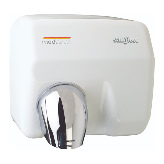
Summary of Contents for Saniflow E05A
- Page 1 IFS Ltd t/a Intelligent Hand Dryers UK www.intelligenthanddryers.com 0114 286 6394...
-
Page 2: Safety Regulations
Saniflow E05A hand dryer Safety regulations All installation, maintenance and repair tasks must be carried out by qualified technicians. Mediclinics remembers the importance of: 1. Becoming familiar with the equipment and carefully reading the user manual prior to operating. 2. Disconnecting power prior to beginning any repair or maintenance action. - Page 3 Removal of the casing Using a Saniflow security screwdriver, release the two screws in the lower part of the casing. The 2 screws have to be rotated clock wise to release the casing from the base plate. Carefully remove the casing...
- Page 4 Motor Characteristics - Type: Universal brush motor - Power: 250 W - Speed of rotation: 5,500 rpm - Class F - Incorporates a safety thermal limiter Maintenance of the motor As preventive maintenance, we recommend using a soft brush to remove dust and dirt on an annual or quarterly basis, depending on the dryer’s operating cycles.
- Page 5 Remove the brush from its location and replace it. Carry out the same procedure for the second motor brush. Replacement of the motor Unscrew the terminal block to release the power supply cables from the circuit board.
- Page 6 Carefully remove the clips that secure the electronic circuit board at the top. Carefully remove the clips that secure the electronic circuit board at the bottom.
- Page 7 Unscrew the motor cables from the electronic circuit board. Unscrew the screws that secure the volutes together.
- Page 8 Remove the left volute. (If the volute is difficult to remove, use a flathead screwdriver to help, taking care not to damage the plastic parts.) Remove the heating element for replacement.
- Page 9 Loosen the retainer screw that fixes the fan to the drive shaft. Remove the fan from the drive shaft.
- Page 10 Use pliers to release the springs securing the motor to the base. Remove the motor from its housing in the base and replace it.
-
Page 11: Heating Element
Heating element Characteristics - Type: Coiled wire heating element - Material: NiCr winding. 40; - Body: Mica - Power: 2.000 W. - Includes thermal limiter. Maintenance As preventive maintenance, we recommend using a soft brush to remove dust and dirt on an annual or quarterly basis, depending on the dryer’s operating cycles. Replacement of the heating elements Unscrew the terminal block to release the power supply cables from the circuit board. - Page 12 Carefully remove the clips that secure the electronic circuit board at the top. Carefully remove the clips that secure the electronic circuit board at the bottom.
- Page 13 Unscrew the heating element cables from the electronic circuit board. Unscrew the screws that secure the volutes together.
- Page 14 Remove the left volute. (If the volute is difficult to remove, use a flathead screwdriver to help, taking care not to damage the plastic parts.) Remove the heating element for replacement...
-
Page 15: Electronic Circuit Board
Electronic circuit board Characteristics Electronic sensor, with infrared beam. Detection distance adjustable by potentiometer (5-25 cm). Maintenance As preventive maintenance, we recommend using a soft brush to remove dust and dirt on an annual or quaterly basis, depending on the dryer’s operating cycles. - Page 16 Carefully remove the clips that secure the electronic circuit board at the top. Carefully remove the clips that secure the electronic circuit board at the bottom.
- Page 17 Unscrew the cables of the heating element and motor from the electronic circuit board. Replacement of the fan Unscrew the terminal block to release the power supply cables from the circuit board.
- Page 18 Carefully remove the clips that secure the electronic circuit board at the top. Carefully remove the clips that secure the electronic circuit board at the bottom.
- Page 19 Unscrew the heating element cables from the electronic circuit board. Unscrew the screws that secure the volutes together.
- Page 20 Remove the left volute. (If the volute is difficult to remove, use a flathead screwdriver to help, taking care not to damage the plastic parts.) Remove the heating element.
- Page 21 Loosen the retainer screw that fixes the fan to the drive shaft. Remove the fan from its position and replace it.


Need help?
Do you have a question about the E05A and is the answer not in the manual?
Questions and answers