
Subscribe to Our Youtube Channel
Related Manuals for Arbiter Systems 928A

Summary of Contents for Arbiter Systems 928A
- Page 1 MODEL 928A POWER SYSTEM MULTIMETER USER’S MANUAL ARBITER SYSTEMS, INC. PASO ROBLES, CALIFORNIA U.S.A.
- Page 2 Notice This manual is issued for reference only, at the convenience of Arbiter Systems. Every reasonable effort was made to verify that all contents were accurate as of the time of publication. Check with Arbiter Systems at the address below for any revisions made since the original date of publication.
- Page 3 Arbiter Systems under this warranty is limited to repair or replacement, at Arbiter Systems’ option, of any product found to be defective. Arbiter Systems shall have no liability under this warranty unless it receives written notice of any claimed defect, within the earlier of: •...
- Page 4 Arbiter Systems (whether by the substitution of non- approved parts or otherwise). The remedies provided herein are Buyer’s sole and exclusive remedies. In no event shall Arbiter Systems be liable for direct, indirect, incidental or consequential damages (including loss of profits), whether based on contract, tort, or other legal theory.
- Page 5 Table of Contents • Introduction • Getting Started • Operation • USB Communication • Functional Description • Specifications • Appendixes • Index © Copyright Arbiter Systems Incorporated November 1, 2005. All rights reserved. International copyright secured. Printed in USA PD0030900C...
-
Page 7: Table Of Contents
Versatile Inputs ............7 Voltage Terminals - 660 Vrms, max ......8 Current Terminals - 1.2 Arms, 1.2 Vrms, max ..... 9 928A Keys ..............10 MIN/MAX Key ............10 LCD - Display Control Key ........10 Function Keys - f1 - f6 ..........11... - Page 8 viii Contents Splash Screen ............11 Up and Down Arrows ..........11 MENU Key ..............12 Main Menu ............. 12 Firmware Version ........... 12 Phase Preference ............ 13 Frequency Preference ..........14 Auto Shutdown ............14 Flash Utilities Menu ..........15 Calibration Date Info ..........
- Page 9 Contents Operation ............27 Making Measurements ..........28 VI - Voltage and Current Measurement ..... 28 ØF - Phase / Frequency Measurement ....... 30 Phase Preferences ..........30 Phase Conventions ..........31 PWR - Active and Reactive Power ......32 PF - Power Factor &...
- Page 10 Download Mlink ............59 Installing USB Driver ..........60 FTDI Driver on Windows XP™ ......60 Installing Mlink ............61 Connecting the 928A to a Computer ......61 Startup - USB Connection ......... 62 Connecting ..............62 Mlink Main Window ............. 63 Available Functions ..........
- Page 11 Contents Functional Description ........73 User Interface ............73 Details ................ 73 Accessories ..............74 Current Measurement ..........74 Optional CT ............75 Voltage Measurement ..........75 Soft Carrying Case ..........75 USB Data Cable ............. 75 Specifications ..........76 Input ................
- Page 12 Appendix A. Keypad Definitions ....81 Primary Keys ............. 81 Secondary Keys ............83 Appendix B. CT Input Connector ....86 928A Current Input Connector ........86 CT Cable Connector ..........86 Appendix C. Phase Conventions ....87 Index ..............88...
-
Page 13: Introduction
Power System Multimeter is filled with great features to help you measure electrical power. Whether you are a new or experienced user, you should find the Model 928A easy to use and accurate. Three power sources include alkaline or NiMH AA cells, and a 6 V wall adapter for continuous use. -
Page 14: Safety Information
Caution: No Direct Current Input Do not connect a current signal directly to either Channel A or B. Always use a current-output or voltage-output CT when measuring current with the 928A. Measuring Safety Be sure to follow all precautions and safety information... -
Page 15: The Instrument Case
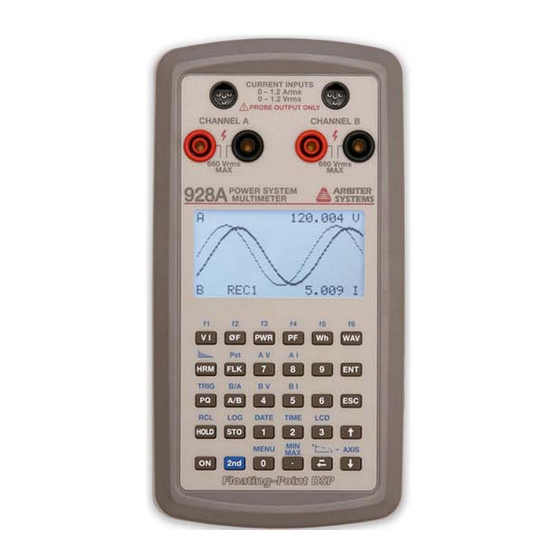
Therefore, use care to protect it from rain, spills or condensing environments. Caution: Water Damage The case is not waterproof. Subjecting the 928A to rain or a wet environment will most likely damage it. Display Using a 128x64 pixel display, the 928A can display all text and graphics necessary for operation. -
Page 16: Getting Started
Getting Started Getting Started Keyboard Operation Most of the keys on your 928A perform one primary and one secondary function. The primary function of any key is indicated by the characters on the face of the key, for example . The secondary functions are indicated above the key, for example (above the HOLD key). -
Page 17: Power On And Off
AC Power Adapter Included in the Model 928A Starter Kit is a power adapter (Arbiter part no. AP0009400) that provides power to the 928A and is suitable for continuous use. The power adapter is not designed to charge any batteries located in the battery compartment. -
Page 18: Operation
Batteries are disconnected when power adapter is connected to the Model 928A. Operation The power adapter supplies power to the 928A for normal operation. While using the power adapter, any batteries installed in the 928A are disconnected. To operate the 928A with the accessory power supply: 1. -
Page 19: Measurement Terminals
Getting Started Measurement Terminals The Model 928A has two identical sets of measurement terminals, called Channel A and Channel B, that accept either a voltage or a current. To measure a current, select one of the current input connectors at the top of the instru- ment. -
Page 20: Voltage Terminals - 660 Vrms, Max
Getting Started Voltage Terminals - 660 Vrms, max Two sets of voltage terminals allow you to directly connect voltages up to 660 Vrms, max. They may also be scaled for reading the primary voltage on a PT or transformer. These inputs are labeled “CHANNEL A”... -
Page 21: Current Terminals - 1.2 Arms, 1.2 Vrms, Max
The Current Input terminals for Channels A and B allow you to connect either a voltage- output CT or current-output CT to the 928A. A CT configu- ration screen allows you to setup CT values for both channels ahead of time, so they are ready to go at the job site. -
Page 22: 928A Keys
Caution – Max CT Input Level: Never apply any signal to Channel A or B current input terminals which is greater than 1.2 Arms or 1.2 Vrms. 928A Keys MIN/MAX Key Press the MIN/MAX key to cycle through various measure- ments, including the minimum, maximum, average and normal (active). -
Page 23: Function Keys - F1 - F6
Splash Screen When first powered on, the 928A will display an introduc- tory message that describes the 928A. Press any of the main measurement keys (e.g. ) to bypass the splash screen. Up and Down Arrows to step through values in configuration menus or for choosing specific records held in memory. -
Page 24: Menu Key
Getting Started MENU Key Use the MENU key to set up the functions, preferences and operating parameters of the 928A. Access these menus through the Main Menu, or in context. Main Menu 1. Press to open the main MENU MENU menu. -
Page 25: Phase Preference
Getting Started Phase Preference 1. From the Main Menu, highlight Phase Preference with the cursor and press to open the Phase Preference menu. 2. REFERENCE: Press to set the Reference to Channel A or B. Press to set it. 3. POLARITY: Press to set POLARITY as + or –... -
Page 26: Frequency Preference
Getting Started Frequency Preference 1. From the Main Menu, highlight Frequency Preference and press to open. 2. REFERENCE: Press access and change Reference value. 3. Press to access and change Frequency SETTING to either 50Hz or 60Hz. 3. Highlight <STOre And Exit> with the cursor and press to install the new value(s). -
Page 27: Flash Utilities Menu
Flash Utilities Menu Use the Flash Utilities Menu to manage flash memory in the 928A. In Full Mode, choose whether or not to overwrite stored values held in memory or to stop writing. Erase Flash? Allows you to delete all values held in flash. -
Page 28: Esc – Escape
Getting Started ESC – Escape Press to leave a specific menu or go back in key- strokes to the previous screen. For example, if you are viewing the Main Menu, press to leave the Main Menu and view Channel Configuration. STO - Store Held Value in Memory 1. -
Page 29: Time
Getting Started TIME Viewing the Time Press to view the time. TIME Adjusting the Time 1. While viewing the time, press to access MENU the time adjust screen. 2. Press to move between fields and to highlight desired value you want to change. 3. -
Page 30: Date
Getting Started DATE Viewing the Date Press to view the date. Adjusting the Date 1. While viewing the date, press to access MENU the date adjust screen. 2. Press to move between fields and to highlight desired value you want to change. 3. -
Page 31: Using The Input Channels A And B
Note: You must press the appropriate channel selection keys to correctly measure the desired function. 3. Choose the Measurement Mode: For example, press to display voltage and/or current values. 4. Connect the Equipment: To measure, connect the leads between the 928A and the circuit under test. -
Page 32: Configuring Channels A And B
Getting Started Configuring Channels A and B Configure Channels A and B, for both current and voltage through this menu. Four possibilities exist: 1. Ch-AV: Channel A measuring a voltage 2. Ch-AI: Channel A measuring a current 3. Ch-BV: Channel B measuring a voltage 4. -
Page 33: Input Ratio
Getting Started 4. You should see the display change to the Ch A VOLTAGE CONFIG screen (as shown below). The configured items for voltage are Input Ratio and Phase Offset. 5. Press to select desired field and to select value to change. Input Ratio 6. -
Page 34: Current Ch-A I
USER – selects one user calibration constant M####### selects a 12-point characterization set for the specified clamp-on CT, provided by Arbiter Systems. Calibration constants are installed in the 928A using Mlink software and obtained from Arbiter Systems. See Mlink Software Tutorial for uploading CT Characterization files. -
Page 35: Low Range Mode
The example below shows how to set up a specific probe values. CAUTION: DO NOT connect any probe if the probe output exceeds the maximum input rating of the 928A. EXAMPLE: Current Probe Specification AC Current Probe... -
Page 36: Selecting A Channel Function
If measuring voltage, use the voltage terminals. If measuring current, use the current terminals. Measuring Voltage and Current Most of the measured values available from the 928A are derived from the voltage, current and frequency measure- ments. Most of the advance functions using these basic measurements are found in the next section entitled “Opera-... -
Page 37: Using The M3 Current Probe
Connect the M3 current probe using the CA0027100 accessory current cable, to the Channel A or B current input connector on the Model 928A, and the safety sockets on M3. Observe the polarity markings for correct reading. Warning: Always remove the clamp from the circuit under test prior to disconnecting the accessory cable at either end. - Page 38 Getting Started...
-
Page 39: Operation
Operation Operation Information in this section provides more advanced details on configuring and operating specific functions of the 928A. LINE CURR ENT INPUTS PROBE OUTPUT ONLY 0 - 1 .2 Arm s 0 - 1 .2 Vrms VO LTA G E IN PU TS 0 - 6 6 0 Vrms... -
Page 40: Making Measurements
1. Verify that Channel A and Channel B are configured properly. If necessary, refer to Getting Started page 20, Configuring Channels A and B. 2. Press and connect the probe(s) between the 928A and the circuit elements. 3. Read values on the display. - Page 41 Operation 60.000 Hz 123.45 1.2345 -8.59 Display Description channel A with units in volts. 60.000 Hz measured line frequency 123.45 measured channel A signal in volts 1.2345 measured channel B signal in Amps Channel B with units in amps. Phase angle of channel B signal relative to channel A.
-
Page 42: Øf - Phase / Frequency Measurement
Make sure the cursor covers the sign and press one of the arrow keys to toggle it to the desired value and press For complete details on Main Menu Configuration, see page 13, under Phase Preference. Note that the 928A is very flexible and always compares the... -
Page 43: Phase Conventions
Phase Conventions The following chart illustrates the standard phase conven- tions as used in the Model 928A. In this example, the inputs measured by the 928A may be either voltage or current signals. -
Page 44: Pwr - Active And Reactive Power
PWR - Active and Reactive Power Use this mode to measure Active and Reactive Power. To use the power measurement function on the 928A, you must select one measurement channel for voltage and the other for current. In this example, Channel A is configured as voltage and Channel B as current. - Page 45 Operation Active Power Watt 129.06 22.833 React Power The display should indicate Active and Reactive power, showing the effective power to a load and wasted power returned to the line. The displayed units are Watts on the top and Vars on the bottom. Determining Active Power Active power is calculated from the real components of the current and the voltage.
-
Page 46: Pf - Power Factor & Apparent Power
Power. To use the Power Factor and Apparent Power function on the 928A, you will need to select one of the measurement channels for voltage and the other for current. In this example, Channel A is selected as voltage and Channel B as current. -
Page 47: Lead Lag Display
Operation Apparent Power 129.06 0.8765 Power Factor The power factor displayed is determined from the reactive component of power. Lead Lag Display If you wish to know if the power factor is leading or lagging, configure this through the main menu, under Phase Preference. -
Page 48: Wh - Watt-Hour
Use this mode to view the energy received and delivered. To view or record any of the 10 energy values measured in the Model 928A, you must select one of the measurement channels for voltage and the other for current. It does not matter which channel you select for voltage or current. - Page 49 325.256 Accum Time: 0:09:06 Important Note: Possible Data Loss - You will lose energy data if the 928A shuts down while measuring energy. Since energy values require time to accumulate, consider configuring the Auto Shutdown feature so that the 928A does not shut down during a measurement.
-
Page 50: Wav - Waveform
Operation WAV - Waveform To view or record signal waveforms on the 928A, select one or both of the measurement channels, for voltage and/or current. You can view up to two voltages, two currents or one voltage and one current. It does not matter which channel you select (A or B) to measure voltage or current. - Page 51 Operation Channel B Combined...
-
Page 52: Hrm - Numerical Harmonics
Operation HRM - Numerical Harmonics To view or record signal harmonics on the 928A, you must select one or both of the measurement channels, for voltage and/or current. You can view up to two voltages, two currents or a voltage and current. It does not matter which channel you select (A or B) to measure voltage or current. -
Page 53: Graphical Harmonics
- Graphical Harmonics To view a graphical representation of harmonics on the 928A, you must select one or both of the measurement channels, for voltage and/or current. The Model 928A allows you to view both voltages and currents, however it will allow you to view only one channel at a time. -
Page 54: Flicker Information
Operation Flicker Information Flicker measurements deal with a fluctuation of the line voltage. It is a very specific problem related to human perception and incandescent light bulbs, but not a general term for voltage variations. The basic concept behind placing limits on voltage fluctua- tions is that they cause lights to flicker, which can be irritating and may cause discomfort. -
Page 55: Flk - Instantaneous Flicker
A and B. The displayed value will be updated each second. To view flicker on the 928A, you must select voltage for measurement channels A and/or B Press and/or and read the instantaneous flicker. -
Page 56: Pq – Power Quality / Sags And Swells
Note: the PQ function measures RMS values only. PQ Profiles The Model 928A can store up to 5 different PQ profiles that are configured and uploaded into the 928A using Mlink software. Each profile is a different configuration for measuring sags and swells. -
Page 57: Pq Records
Operation PQ Records When the signals measured at either Channel A or B exceed any Point Limit, the Model 928A will record the following values: • Start & Stop Times • MAX & MIN values within Start and Stop Times Press to view recorded events by time and date. -
Page 58: Working With Pq Profiles And Records
Internal flash memory will store all PQ event records until flash memory is full, overwritten or erased. View event records directly from flash on the 928A by pressing Changing the PQ profile will not disturb records already stored in flash memory. -
Page 59: Accessing Pq Events
3. Press any other function key to leave the PQ Event List. 4. Use Mlink software to download PQ records in CSV format to view in Excel spreadsheet. NOTE: PQ profiles (PROF-1, ..., PROF-5) must be configured through Mlink software prior to uploading to the Model 928A. -
Page 60: Trig - Working With Triggers
Use TRIG to test various input signal conditions such as voltage interruptions or frequency changes. When these conditions match the defined triggering limits, the 928A will record the start and stop times, and the maximum, or minimum signal value during the event (i.e. the date and time in which the trigger is active). -
Page 61: Configuring Triggers
Operation Configuring Triggers To configure individual triggering conditions of any trigger, press . Once in this menu, step TRIG MENU through each condition and view or edit any value. There are 8 individual triggers available to configure or edit. TRIGGER SETUP Trigger: Signal: INACTIVE... -
Page 62: A/B Function
Operation A/B Function Use the A/B function to find the ratio of the two measured input signals to Channels A and B. If., for example, you wish to know the ratio of a voltage at channel A to a current a channel B, pressing the A/B button will display the results of dividing the voltage by the current giving resistance and phase offset of Channel B from Channel A. -
Page 63: B/A Function
Operation B/A Function Use the B/A function in the same manner as you would with the A/B, only with the reverse response as with the A/B function and input signals. Use the B/A function to find the ratio of the two measured input signals to Channels A and B. -
Page 64: Hold - Hold Metered Value
1.2345 HOLD 38.59° Procedure 1. Set up the 928A to measure the values you wish to observe. If necessary, see Configuring Channels A and B on page 20ff. 2. Connect the measurement probes between the 928A and the circuit under test and press . -
Page 65: Rcl - Recall Stored Values (Sto)
STO key. Records are replaced when storing a new record over the old record location. The Model 928A can store up to eight records with the key. Records are identified by number from 1 to 8. -
Page 66: Integration Key
Operation Integration Key Purpose Use the Integration key to view a plot of the selected signal over time. Signals include voltage, current, frequency, phase and power factor. The signal sampling interval can be configured in seconds from 1 to 65535. For better viewing, configure upper and lower limits of plotted input signal. -
Page 67: Axis Key
Operation AXIS Key Use the AXIS key to configure how the Integration function plots the signal source. There are five categories to set up in this menu. INTEGRATION GRAPH SOURCE: Freq INTERVAL: 1 (sec) GRAPH TYPE: Scroll AXIS MAX: 60.020 AXIS MIN: 59.980 <STOre And Exit>... -
Page 68: Log Key
LOG Key Purpose Use the LOG key to automatically record basic electrical data to the 928A flash memory over a specified time interval. This function, also called AUTOLOG, makes it convenient to record measured electrical quantities while the equipment is unattended. - Page 69 Operation Autolog Setup 1. From the Autolog Info screen, press . The MENU Autolog Setup screen should appear. AUTOLOG SETUP Start-D: Feb 09 2005 Start-T: 08:10:00 Stop-D: Feb 09 2005 Stop-T: 16:00:00 INTERVAL: 5 sec <STOre And Exit> 2. Use the arrow keys to locate the field you wish to alter, and press to open the field value.
-
Page 70: Basic Data List
The Autolog Time Mode is set when you set up the Time features. See Time Adjustment. Note: check the 928A Time and Date for accuracy prior to starting the Autologging. To adjust time and date, see pages 17 and 18. -
Page 71: Mlink Software Tutorial
Model 928A. Mlink not only gives you a simple method of moving your important data from the 928A to your computer, it simpli- fies configuring complicated measurement functions like Power Quality. Additionally, Mlink uploads the newest firmware release to the 928A, giving you the latest features at no extra cost. -
Page 72: Installing Usb Driver
8. Click “Finish,” and it should be ready to use. NOTE – Linux Version: The Mlink Linux version is also available from Arbiter, however it will only connect with the 928A if the drivers have been compiled in with the kernel. Some Linux distributions may have these drivers available. -
Page 73: Installing Mlink
Start > Run and browse to locate the Mlink self installation file. Select the Mlink self-installing program and begin the installation. Connecting the 928A to a Computer Prior to starting Mlink, make sure that: 1. The 928A is powered ON 2. -
Page 74: Startup - Usb Connection
COM port. This selection is necessary, even though it is a USB port, since the 928A uses an RS-232-to- USB Bridge technology to create a virtual COM port. -
Page 75: Mlink Main Window
Located on the main screen are six basic function buttons useful for configuring and downloading records from the 928A to your pc. There are also several important functions found under one menu item called “Main.” On the lower- right of the status bar there is a connection light that strobes, notifying you of the connection status. -
Page 76: Upload Ct Profiles
CT probes you use. In Mlink software, this characterization file is called a Profile. This allows the 928A to store 5 separate profiles for different probes or different characterizations for the same probe. To Install Profiles 1. -
Page 77: Configure User Screens
If your requirements change, you can run Mlink again to change the order or type of functions listed in the 928A User Screens. To Configure User Screens 1. Power on the 928A and connect the USB cable between the 928A and the computer. -
Page 78: Download Trigger Records
Download Trigger Records The 928A allows you to quickly move event-triggered records to your pc using Mlink. Triggers must first be defined and activated in the 928A – see “TRIG - Working with Triggers” on page 48. To Download Trigger Records 1. -
Page 79: Configure Power Quality
MLINK Software Tutorial | 67 Configure Power Quality Use this section to assist you in configuring the 928A to measure sags and swells by using CBEMA curve-type Point Limits. Point Limits are voltages or currents and stored in a profile. The 928A can store up to five separate profiles. -
Page 80: User Profile
Voltage or Current. User Profile One selection named USER is available with one Point Limit that is only accessible from the 928A keypad. See “PQ – Power Quality,” on page 46, for information on setting up the USER profile. OFF – Deactivate PQ Trigger When not recording, select OFF for Channels A and B PQ Config to deactivate the PQ Event Recording. -
Page 81: Configure Power Quality Point Limits
5. Dwell – during trigger condition, sets the number of input signal half-cycles that must occur before recording begins: an integer number. 6. Click OK to install PQ Profiles in the 928A, or Cancel to quit without making any changes. -
Page 82: Download Log Records
Mlink software, but only for viewing from the 928A. To transfer records from the 928A to the pc, you will need to have some records already stored in the 928A flash memory module. Logging is based on a start and stop time and date. -
Page 83: Download Power Quality Records
Download Power Quality Records Use this feature to transfer power quality records from your 928A to your pc. Downloading is very much the same as for Standard Log Records or for Trigger Records, and requires that records be stored in the 928A flash memory module. -
Page 84: Uploading New Firmware
Arbiter Systems technical support. 1. Once you have obtained a new version of 928A firmware, you can upload it to the 928A by using Mlink and selecting Main > Upload Firmware, or by holding the Alt key and pressing U. The firmware file is normally in a .zip format (e.g. -
Page 85: Functional Description
Functional Description Functional Description The Model 928A is a two-channel, AC power measurement instrument, providing 0.1% accuracy in a handheld pack- age. Besides voltage, current and power quantities, it measures power quality, including harmonics, flicker, sags, surges and interruptions. Also, it includes a graphical... -
Page 86: Accessories
CT Leadset AS0027100/AS0027200 (current/voltage output): This accessory current leadset connects directly between a Model AP0009800 CT (using safety banana connectors) and the Model 928A current terminals. It is constructed of high-quality silicone-insulated, fine-stranded wire for durability and safety. Standard CT AP0009800, 100:1 clampon CT: (LEM M3 100A) @ 100 Arms, 10 mA/A;... -
Page 87: Optional Ct
Soft Carrying Case For carrying the Model 928A and some accessories, choose the HD0065200. Made from rugged polyester, it provides two compartments for clampon CTs, leadsets and manual. -
Page 88: Specifications
Specifications Input Input Configuration The Arbiter Systems Model 928A Power System Multim- eter has two identical measurement channels, Channel A and Channel B. Each input channel has a voltage input and a current input. Current inputs are intended for use with external CTs having a nominal output of 0-1 Arms or 0-1 Vrms. -
Page 89: Power Requirements
Specifications Power Requirements Batteries Type 4-AA Cells, alkaline or NiMH Operation 30 hours typical with alkaline cells 60 hours typical with NiMH External Power Supply Type 6 Vdc, unregulated Measurements Voltage and Current Method True rms, 3 kHz Bandwidth Accuracy 0.1% of reading (voltage) 0.1% of reading (current) + CT errors Phase Angle, A-B... -
Page 90: Waveform
0.1% of VA, for VA, VAR, and W 0.001 PF General Physical Size 190 x 101.6 x 32.64 mm (7.5 x 4 x 1.285 in.) Weight 18 oz (928A only, with batteries) Environmental Temperature Operating: -10 to +50 Nonoperating: -40 to +75 Humidity... -
Page 91: Ac Power Adapter
For benchtop or continual use with available line power, use the AP0009400, AC Power Adapter. It provides 6 Vdc at up to 800 mA to the 928A. INPUT VOLTAGE: 90 Vac to 264 Vac INPUT CURRENT: < 0.5 Arms at 90 Vac Input... -
Page 92: Kit Current Transformer
Part no. AP0009800 For up to 120 amps, use the M3 100:1 socket output current probe with the Model 928A, Power System Multimeter. Using the latest transformer technology, the M3 100 A/1 A socket output can measure currents from 0.1A to 120A over a frequency range of 40 Hz to 10 kHz. -
Page 93: Appendix A. Keypad Definitions
Appendix A. Keypad Definitions Appendix A. Keypad Definitions This appendix lists all of the keys on the Model 928A keypad, for both the primary and secondary purposes. For Primary keys, press only the key itself. For secondary keys, press and then the key with blue label above the key button. - Page 94 Numerical Harmonics key - view the harmonics of the signals at channels A and B, from the 2nd to the 50th. On key - press to switch the 928A on and off. Power Factor & Apparent Power key - read the Power Factor and Apparent Power in Volt-Amps.
-
Page 95: Secondary Keys
Appendix A. Keypad Definitions Waveform key - view the signal wave- forms at channels A and B (as A and B, A or B). Watt-hours key - press once to read the current energy values. Press again to view Q-hours. Backspace key - move left in any configu- ration screen, to erase any numerical value to the left, or to restart a process,... - Page 96 Allows control of both contrast and backlighting. Log key - displays auto log data based on start and stop time and date. Menu key - access the various 928A MENU systems’ configuration screens. MIN/MAX key - press to cycle through...
- Page 97 Appendix A. Keypad Definitions Integration key - press to view a progres- sive plot of the signal SOURCE, defined by pressing and changing AXIS the input signal defined under SOURCE. Scaled by sample time, upper and lower limits. Graphical Harmonics - displays harmon- ics in graphical form.
-
Page 98: Appendix B. Ct Input Connector
Appendix B. CT Input Connector 928A Current Input Connector The 928A Channel A and B Current Inputs allow two types of output signals from the CT: voltage or current. These CT output signals are limited to 1.2 Vrms and 1.2 Arms. Pin locations and their descriptions for these two connectors are given in the drawing below. -
Page 99: Appendix C. Phase Conventions
Appendix C. Phase Conventions This appendix contains supplemental material for determin- ing how the Model 928A responds to the various settings contained in the Phase/Freq Preferences menu. The 928A allows you to select the reference channel, lag polarity, range (±180° or 0 to 360°), lead-lag display ON or OFF, frequency source (A or B) and frequency (50 or 60 Hz). -
Page 100: Index
Index Index A/B Function 50 AC Power Adapter 79. See also Power: AC Power Adapter p/n AP0009400. See Appendix B Accessories 74 ADC - analog-to-digital converter 74. See also Functional Description Address. See Contact Information AI 83 Appendixes A - Keypad Definitions 81 B - AC Power Adapter 79 C - CT Input Connector 86 D - Clamp on CT 80... - Page 101 Channel B for Current 23 Channel B for Voltage 23 Channels A and B 20 Configuring Channels 20 Connecting 928A to PC. See Mlink: connecting Contact Information ii Current Probe Setup 23 Examples 23 CT - Current Measurement. See Functional Description...
- Page 102 Index Display Type 3 Document number. See Title Page Download Log Records. See Mlink: Download Log Records Download Power Quality Records. See Mlink: Download Power Quality Records Download Trigger Records. See Mlink: Download Trigger Records DSP. See Functional Description email contact. See Contact Information Erase Flash Utilities 15 FAX Number.
- Page 103 Index Inlet Power Battery 5 Input Ratings Current 9 Voltage 8 Input Sections. See Functional Description Integration Function 54 Restart Plot 54 Integration Key 54, 85 Interference, EMI Power Adapter 79 Keyboard Operation 4 Keypad Definitions Appendix A. 81 Keys Primary.
- Page 104 Index Menu Key 12 Phase Preference 13 Measurement Frequency 30 Phase 30 Measuring Active & Reactive Power 32 Energy 36 Flicker 43 Frequency 30 Harmonics, graphical 41 Harmonics, numerical 40 Phase 30 Power Factor & Apparent Power 34 Power Quality 44 Voltage &...
- Page 105 Index MTBF AC Power Adapter 79 MUX. See Functional Description ØF - Phase / Frequency Measurement. See Measuring: Phase and Frequency ON and OFF 5 PF - Power Factor & Apparent Power. See Measuring: Power Factor & Apparent Power Phase Conventions 31 Preferences 30 Phase Preference.
- Page 106 Index PQ 82 PWR 82 STO 82 VI 82 WAV 83 Wh 83 Pst - Short-Term Flicker 43 PWR - Active & Reactive. See Measuring: Active & Reactive Power Ratio Function A/B 50 B/A 51 RCL 53, 84 Safety Information 2 Secondary Keys AI 83 AV 83...
- Page 107 Index RCL 84 TIME 84 Selecting Channel Functions 24 Splash Screen 11 Temperature 928A, operating & storage 78 AC Power Adapter 79 TIME 84 Title Page v TRIG - Triggering Setup 48 Up / Down Arrow Keys 11, 83 Upload CT Profiles. See Mlink: Upload CT Profiles Uploading new firmware.
- Page 108 Index AC Power Adapter 79 Wh - Watt-hour. See Measuring: Energy...
Need help?
Do you have a question about the 928A and is the answer not in the manual?
Questions and answers