Table of Contents
Advertisement
Quick Links
Compatible Equipment
All 4600 range transmitters
4594UK-00
4595UK-00
4597UK-00
4598UK-00
4599UK-00
4618/4619
Installation Guide
1/4 wave whip aerial for indoor use
Four element Yagi directional aerial for long range out-
door use.
1/2 wave base loaded vertical aerial for outdoor use
1/4 wave helical aerial for indoor use
1/4 wave helical aerial with 90 degree bend for indoor use
496371 Issue 1
1 of 20
Advertisement
Table of Contents

Subscribe to Our Youtube Channel
Related Manuals for Cooper Security 4618


Summary of Contents for Cooper Security 4618
-
Page 1: Installation Guide
4618/4619 Installation Guide Compatible Equipment All 4600 range transmitters 4594UK-00 1/4 wave whip aerial for indoor use 4595UK-00 Four element Yagi directional aerial for long range out- door use. 4597UK-00 1/2 wave base loaded vertical aerial for outdoor use 4598UK-00... -
Page 2: Technical Specification
32 separate, programmable channels. The 46RX family works with the 4600 range of Scantronic transmitters. Any one of a range of aerials can be fitted to the 4618-50/60 receivers. Each member of the 46RX family provides space for a backup battery. A suitable battery is a sealed 1.2 Ah 12V lead acid type. -
Page 3: Technical Description
4618 Protection Protection Mains Input Fuse: Channel Relays Current requirement: 15 mA (per active relay). Max switching voltage: 24VDC. Max switching current: Radio Frequency 173.225 MHz. Fully DTI approved - no license required. BS6799 Class 3 with Jamming Detection switched ON. - Page 4 The 4618EUR-55, an optional 8-channel relay output card. There differences between the three variants of the 46RX are: • The 4618-50 power supply enclosure is empty, and there is no mains cable terminator. • The 4618-60 is fitted with a mains power supply, and mains cable terminator and fuse.
-
Page 5: Mode Switches
Inputs Inputs Radio The 4618-50 and 4618-60 contain a standard Scantronic radio receiver which connects to a BNC aerial socket mounted on top of the case. Each detector sends information to the receiver using an attached radio transmitter. The transmitter relays the information in the form of radio data packets, using an FM signal. -
Page 6: Front Panel
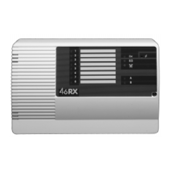
Outputs 4618 Outputs Front Panel Each member of the 46RX family uses the display panel shown in Figure 3. Figure 3. 46RX Family Display Panel The vertical column of eight LEDs indicates the status of each channel output. The symbols on the right of the panel have the following meanings:... -
Page 7: Internal Sounder
If you want to receive more than eight channels from transmitters, you can use 4619-50s as expansion units. The 4619-50 is physically similar to a 4618-50, except that it does not possess a radio receiver. Once connected, each 4619-50 behaves like an independent unit, and can be programmed separately from all the other units in the installation. -
Page 8: External Reset Connection
External Reset Connection 4618 External Reset Connection Figure 5. External Reset Connection. When the user starts the control panel exit timer the Detector Reset output removes the positive feed for six seconds. This clears the latched channels. Connecting the Sounder Figure 6. -
Page 9: Initial Start-Up
For Systems Using a 4618-60: NOTE: When installing the equipment for the first time at a new site, for a 4618-60 connect the mains power first and then the battery. At subsequent mainte- nance, or re-installations at existing sites, connect the battery first and then the supply. - Page 10 4618 You should see the Power LED glow. If the sounder is connected you should hear a short tone. For Systems Containing a 4618-50 For ALL units in the system set Mode Switch 2 (Power Mode) to OFF: 1 2 3 4 5 6 7 8 Connect the external 12V supply.
-
Page 11: Mode Switch
4618 Site Codes Site Codes You must set the 46RX family receiver and the transmitters to the same site code. The 46RX family receiver will only respond to signals from a transmitter set to the correct site code. For some modes the site code to set for the transmitters is shorter than the site code set on the 46RX family receiver. - Page 12 Allocating Transmitters to Modes 4618 Allocating Transmitters to Modes The 46RX family receivers provide a total of 22 different modes. Mode 22 is used to show the message quality of transmitters. Modes 1 to 21 provide different ways of allocating transmitter channels to receiver output channels.
- Page 13 4618 Common Output Channels Manual Reset The receiver switches a channel ON when it receives an ACTIVE signal. You must RESET the receiver to switch the channel OFF. Note that this will also switch all other channels to OFF. Toggle...
- Page 14 Modes 9 to 13, and 19 4618 1 & 2 Latching, 3-8 Momentary 1 2 3 4 5 6 7 8 1-8 Momentary 1 2 3 4 5 6 7 8 1-8 Latch ON, Manual Clear 1 2 3 4 5 6 7 8...
- Page 15 4618 Modes 14 and 15 Modes 14 And 15 - Transmitter Switch Settings At the transmitter: • Set switches 1 to 7 to the site code • Set switch 8 ON for device 1 or OFF for device 2. The receiver allocates four channels to each device. Channels 1 to 4 belong to device 1, channels 5 to 8 belong to device 2.
- Page 16 4618 Mode 20 and 21 (Group Modes) Modes 20 and 21 are used for special applications where a transmitter must activate more than one receiver. Refer to the Installation Guide supplied with the unit for detailed examples. MODE SW SETTING...
-
Page 17: Fault Finding
4618 Fault Finding Set Mode Switches 4 to 8 as follows: 1 2 3 4 5 6 7 8 Activate a transmitter Channel 1 and the jamming LED flash for the duration of the transmis- sion. The LEDs stop flashing, leaving one channel LED glowing steadily. - Page 18 4618 18 of 20 496371 Issue 1...
- Page 19 4618 Fault Finding t ’ n d i l c t i . y l t t i g i l . y l t t i t t i . l e . l e t t i t t i t t i .
- Page 20 4618 20 of 20 496371 Issue 1...
Need help?
Do you have a question about the 4618 and is the answer not in the manual?
Questions and answers