Advertisement
Table of Contents
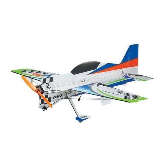
Yak54 F3P
Yak54 F3P
Instruction Manual
Introduction
Thank you for purchasing the Yak54-F3P.
The Yak54-F3P ARF has super slow flight responsiveness so you can fly high-
alpha 3D with authority. Its carbon fiber reinforced Yak54-F3P construction
provides the solid, precise feel of a balsa profile plane without the weight. This
allows you to fly the Yak54-F3P ARF outside in windier conditions that would
keep most other profile foamies grounded. The Yak54-F3P ARF is another
exciting addition to TECH ONE's outstanding line of electric RC aircraft and
accessories.
TECH ONE uses top-quality engineering and materials in everything it makes, so
you always get the maximum level of value and fun. TECH ONE backs all of its
products with the best customer service and support in the hobby so your electric
flight experience is always a positive one.
These assembly instructions are designed to guide you through the entire
assembly process of your new airplane in the least amount of time possible. Along
the way you'll learn how to properly assemble your new airplane and also learn
tips that will help you in the future. We have listed some of our recommendations
below. Please read through them before beginning assembly.
Warning
An R/C aircraft is not a toy! If misused, it can cause seriousbodily harm and
damage to property. Fly only in open areas,preferably AMA (Academy of
Model Aeronautics) approvedflying sites, following all instructions included
with your radio.Always assume the electric motor can come on at any time
souse extreme caution.Before beginning assembly of your
strongly uggest that you read through this instruction manual so you
s
canbecome familiar with the parts and the assembly sequence.Assemble the
kit according to the sequence provided in the instruction manual. Do not
attempt to modify or change the kit design as doing so could adversely
change the models flying characteristics.
Before use, please read the explanations carefully!
Yak54-F3P
, we
Specifications
Fuselage length: 815mm( 32in)
Wingspan: 786mm( 31in)
Flying Weight: 130- 150g( with battery)
Additional Required Equipment
Motor: 2404 KV: 1600
ESC: 10 A
9050 Slow Flyer Prop
Propeller:
GWS
Servo: 5G* 3
: /
Radio 4 more channel
: /
Receiver 4 more channel
Battery charger
Battery:
7.4V
350
mAh
Laser-cut 3mm genuine EPS parts for optimum strength and
Minimum weight .
Lightweight carbon fiber truss system virtually eliminates flex .
Ideal for indoor flight and capable of outdoor flight in low winds.
Minimal assembly required flight ready in as little as 3 hours .
Vibrant screen printed trim scheme.
Required Tools and Adhesives (not included in the kit)
5 Minute Epoxy
Glue
Aerosol Zip-Kicker
# 0 and #1 Phillips Head Screwdrivers
1.5mm Hex Wrench
Adjustable Wrench
Wire Cutters
Z-Bend Pliers
Needle Nose Pliers
Modeling Knife
Scissors
Electric or Hand Drill
Assorted Drill Bits
Straight Edge Ruler
Pencil
T-Pins
Builder's Triangle
220 Grit Sandpaper with Sanding Block
Masking Tape
Paper Towels
Rubbing Alcohol
Epoxy Mixing Sticks
Epoxy Mixing Cups
Soldering Iron
Advertisement
Table of Contents

Related Manuals for Techone Yak54 F3P


Summary of Contents for Techone Yak54 F3P
- Page 1 Before use, please read the explanations carefully! Yak54 F3P Yak54 F3P Instruction Manual Specifications Fuselage length: 815mm( 32in) Wingspan: 786mm( 31in) Flying Weight: 130- 150g( with battery) Additional Required Equipment Motor: 2404 KV: 1600 ESC: 10 A 9050 Slow Flyer Prop Propeller:...
-
Page 2: Kit Contents
Kit Contents A Wing with Aileron B Fuselage Side Board C Fuselage Main Board D Wing Fences E Foam Doublers (long) F Foam Doublers (short) G Wheel Covers H Control Horn Backplates I Control Horns J Round Doublers K Threads L Landing Gear Deco Foam Strips M Motor Fixed Foam N Carbon Fiber Rods... - Page 3 C/ A Glue the fuselage side board onto the fuselage main board. Install the round doublers onto the pre-reserved holes on the bottom fuselage to strengthen the joint of carbon fiber rod and foam. Bracing 2. Install the round doublers on other places. Install the doubler for the landing gear.
-
Page 4: Landing Gear
3. Landing Gear Assemble the landing gears and fix them fix them with some foam-friendly C/A. with some foam-friendly C/A. 4. Fuselage C/ A s- fuselage side board Fix the rudder with 3M magic tape. m- fuselage main board Install the motor mount and fix as shown in the picture. Install the wing fences and fix as shown in the picture. - Page 5 5. Servo and Servo Arm Fix the servo arm with some C/A aileron servo Install aileron servo and fix with some C/A. elevator servo Install elevator servo and fix with some C/A. rudder servo Install rudder servo and fix with some C/A. -...
- Page 6 6. Control Horns and Servos Aileron carbon fiber push rods. Glue together the contron horns and their backplates. Fix the aileron control horns with some C/A. Install the push rods to connect the aileron servo and control horns. Fix the rudder control horns with some C/A. Fix the elevator control horns with some C/A.
-
Page 7: Control System
Control System 7. Install the motor. Fix the wheel covers with some foam-friendly C/A. Lipo battery Use one piece of velcro to fix your receiver on the fuselage, Mount your ESC to the fuselage, using one piece of velcro. and also install your battery to the designated place on the fuselage. -
Page 8: Balance Point
Balance Point . The Center of Gravity (C/G or Balance Point) is 2 95" (75mm) from the leading edge of the wing, measured at the center of the wing. WARNING For test flying and general sport flying, we suggest you balance the airplane at the C/G recommended above.
Need help?
Do you have a question about the Yak54 F3P and is the answer not in the manual?
Questions and answers