Table of Contents
Advertisement
Advertisement
Table of Contents

Subscribe to Our Youtube Channel
Related Manuals for Di-LOG DL9206


Summary of Contents for Di-LOG DL9206
- Page 1 AUTORANGING DL9206 MULTIMETER 61010-1 CAT III 600V...
-
Page 2: Safety Information
Safety Information This manual contains information that must be followed for operating the meter safely and maintaining the meter in a safe operating condition. If this meter is not used in the manner specifi ed, the protection provided may be impaired. Warning! Warns of potential danger, refer to the instruction manual to avoid personal injury or damage to the meter. - Page 3 Where applicable use GS38 approved leads (not supplied) these are available from Di-Log. When using test leads keep fi ngers behind the fi nger guards. Do not apply more than the rated voltage, as marked on the meter between the terminals or between any terminal and ground.
- Page 4 Safety Information Before making a measurement ensure that the rotary switch is set to the appropriate range. Do not turn the rotary switch whilst making a measurement. Use the appropriate terminals, function and range for your measurements. If the value to be measured is not known use the maximum measurement position and reduce the range step by step until a satisfactory reading is obtained.
- Page 5 Safety Information Replace the battery as soon as the low battery indicator appears. If the battery is low the meter may give false readings. Turn the meter power off when not in use,. Remove the battery if the meter is in use for a long period. Constantly check the battery as it may have leaked.
-
Page 6: Input Limits
Input Limits Never apply voltage or current to the meter that exceeds the specifi ed maximum: Function Maximum V DC or V AC 1000V DC, 750V AC A DC/AC 10A DC/AC (30 seconds max every 15 minutes) Frequency, Resistance, 250V DC/AC Capacitance, Duty Cycle, Diode test, Continuity Temperature... -
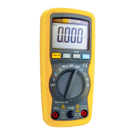
Page 7: Controls And Inputs
Controls and Inputs 6000 count Liquid Crystal Display with symbolic signs. 2. Function rotary switch. 3. 10A (positive) input terminal for 10A DC or AC measurements. 4. COM (negative) input terminal. 5. Positive input terminal. 6. HOLD pushbutton. 7. Max/Min pushbutton. 8. -
Page 8: Specifications
Specifi cations The instrument complies with: EN61010-1. Insulation: Class2, Double insulation. Overvoltage category: CATIII 600V. Display: 6000 counts LCD display with function indication. Polarity: Automatic, (-) negative polarity indication. Overrange: “OL” mark indication. Low battery indication: The “BAT” is displayed when the battery voltage drops below the operating level. - Page 9 Specifi cations DC Voltage Range Resolution Accuracy 600.0mV 0.1mV ±0.5% of rdg + 2 dgts 6.000V 60.00V 10mV ±1.2% of rdg + 2 dgts 600.0V 100mV 1000V ±1.5% of rdg + 2 dgts Input Impedance: 7.8MΩ. Maximum Input: 1000V dc or 750V ac rms. AC Voltage Range Resolution...
- Page 10 Specifi cations Resistance (Auto-ranging) Range Resolution Accuracy 600.0Ω 0.1Ω ±1.2% of rdg + 4 dgts 6.000kΩ 1Ω ±1.0% of rdg + 2 dgts 60.00kΩ 10Ω ±1.2% of rdg + 2 dgts 600.0kΩ 100Ω 6.000MΩ 1kΩ 60.00MΩ 10kΩ ±2.0% of rdg + 3 dgts Input Protection: 250V dc or 250V ac rms.
-
Page 11: Duty Cycle
Specifi cations Duty Cycle Range Resolution Accuracy 0.1%~99.9% 0.1% ±1.2% of rdg + 2 dgts Pulse width: >100us, <100ms; Frequency width: 5Hz – 150kHz Sensitivity: >0.5V RMS Overload protection: 250V dc or ac rms. Temperature Range Resolution Accuracy -20˚C~+760˚C 1˚C ±3% of rdg -4˚F~+1400˚F 1˚F... -
Page 12: Operation
Operation Warning: RISK OF ELECTROCUTION. HIGH-VOLTAGE CIRCUITS, BOTH AC AND DC, ARE VERY DANGEROUS AND SHOULD BE MEASURED WITH GREAT CARE. 1. ALWAYS turn the function switch to the OFF position when the meter is not in use. This meter has Auto OFF that automatically shuts the meter OFF if 15 minutes elapse between uses. - Page 13 Operation Range Button When the meter is fi rst turned on, it automatically goes into AutoRanging. This automatically selects the best range for the measurements being made and is generally the best mode for most measurements. For measurement situations requiring that a range be manually selected, perform the following: 1.
- Page 14 Operation Hz/duty 1. Switch to Hz/Duty range. 2. Press the Hz/Duty button to show the reading in the display and the “Hz/Duty” indicator will appear on the display.
-
Page 15: Dc Voltage Measurements
DC Voltage Measurements Caution: DO NOT MEASURE DC VOLTAGES IF A MOTOR ON THE CIRCUIT IS BEING SWITCHED ON OR OFF. LARGE VOLTAGE SURGES MAY OCCUR THAT CAN DAMAGE THE METER. 1. Set the function switch to the V DC position . 2. -
Page 16: Ac Voltage Measurements
AC Voltage Measurements Warning: RISK OF ELECTROCUTION. THE PROBE TIPS MAY NOT BE LONG ENOUGH TO CONTACT THE LIVE PARTS IN- SIDE SOME 240V OUTLETS FOR APPLIANCES BECAUSE THE CONTACTS ARE RECESSED DEEP IN THE OUTLETS. AS A RESULT, THE READING MAY SHOW 0 VOLTS WHEN THE OUTLET ACTUALLY HAS VOLTAGE ON IT. -
Page 17: Dc Current Measurements
DC Current Measurements Caution: DO NOT MAKE CURRENT MEASUREMENTS ON THE 10A SCALE FOR LONGER THAN 30 SECONDS. EXCEEDING 30 SECONDS MAY CAUSE DAMAGE TO THE METER AND/OR THE TEST LEADS. 1. Insert the black test lead banana plug into the negative (COM) terminal. -
Page 18: Ac Current Measurements
AC Current Measurements Warning: TO AVOID ELECTRIC SHOCK, DO NOT MEASURE AC CURRENT ON ANY CIRCUIT WHOSE VOLTAGE EXCEEDS 250V AC. Caution: DO NOT MAKE CURRENT MEASUREMENTS ON THE 10A SCALE FOR LONGER THAN 30 SECONDS. EXCEEDING 30 SECONDS MAY CAUSE DAMAGE TO THE METER AND/OR THE TEST LEADS. -
Page 19: Resistance Measurements
Resistance Measurements Warning: TO AVOID ELECTRIC SHOCK, DISCONNECT POWER TO THE UNIT UNDER TEST AND DISCHARGE ALL CAPACITORS BEFORE TAKING ANY RESISTANCE MEASUREMENTS. REMOVE THE BATTERIES AND UNPLUG THE LINE CORDS. 1. Set the function switch to the Ω position. 2. -
Page 20: Continuity Check
Continuity Check Warning: TO AVOID ELECTRIC SHOCK, NEVER MEASURE CONTINUITY ON CIRCUITS OR WIRES THAT HAVE VOLTAGE ON THEM. 1. Set the function switch to the position. 2. Insert the black lead banana plug into the negative (-) terminal (COM) and the red test lead banana plug into the positive (+) terminal (Ω). -
Page 21: Diode Test
Diode Test Warning: TO AVOID ELECTRIC SHOCK, DO NOT TEST ANY DIODE THAT HAS VOLTAGE ON IT. 1. Set the function switch to position. 2. Press the button until the symbol appears in the display. 3. Insert the black test lead banana plug into the negative (-) terminal (COM) and the red test lead banana plug into the positive (+) terminal(Ω). -
Page 22: Frequency Measurements
Frequency Measurements 1. Set the function switch to the FREQ position. 2. Insert the black test lead banana plug into the negative (-) terminal (COM) and the red test lead banana plug into the positive (+) terminal (F). 3. Connect the test probe tips to the circuit under test. 4. -
Page 23: Capacitance Measurements
Capacitance Measurements Warning: TO AVOID ELECTRIC SHOCK, DISCONNECT POWER TO THE UNIT UNDER TEST AND DISCHARGE ALL CAPACITORS BEFORE TAKING ANY CAPACITANCE MEASUREMENTS. REMOVE THE BATTERIES AND UNPLUG THE LINE CORDS. 1. Set the function switch to the CAP position. (“nF” and a small value will appear in the display). -
Page 24: Temperature Measurement
Temperature Measurement Warning: TO AVOID ELECTRIC SHOCK, DISCONNECT BOTH TEST PROBES FROM ANY SOURCE OF VOLTAGE BEFORE MAKING A TEMPERATURE MEASUREMENT. 1. If you wish to measure temperature in ˚F, set the function switch to the ˚F range. If you wish to measure temperature in ˚C, set the function switch to the ˚C range. -
Page 25: Replacing The Battery
Replacing the Battery Warning: TO AVOID ELECTRIC SHOCK, DISCONNECT THE TEST LEADS FROM ANY SOURCE OF VOLTAGE BEFORE REMOVING THE BATTERY COVER. 1. When the batteries become exhausted or drop below the operating voltage, “BAT” will appear in the right-hand side of the LCD display. The battery should be replaced. -
Page 26: Replacing The Fuses
Replacing the Fuses Warning: TO AVOID ELECTRIC SHOCK, DISCONNECT THE TEST LEADS FROM ANY SOURCE OF VOLTAGE BEFORE REMOVING THE FUSE COVER. 1. Disconnect the test leads from the meter and any item under test. 2. Open the fuse cover by loosening the screw on the door using a Phillips head screwdriver. - Page 27 Notes...
-
Page 28: Warranty & Maintenance
Warranty & Maintenance 24 Month Warranty Di-Log instruments are subject to stringent quality controls. If in the course of normal daily use a fault occurs we will provide a 24 month warranty (only valid with invoice). Faults in manufacture and materials defect will be rectifi ed by us free of charge, provided the instrument has not been tampered with and returned to us unopened.
Need help?
Do you have a question about the DL9206 and is the answer not in the manual?
Questions and answers