Table of Contents
Advertisement
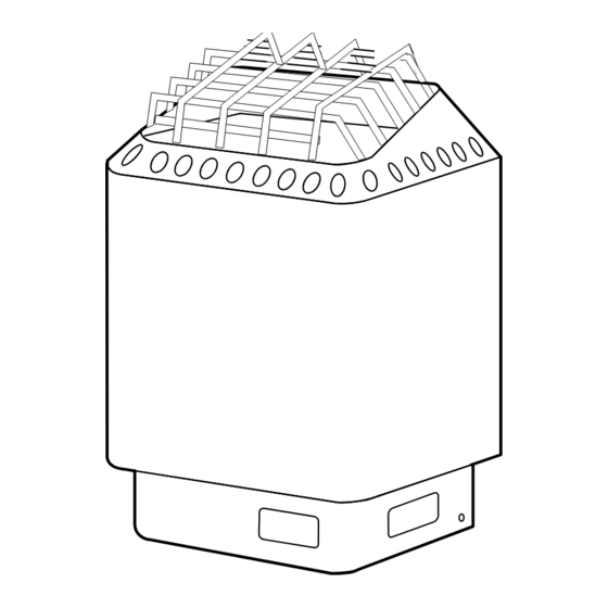
INSTALLATION AND OPERATING INSTRUCTIONS
"DIGITAL" SERIES SAUNA HEATERS
MODELS 4.5S, 6.0S, 8.0S w
(Model # 1712-45-1705,1712-60-1705,
1712-80-1705) (-3 designates 3 Phase).
Read all instructions carefully before installation. Please leave all
instructions and warranty with the owner.
WARNING
Prolonged exposure to elevated temperatures is capable of inducing
hyperthermia. Hyperthermia occurs when the internal temperature of the
body reaches several degrees above the normal body temperature of
98.6°F. The symptoms of hyperthermia include an increase in the normal
temperature of the body, dizziness, lethargy, drowsiness, and fainting. The
effects of the hyperthermia include failure to perceive heat, failure to
recognize the need to exit the room, unawareness of impending hazard,
fetal damage in pregnant women, physical inability to exit the room and
unconsciousness.
WARNING
The use of alcohol, drugs, or medication is capable of greatly increasing
the risk of fatal hyperthermia.
SECTION 1: GENERAL INFORMATION
These heaters are ETL approved by Intertek for permanent installations and
electrical connections. Built with splash proof construction, the conducting
parts are protected against water. All wiring must be performed in
accordance with national and local codes. See Diagram 2 for wire and
room size requirements. These heaters are wall mounted, 16 W x 11 D x 23
H.
4211-85-G 08-01-14
or
ith DC60 control,
WARNING
Do not take a sauna if using
alcohol, drugs or
medications.
Pregnant women or persons
with poor health should
consult their physician before
using any sauna.
Caution re hazard: Do not
use the sauna room for
drying clothes, bathing suits,
etc. Do not hang towels
above heater or place any
object other than the rocks
supplied on the heater. If any
darkening of the wall around
the heater is noticed
discontinue sauna use
immediately.
Inspect sauna regularly for
required maintenance to
heater, control and benches.
Replace wood surfaces
which show any signs of
deterioration.
The heater gets extremely hot
during operation and should
not be touched or burns may
result.
Minors should be adequately
supervised whenever near a
hot or warming sauna.
7014140 314 SKSM 113 H
Page 1
Advertisement
Table of Contents

Related Manuals for Amerec DIGITAL SERIES4.5S


Summary of Contents for Amerec DIGITAL SERIES4.5S
-
Page 1: Section 1: General Information
INSTALLATION AND OPERATING INSTRUCTIONS Page 1 WARNING Do not take a sauna if using alcohol, drugs or medications. Pregnant women or persons with poor health should consult their physician before using any sauna. Caution re hazard: Do not use the sauna room for drying clothes, bathing suits, etc. - Page 2 INSTALLATION AND OPERATING INSTRUCTIONS Page 2 DIAGRAM 1 MOUNTING BRACKET LOCATION AND MINIMUM DISTANCE TO COMBUSTIBLE MATERIAL Temperature Sensor (Upper Bench) 2" 14 3/8" B 9" Guard Rail Screws Use the long screws in the upper High Limit Control holes of the mounting bracket MINIMUM Recheck your distances from the heater to "A"...
-
Page 3: Section 4: Electrical Hook-Up
INSTALLATION AND OPERATING INSTRUCTIONS Page 3 WARNING SECTION 2: MOUNTING OF SAUNA HEATER HANGING THE HEATER Using the template provided, drill four 9/64" holes Fire sprinkler systems used to fasten the heater to the wall. Install two ¼" x 1 ½" hex head lag screws inside any sauna room should (supplied with the heater) into the upper two holes. - Page 4 INSTALLATION AND OPERATING INSTRUCTIONS Page 4 DIAGRAM 4 DIAGRAM 3 DC60 CONTROL Mounting Bracket. Control Sensor protective cover. Locate bottom Housing. of sensor 6" from ceiling and 9" left or right of heater. Note: if sensor wire is exposed on 2"...
- Page 5 INSTALLATION AND OPERATING INSTRUCTIONS Page 5 WARNING SECTION 7: DC60 CONTROL INSTALLATION & OPERATION The DC60 control uses low voltage to switch your sauna heater on and off, Do not locate benches over to adjust the room temperature, and to adjust the length of your sauna heater.
-
Page 6: Temperature Sensor
INSTALLATION AND OPERATING INSTRUCTIONS Page 6 DIAGRAM 6 WIRING DIAGRAM: HEATER MODELS DIGITAL 4.5S, 6.0S & 8.0S (Model # 1712-45-1705,1712-60-1705,1712-80-1705) (OPTIONAL) DC60 SWITCH DC60 SWITCH CIRCUIT BOARD WIRE TO K2 K4 K5 K3 TERMINAL WIRE TO BLOCK ELEMENT (Relay Layout) TEMPERATURE SENSOR 1 2 3 4 5 6... - Page 7 INSTALLATION AND OPERATING INSTRUCTIONS Page 7 SECTION 7: OPERATION, Continued SETTING THE TIME AND TEMPERATURE To change the time setting, press the control ON/OFF button to turn on the heater. Press and hold the TIME button on the control: the control will display the bath time setting. Continue to hold the TIME button pressed and the display will show the time setting changing in 5 minute increments.
- Page 8 INSTALLATION AND OPERATING INSTRUCTIONS Page 8 DIAGRAM 7 DIAGRAM 8 TYPICAL PRE-CUT WALL CONSTRUCTION HEATER SCREEN (GUARD RAIL) 1/2" wallboard 2x4" framing min 2" berglass insulation foil vapor barrier T&G soft wood Heater screen 1/2" wallboard DIAGRAM 9 DIAGRAM 10 a.
- Page 9 INSTALLATION AND OPERATING INSTRUCTIONS Page 9 WARNING SECTION 10: WARNING PLACARDS Two metal placards are included in the Installation Instruction Envelope The "CAUTION" and packaged with every Sauna Heater. The CAUTION placard must be attached "WARNING" placards must be to the interior wall of the sauna room directly above the heater where it is mounted in accordance with visible to the bather.
-
Page 10: Section 11: Ventilation
INSTALLATION AND OPERATING INSTRUCTIONS Page 10 SECTION 11: VENTILATION VENTILATION In a sauna, the air should be changed about 6 times an hour. This can be achieved by making a vent opening (fresh air inlet) in the sauna wall directly below the heater. The air outlet must be lower than the upper benches, as far as possible from the heater and about two feet higher than the fresh air inlet vent, See Diagram 9.
Need help?
Do you have a question about the DIGITAL SERIES4.5S and is the answer not in the manual?
Questions and answers