
Related Manuals for Multiaqua MHRC


Summary of Contents for Multiaqua MHRC
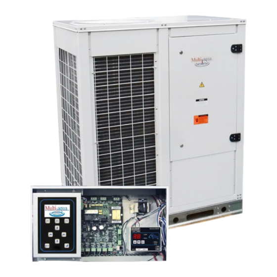
- Page 1 MHRC CHILLER CONTROL MANUAL MHRC with MCS MAGNUM Controls Rev.2015-09-25 Multiaqua, Inc. 306 Hagood Street, Easley, South Carolina 29640 • Phone: (864) 850-8990 Fax: (864) 850-8995...
-
Page 2: Revision
All Multiaqua products are designed with the future in mind. That’s why all air conditioning chiller products are fl exible, which makes it easy to adapt to virtually all kinds of building applications. -
Page 3: Table Of Contents
Table of Contents 1. Table of Contents ..............................3 2. Introduction to Multiaqua and MCS-Magnum ....................5 2.1. About the Multiaqua Heat reclaim chiller (MHRC) ..................5 2.2. About the MCS-MAGNUM ..........................5 2.3. About PC Support Software for MCS-MAGNUM ..................5 2.4. Requirements for PC Software ........................5 2.5. - Page 4 21.2.3 Alarms generated by the control algorithm ..................37 21.3. MHRC MAGNUM system alarms .......................37 21.3.1 Alarms are generated by the MHRC MAGNUM control algorithm: ...........37 21.1.1. Confi guration problem alarms ....................37 21.1.2. MCS I/O network problem alarms ..................37 21.1.3.
-
Page 5: Introduction To Multiaqua And Mcs-Magnum
The MHRC is currently available in 5 ton nominal size and scalable to 100 tons in air cooled confi guration . Variable speed and Variable capacity Digital scroll compressors allow the system to modulate its capacity to match the Heating and or Cooling requirements. -
Page 6: Mcs- Magnum Keypad - Keys And Their Functions
REVISION 1 2.5. MCS- MAGNUM KEYPAD - Keys and their functions • LCD DISPLAY - displays current condition of controller. Pressing the Menu key, displays the 10 available Menu items. • FUNCTION KEYS - F1, F2, F3 are used to Page Up and Page Down as shown below, F2 - PG(page up), F3 - PG(page down). -
Page 7: Mhrc Start Up Screens
The controller will change states to ensure the proper functioning of the MHRC package. As we review the various states, we must remember the MHRC package consists of a number of different parts: the compressors, evaporators and condensers plus the mode of operation. -
Page 8: Status Displays
PRESS F3 PG TO CONTINUE REVIEWING STATUS 4.2. UNIT COMPRESSOR LOADED HH:MM C TNK / H TNK CURRENT MHRC STATUS – UNIT IS LOADED TIME IN COOL MODE SHOWS WANTED, ACTUAL, % LOADED, DELAY AND RATE OF CHANGE PRESS F3 PG TO CONTINUE REVIEWING STATUS 4.3. -
Page 9: Compressor 1 Status- Running
REVISION 1 4.4. COMPRESSOR 1 STATUS- RUNNING HH:MM CMP 1 STATUS C TNK / H TNK COMPRESSOR IS RUNNING PROVIDES SATURATED SUCTION, SUCTION SUPERHEAT, SATURATED CONDENSING & DISCHARGE SUPERHEAT PRESS F3 PG TO CONTINUE REVIEWING STATUS 4.5. EXV VALVE OPENING HH:MM EXV 1 STATUS C TNK / H TNK... -
Page 10: Main Menu - Select Outputs Status
REVISION 1 Status Outputs 5.1. MAIN MENU - SELECT OUTPUTS STATUS HH:MM MENU, SELECT OUTPUTS THIS WILL ALLOW THE USER TO DISPLAY DETAILS OF THE OUTPUTS STATUS BOTH ANALOG & DIGITAL PRESS (ENTER KEY) TO SELECT 5.2. UNIT RELAYS STATUS HH:MM OUTPUTS (RELAY &... -
Page 11: Status Inputs
REVISION 1 Status Inputs 6.1. PRESS MENU - SELECT INPUTS HH:MM MENU KEY, SELECT INPUTS PRESS ENTER THIS WILL ALLOW USER TO DISPLAY DETAILS OF THE INPUTS BOTH ANALOG & DIGITAL 6.2. INPUTS (SENSOR STATUS) HH:MM INPUTS (ANALOG & DIGITAL) THE FIRST FOUR INPUTS ARE PRESENTED ... -
Page 12: Press Menu - Select Alarms
REVISION 1 Alarms 7.1. PRESS MENU - SELECT ALARMS HH:MM MENU KEY, SELECT ALARMS ENTER THIS WILL ALLOW USER TO DISPLAY DETAILS OF THE ALARMS THERE ARE A MAXIMUM OF 100 ALARMS PRESENTED TWO TO A SCREEN WITH MOST CURRENT FIRST 7.2. -
Page 13: Graphs
REVISION 1 Graphs 8.1. PRESS MENU - SELECT GRAPHS HH:MM MENU KEY, SELECT GRAPHS, PRESS ( ) ENTER THIS WILL ALLOW USER TO DISPLAY DETAILS OF A GRAPH ONE ITEM IS GRAPHED AT A TIME IT WILL BE PLOTTED IN REAL TIME 8.2. -
Page 14: Press Menu - Select Set Points
REVISION 1 Set Points 9.1. PRESS MENU - SELECT SET POINTS HH:MM MENU KEY, SELECT SETPOINTS PRESS ENTER KEY THIS WILL ALLOW THE USER TO DISPLAY DETAILS OF SETPOINTS SETPOINTS CAN BE DISPLAYED BASED ON AUTHORIZATION LEVEL 9.2. DISPLAY SET POINTS HH:MM THE 1ST FOUR SETPOINTS ARE DISPLAYED ... -
Page 15: Service Tools
REVISION 1 10. Service Tools 10.1. PRESS MENU - SELECT SERV TOOLS HH:MM MENU KEY, SELECT SERV TOOLS, PRESS ( ) ENTER THIS WILL ALLOW USER TO DISPLAY DETAILS OF SERV TOOLS 10.2. SERV TOOLS OPTIONS HH:MM SERV TOOLS THE SERV TOOL OPTIONS ARE DISPLAYED ↑... -
Page 16: System Info Screen 2
REVISION 1 10.5. SYSTEM INFO SCREEN 2 HH:MM SERV TOOLS SYSTEM INFO PRESS ENTER KEY TO SELECT 10.6. SYSTEM INFO SCREEN 3 HH:MM SYSTEM INFO SHOWS FIRMWARE VERSION & CONFIG NAME PG CONTINUES TO NEXT SYSTEM INFO 10.7. SYSTEM INFO SCREEN 4 HH:MM SYSTEM INFO SHOWS COMPANY NAME... -
Page 17: Press Menu - Select Lckout Rst
REVISION 1 11. Lockout Reset Alarms 11.1. PRESS MENU - SELECT LCKOUT RST HH:MM MENU KEY, SELECT LCKOUT RST ENTER KEY THIS WILL ALLOW USED TO DISPLAY ANY LOCKOUTS 11.2. NO CURRENT LOCKOUTS HH:MM IF NO LOCKOUTS EXIST YOU WILL BE NOTIFIED IF THE UNIT IS IN LOCKOUT YOU WILL BE ALLOWED TO RESET. -
Page 18: Press Menu - Select Lckout Alarm
REVISION 1 12. Lockout Alarms 12.1. PRESS MENU - SELECT LCKOUT ALARM HH:MM MENU KEY, SELECT LCKOUT ALARMS, PRESS ( ) ENTER THIS WILL ALLOW USER TO DISPLAY ANY LOCKOUTS ALARMS 12.2. 1ST LCKOUT ALARM DISPLAYED HH:MM SYSTEM INFO LOCKOUT ALARM NO LOCKOUT ALARMS... -
Page 19: Press Menu - Select Passwords
REVISION 1 13. Passwords 13.1. PRESS MENU - SELECT PASSWORDS HH:MM MENU KEY, SELECT PASSWORD, PRESS ( ) ENTER THIS WILL ALLOW USER TO GET AUTHORIZED 13.2. ENTER PASSWORD HH:MM ENTER YOUR 4 DIGIT PASSWORD MUST BE NUMBERS BETWEEN 1 & 8 TO ENTER FROM KEYPAD CAN BE ANY COMBINATION FROM LAPTOP 13.3. -
Page 20: Main Menu
PRESS ENTER 14.2. HELP DISPLAY HH:MM DESCRIPTION OF THE SYMBOLS USED TO MOVE CURSOR & KEYS USED TO ENTER PASSWORD 14.3. MHRC LARGE TYPE DISPLAY HH:MM PRESS F3 KEY AT MAIN MENU 14.4. LARGE TYPE DISPLAY HH:MM DISPLAY SHOWS LARGE TYPE... -
Page 21: Unit In Power Up
REVISION 1 15. MHRC MODES 15.1. UNIT IN POWER UP This state is entered when the Magnum is powered up or the system has been reset. The system will remain in this state for the time specifi ed in set point #23 “POWER DELAY” or for 60 seconds if not active. In this state all Relay Outputs are turned off. -
Page 22: Unit Is Loading
REVISION 1 15.7. UNIT IS LOADING This state is entered when more capacity is required. Every second an adjustment is made to the step delay. When the delay reaches zero, the counter “steps wanted on” is increased by 1. 15.8. RUN/STOP SW OFF This state is entered when the run stop switch is off, in the stop position. -
Page 23: Mhrc Sequence Of Operation
Set Points #25 “STEP SENSIT” and Set Point #26 “STEP DELAY“. e. If the ROC is indicating a suffi cient increase in MHRC Out Temperature (ROC < Set Point #27 “MAX ROC-“) the capacity control logic stop unloading and holds the current capacity. - Page 24 REVISION 1 7. Once it has been determined that a compressor is wanted on, the MAGNUM reviews the ‘NO RUN CIRCUIT CONTROL STATES’ for an available compressor. 8. The condenser fan control logic runs once every second. Pumps and fans are cycled based on the compressor(s) discharge pressure and Set Point #45 to #55, depending on condenser type.
-
Page 25: Mcs-Magnum Exv Suctin/Discharge Superheat Logic
REVISION 1 17. MCS-MAGNUM EXV Suctin/Discharge Superheat Logic... - Page 26 REVISION 1...
- Page 27 REVISION 1...
-
Page 28: Exv Related Setpoints
REVISION 1 17.1.1. EXV Related Setpoints. (Refer Setpoints 9-20, 65-72, 109-110, 199-201, 205, 215, 217, and 230). These Setpoints were added to provide fi ne-tuning to the testing of the movement of the superheat temperature. Refer to EXV control logic chart in a previous section. 17.1.2. - Page 29 REVISION 1 18. MAGNUM Condenser Control Strategy Modulating Step Common - This type of condenser has a common fan bank for the system. The control will be on the systems highest discharge pressure. The Relay Outputs are also supported along with an Analog Output When the system is in both heating and cooling the condenser fan is not used.
- Page 30 REVISION 1 19. MCS-CONNECT Display...
-
Page 31: Mhrc Magnum Setpoints
REVISION 1 20. MHRC MAGNUM Setpoints Name Description Cold Tank Targ Cold Tank Target. This value is used as the base to develop the Control Zone. The control target is used with the control zone and rate of change of the controlling sensor to determine required action for the Magnum. - Page 32 REVISION 1 Name Description MAX ROC - If the negative Rate of Change exceeds this value we are approaching the target fast enough. The capacity control state is set to HOLDING. Used only with the Magnum Control Zone control method. MAX ROC + If the positive Rate of Change exceeds this value we are approaching the target fast enough.
- Page 33 REVISION 1 Name Description ACYC ON->ON This is the anti-cycle time delay (in seconds) from when the compressor was turned on. This value is used in a calculation to determine how long a compressor should be in the anti-cycle state. Defi nes the number of cycles per hour the compressor can have.
- Page 34 REVISION 1 Name Description UNSAFE SUCT If active, the Magnum checks for unsafely low suction pressure for each running compressor. If suction pressure is less than this value for the specifi ed period of time a lockout occurs. NOTE: The time period specifi...
- Page 35 REVISION 1 Name Description FREEZE If active, the Magnum will compare the leaving temperature to this Setpoint. If it is less than this value for the specifi ed period of time, a safety trip occurs. UNLOADED OFF If active, the system is fully unloaded and the control temperature is greater than this value, then the capacity state will be set to holding.
-
Page 36: Mhrc Magnum Alarms And Safeties
REVISION 1 21. MHRC MAGNUM Alarms and Safeties 21.1. Introduction There are three types of alarms that are generated by the MHRC MAGNUM control logic: ■ Information only alarms, ■ MHRC MAGNUM system alarms and ■ MHRC MAGNUM setpoint safety alarms. -
Page 37: Alarms Generated By The Control Algorithm
INVALID CFG VER (version number of the confi gurator is invalid) INVALID CFG TYPE (the type does not agree with software, MHRC software with a home unit confi guration) 21.1.2. MCS I/O network problem alarms These alarms indicate problems with the MCS I/O network, the system can be accessed but the system is in a lock out state, LOST I/O. -
Page 38: Mhrc Unit Safeties
If the calculated air fl ow % value falls below the value in setpoint #41 “LOW AIR FLOW” and it remains there for the time specifi ed in the safety time of that setpoint, the MHRC will be locked out and a “LOW AIR FLOW”... -
Page 39: Mhrc Compressor Safeties
PHASE LOSS If the digital input for the phase loss indicator is on and it remains on for two seconds, the MHRC will be locked out and a “PHASE LOSS” alarm generated. This fault requires a manual reset via the LCD/Keypad or MCS-CONNECT. -
Page 40: Condenser Fan Safeties
The following are a list of safeties that are incorporated in the MHRC control for condenser fans. These safeties are checked every second. Each condenser fan is tested individually. If a safety condition exists, action will be taken on that condenser fan only, other condenser fans will continue to function normally. -
Page 41: Heating Stages Safeties
The following are a list of safeties that are incorporated in the MHRC control for heating stages. These safeties are checked every second if the associated heating stage is on. Each heating stage is tested individually. If a safety condition exists, action will be taken on that heating stage only, other heating stages will continue to function normally. - Page 42 REVISION 1 22. APPENDIX A - MAGNUM No Run Capacity Run States There are a number of functions that will not allow the MHRC to run, as follows: (These may be viewed by pressing selecting ‘Status” from the Menu key.) 1.
-
Page 43: Appendix B - Details Of Magnum
REVISION 1 23. APPENDIX B - Details of MAGNUM MCS-MAGNUM (Rev 8.1+) Input PWR +12 VDC RS485 MCSI/O Ethernet Fuse PWR Input Terminal Spare Input Power Fuse Twelve (12) Sensor Input Ten (10) Relay Terminals Output terminals. (Analog or (COMMON, Digital) NO,NC) Four (4) Digital... -
Page 44: Appendix C - Mcs Sensors - Quick Reference Sheet
REVISION 1 24. APPENDIX C - MCS SENSORS - Quick Reference Sheet 24.1. MCS-CT 300 Current Transformer 24.2. MCS-667 Pressure Transducer... -
Page 45: Mcs-Ds-Interface Board
REVISION 1 24.3. MCS-DS-INTERFACE BOARD 24.4. MCS-T-100 - TEMPERATURE SENSOR... - Page 46 REVISION 1 APPENDIX E - MHRC Digital Scroll Drawings...
- Page 47 REVISION 1 APPENDIX E - MHRC Digital Scroll Drawings...
- Page 48 REVISION 1 APPENDIX E - MHRC Digital Scroll Drawings...
- Page 49 REVISION 1 APPENDIX E - MHRC Digital Scroll Drawings...
- Page 50 REVISION 1 APPENDIX E - MHRC Digital Scroll Drawings...
-
Page 51: Appendix F - Confi Guration Files - Digital Scroll
REVISION 1 26. APPENDIX F - Confi guration Files - Digital Scroll System Information Company Name: MULTI AQUA Site and/or Unit Name: MHRC #1 Model Name: DIGITAL SCROLL Serial Number: 2015-07-0000001 Config Version: Config Type: MHRC Mag Technician Initials: Revision Number: Firmware Version: 17.14I... - Page 52 REVISION 1 Appendix F - MHRC CONFIGURATION - DIGITAL SCROLL MAGNUM Information Display Units Deg F \ PSI Default Display Key UNIT STATUS Total Number of RO's Total Number of AO's Total Number of SI's Total Number of RO Boards...
- Page 53 REVISION 1 Appendix F - MHRC CONFIGURATION - DIGITAL SCROLL Output and Input Information for Magnum Output Name Type Input Name Type AO Name Digital or OffSet M-1 Comp Step w\ EXV M-1 ColdTank MCST100 CMP LOAD% M-2 HotSV1A&B Standard...
- Page 54 REVISION 1 Appendix F - MHRC CONFIGURATION - DIGITAL SCROLL...
-
Page 55: General Information
REVISION 1 Appendix F - MHRC CONFIGURATION - DIGITAL SCROLL MAG V17 CHL Information General Information Number of Circuits: Total Capacity Steps: Unit Type Cooling Only 1st MOD Motor Limit: Not Used Turbo Ice Machine: Lost BMS Comm.: Unit Control... - Page 56 REVISION 1 Appendix F - MHRC CONFIGURATION - DIGITAL SCROLL Evaporator Information Capacity Control Control Method: Control Zone Control Temperature On: Leaving Temp Entering Temperature: SI M-3 HotTank Leaving Temperature: SI M-1 ColdTank Target Reset: Normal AI 0-5 Volts Target (SP #1) Reset:...
- Page 57 REVISION 1 Appendix F - MHRC CONFIGURATION - DIGITAL SCROLL Lockout Information Lockouts based on I/O boards not enabled Boiler Information Boiler Logic Not Enabled Circuit Information on Next Page ---->...
- Page 58 REVISION 1 Appendix F - MHRC CONFIGURATION - DIGITAL SCROLL...
- Page 59 REVISION 1 Appendix F - MHRC CONFIGURATION - DIGITAL SCROLL...
- Page 60 REVISION 1 Appendix F - MHRC CONFIGURATION - DIGITAL SCROLL...
- Page 61 REVISION 1 Appendix F - MHRC CONFIGURATION - DIGITAL SCROLL...
- Page 62 REVISION 1 Appendix F - MHRC CONFIGURATION - DIGITAL SCROLL Schedule Information Operating Schedule Day of the Week On Sched #1 Off Sched #1 On Sched #2 Off Sched #2 Sunday 00:00 24:00 00:00 24:00 Monday 00:00 24:00 00:00 24:00...
- Page 63 REVISION 1 Appendix F - MHRC CONFIGURATION - DIGITAL SCROLL No User Logic AO Information No User Logic RO Information User Logic SI Information SI 1-1 CMP1%=100 = AO M-1 Fixed Value 1 100 Display Type = DIGITAL/SW Comments: SI 1-2 CMP1%<100 =...
-
Page 64: Appendix G - Mhrc Frequency Drive Drawings
REVISION 1 Appendix G - MHRC Frequency Drive Drawings... - Page 65 REVISION 1 Appendix G - MHRC Frequency Drive Drawings...
- Page 66 REVISION 1 Appendix G - MHRC Frequency Drive Drawings...
- Page 67 REVISION 1 Appendix G - MHRC Frequency Drive Drawings...
- Page 68 REVISION 1 Appendix G - MHRC Frequency Drive Drawings...
-
Page 69: Appendix H - Confi Guration Files - Frequency Drive
REVISION 1 28. APPENDIX H - Confi guration Files - Frequency Drive System Information Company Name: MULTI AQUA Site and/or Unit Name: MHRC #1 Model Name: VFD SCROLL Serial Number: 2015-07-0000001 Config Version: Config Type: MHRC Mag Technician Initials: Revision Number: Firmware Version: 17.14I... - Page 70 REVISION 1 Appendix H - MHRC CONFIGURATION - FREQUENCY DRIVE MAGNUM Information Display Units Deg F \ PSI Default Display Key UNIT STATUS Total Number of RO's Total Number of AO's Total Number of SI's Total Number of RO Boards...
- Page 71 REVISION 1 Appendix H - MHRC CONFIGURATION - FREQUENCY DRIVE Output and Input Information for Magnum Output Name Type Input Name Type AO Name Digital or OffSet M-1 COMP Step w\ EXV M-1 C TANK TMP MCST100 COMP % M-2 HotSV1A&B...
- Page 72 REVISION 1 Appendix H - MHRC CONFIGURATION - FREQUENCY DRIVE...
- Page 73 REVISION 1 Appendix H - MHRC CONFIGURATION - FREQUENCY DRIVE MAG V17 CHL Information General Information Number of Circuits: Total Capacity Steps: Unit Type Cooling Only 1st MOD Motor Limit: Not Used Turbo Ice Machine: Lost BMS Comm.: Unit Control...
- Page 74 REVISION 1 Appendix H - MHRC CONFIGURATION - FREQUENCY DRIVE Evaporator Information Capacity Control Control Method: Control Zone Control Temperature On: Leaving Temp Entering Temperature: SI M-3 H TANK TMP Leaving Temperature: SI M-1 C TANK TMP Target Reset: Normal AI 0-5 Volts...
- Page 75 REVISION 1 Appendix H - MHRC CONFIGURATION - FREQUENCY DRIVE Lockout Information Lockouts based on I/O boards not enabled Boiler Information Boiler Logic Not Enabled Circuit Information on Next Page ---->...
- Page 76 REVISION 1 Appendix H - MHRC CONFIGURATION - FREQUENCY DRIVE...
- Page 77 REVISION 1 Appendix H - MHRC CONFIGURATION - FREQUENCY DRIVE...
- Page 78 REVISION 1 Appendix H - MHRC CONFIGURATION - FREQUENCY DRIVE...
- Page 79 REVISION 1 Appendix H - MHRC CONFIGURATION - FREQUENCY DRIVE...
- Page 80 REVISION 1 Appendix H - MHRC CONFIGURATION - FREQUENCY DRIVE Schedule Information Operating Schedule Day of the Week On Sched #1 Off Sched #1 On Sched #2 Off Sched #2 Sunday 00:00 24:00 00:00 24:00 Monday 00:00 24:00 00:00 24:00...
- Page 81 REVISION 1 Appendix H - MHRC CONFIGURATION - FREQUENCY DRIVE BMS Points Compressor State Chart State # State # BACnet State Text/Name MCS & Modbus LOST IO LOCKED CMP LOCKED OUT SWITCHED OFF UNLD & PMPDWN CMP ANTICYCLE CMP OFF/READY...
- Page 82 REVISION 1 Appendix H - MHRC CONFIGURATION - FREQUENCY DRIVE No Lookup Table SI Information S:\! Customer Jobs\Multiaqua\VFD unit\MHRC VFD 9-15-15-B.cfg CONFIG DATE = 9/15/15 at 04:09 PM PRINT DATE = 9/24/15 02:36 PM No Lookup Table AO Information S:\! Customer Jobs\Multiaqua\VFD unit\MHRC VFD 9-15-15-B.cfg...
- Page 83 REVISION 1 Appendix H - MHRC CONFIGURATION - FREQUENCY DRIVE Lookup Table Detail Information for Magnum Lookup Table Setup # Number Of Input Column Output Column Input Column Output Column Minimum Auth Rows Name Name Display Type Display Type Level...
-
Page 84: Appendix I - Mcs Trouble Shooting Reference
REVISION 1 29. APPENDIX I - MCS Trouble Shooting Reference (A more detailed troubleshooting guide is available on our website: www.MCScontrols.com) PROBLEM POTENTIAL SOLUTION No Sensor + 5 vdc or sensor +5 vdc Indicates a possible shorted input sensor output is less than 4.90 vdc. Remove all sensor terminal blocks. - Page 85 REVISION 1 PROBLEM POTENTIAL SOLUTION SI from AMPS board 10 A low. This indicates a problem with this SI only. Jumper setting on this SI in wrong position. Incorrect sensor type used. INVALID CONFIG VER Indicates layout of CFG wrong. CFG layout for different version than software INVALID CONFIG TYPE Indicates CFG incompatible with software.
- Page 86 Multiaqua, Inc. 306 Hagood Street, Easley, South Carolina 29640 Phone: (864) 850-8990 Fax: (864) 850-8995...
Need help?
Do you have a question about the MHRC and is the answer not in the manual?
Questions and answers