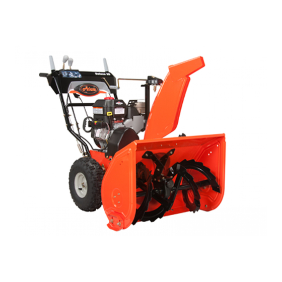
Ariens 921017 - Deluxe 24 Platinum Owner's/Operator's Manual
921 series sno-thro
Hide thumbs
Also See for 921017 - Deluxe 24 Platinum:
- Parts manual (33 pages) ,
- Owner's manual (42 pages)
Table of Contents
Advertisement
Owner/Operator Manual
Manuel Du Propriétaire/Utilisateur
E10
921 Series
Sno-Thro
The use of any gasoline exceeding 10% ethanol (E10) or
10% MTBE will void the product warranty.
L'utilisation d'une essence contenant plus de 10% d'éthanol
(E10) ou de 10% de MTBE annulent la garantie.
ENGLISH
FRANÇAIS
®
Models
921013 – Deluxe 30
(SN 075000 +)
921017 – Deluxe 24 Platinum
(SN 075000 +)
921018 – Deluxe 30 Platinum
(SN 075000 +)
921022 – Deluxe 28
(SN 075000 +)
921023 – Deluxe 28 Track
(SN 075000 +)
921027 – Deluxe 28
(SN 000101 +)
921031 – Deluxe 24
(SN 075000 +)
921034 – Deluxe 28
(SN 075000 +)
04335900J 11/12
Printed in USA
Advertisement
Table of Contents

Related Manuals for Ariens 921017 - Deluxe 24 Platinum


Summary of Contents for Ariens 921017 - Deluxe 24 Platinum
- Page 1 921 Series Sno-Thro ® Owner/Operator Manual Manuel Du Propriétaire/Utilisateur Models 921013 – Deluxe 30 (SN 075000 +) 921017 – Deluxe 24 Platinum (SN 075000 +) 921018 – Deluxe 30 Platinum (SN 075000 +) 921022 – Deluxe 28 (SN 075000 +) 921023 –...
-
Page 2: Table Of Contents
PRODUCT REGISTRATION package. They are printed on a serial number The Ariens dealer must register the product label, located on the frame of your unit. at the time of purchase. Registering the product will help the company process warranty claims or contact you with the latest service information. -
Page 3: Unauthorized Replacement Parts
The selling dealer is responsible for explaining the terms and limitations of the warranty coverage offered in the country of sale. 6. Fill out a Product Registration Card and return the card to the Ariens Company or go to www.ariens.com. EN - 3... -
Page 4: Safety
SAFETY NOTATIONS WARNING: To avoid injury to NOTE: General reference information for hands and feet, always disengage proper operation and maintenance practices. clutches, shut off engine, and wait IMPORTANT: Specific procedures or for all movement to stop before information required to prevent damage to unclogging or working on snow unit or attachment. - Page 5 1. DANGER! 2. DANGER! Danger! Danger! ONLY use clean-out tool to clear blockages. NEVER use your hands. ROTATING PARTS! ONLY use clean-out tool to clear blockages. NEVER use your hands. High speed Never direct discharge impeller rotates below towards persons or discharge opening.
-
Page 6: Emission Control System
NEVER place your hands or any part of your components can only be adjusted by an body or clothing inside or near any moving part Ariens Company dealer or an authorized while unit is running. engine manufacturer's service center. ALWAYS keep hands away from all pinch Contact your Ariens Company Equipment points. - Page 7 Abnormal Vibrations are a warning of trouble. Never fill containers inside a vehicle or on a Striking a foreign object can damage unit. truck or trailer bed with a plastic liner. Always Immediately stop unit and engine. Remove key place containers on the ground away from your and wait for all moving parts to stop.
-
Page 8: Assembly
.38-16 (921013, 018) over boxed unit could result in If any of the contents listed are missing personal injury or damage to unit. contact your local Ariens dealer. Use only Ariens approved parts; unapproved parts PACKAGE CONTENTS may void the unit warranty. - Page 9 ASSEMBLY Tools Required: • Pliers • Open-End Wrenches: 3/8, 7/16, 1/2, 9/16" and/or Adjustable Wrench • Tire Gauge • Torque Wrench (Optional) • Phillips Screwdriver Unfold Lower Handlebar (Figure 4) IMPORTANT: Be sure to block wheels or secure unit so it does not move during assembly.
- Page 10 Unfold Upper Handlebar Assembly (Figure 7 and 8) 1. Rotate the handlebar into operating position. NOTE: Be careful not to damage cable spring hooks when rotating handlebar upward. 1. Wire Harness 2. Cable Tie 3. Cable Anchor 4. Engine Electrical Plug Figure 8 3.
- Page 11 Install Discharge Chute and 921013, 022, 023, 027, 031, 034 Discharge Chute Crank (921013, 022, 023, 027, 031, 034) (Figure 10 and 11) 1. Grease underside of discharge chute ring (if not already greased). 2. Remove mounting hardware from auger housing (Figure 10).
- Page 12 OS7040 1. Chute Rod 2. Gear Cover 3. Control Assembly 4. Gear Assembly 5. Chute Control Cable 6. Alignment Marker 7. Chute Pedestal 8. Rubber Grommet 9. Hair Pin Figure 13 1. Mounting Holes NOTE: To ensure the discharge chute follows 2.
-
Page 13: Check Tire Pressure
Remote Deflector Control (Figure 14) NOTE: Connect the barrel cable end to the chute deflector cable anchor before clipping the cable to the discharge chute cable bracket. 1. Route deflector cable along the left side of the chute pedestal. 2. Insert the barrel cable end into the bracket on left side of chute deflector (Figure 14). - Page 14 Check Track Tension Check Function of all Controls (921023) Ensure unit runs and performs properly. Refer to OPERATION on page 17. Check tracking of unit and tension the tracks as required (see Track Tension Adjustment Run-in Attachment Belt on page 34). 1.
-
Page 15: Controls And Features
CONTROLS AND FEATURES 921017, 018 Figure 16 1. Skid Shoe 2. Clean-Out Tool 3. Remote Discharge Chute Deflector 4. Belt Cover 5. Headlight 6. Discharge Chute 7. Impeller 8. Chute Crank 9. Quick Turn Chute Control (921017, 018) EN - 15... - Page 16 Figure 17 1. Attachment Clutch Lever 11. Recoil Starter Handle 2. Speed Selector 12. Throttle 3. Traction Drive Clutch Lever 13. Choke Control Knob 4. Remote Deflector Control 14. Ignition Key 5. Height Adjuster Trigger (921023) 15. Fuel Tank and Cap 6.
-
Page 17: Operation
OPERATION IMPORTANT: If the belt squeals continuously when the attachment clutch lever is engaged, WARNING: AVOID INJURY. Read the impeller may be frozen in the auger and understand the entire Safety housing. Immediately release the attachment section before proceeding. clutch lever and move the unit into a heated area to thaw. - Page 18 Choke Control Knob To clear the discharge chute: 1. Shut off the engine. 1.Choke Closed position: chokes off air 2. Wait 10 seconds and make sure impeller to engine for easier blades have stopped rotating. start. 3. Remove the snow clean-out tool (1) from 2.Choke Open the auger housing and use it to remove position: allows for...
- Page 19 Wheel Unlocked Axle Lock OS7105 Figure 20 IMPORTANT: DO NOT force frozen chute controls. If frozen, take to warm place until controls are free. Axle Lock Pin (921031) (Figure 21) Use the axle lock pin to lock or unlock the right or left wheel.
-
Page 20: Scraper Blade
Remote Wheel Lock Normal (921013, 022, 027, 034) Squeeze and release the remote wheel lock control to lock the left wheel for better traction when throwing snow or to unlock the left wheel for easier steering. NOTE: The wheel lock will not release when under load. - Page 21 PRE-START IMPORTANT: Excessively oxygenated or reformulated fuels (fuels blended with 1. Frozen Impeller alcohols or ethers) can damage the fuel system or cause performance problems. If IMPORTANT: Before starting engine, check any undesirable operating problems occur, impeller to be sure it is not frozen. use a gasoline with a lower percentage of To check impeller: alcohol or ether.
-
Page 22: Starting And Shut Off
7. Check Engine Fuel & 10. Set throttle to Part Throttle or Slow position for adaptation to outside Crankcase Oil temperature or travel. Set throttle to Fast position for normal operation. WARNING: AVOID INJURY. Read Electric Start (120V) and understand the entire Safety section before proceeding. -
Page 23: Maintenance
ALWAYS direct snow away from area to be cleared and with direction of the wind. MAINTENANCE Ariens Dealers will provide any service or IMPORTANT: Ensure unit is secure and will adjustments which may be required to keep not tip over. Strap and clamp onto bench if your unit operating at peak efficiency. -
Page 24: Maintenance Schedule
MAINTENANCE SCHEDULE CHECK CLUTCH OPERATION The chart below shows the recommended Auger / impeller must stop within 5 seconds maintenance schedule that should be when attachment clutch lever is released. performed on a regular basis. More frequent Wheels must stop quickly when traction drive service may be required. -
Page 25: General Lubrication
2. Oil Fill Plug NOTE: Inspect seal washer for wear or 3. Seal Washer rubber deterioration and replace as needed. IMPORTANT: Use only Ariens L3 synthetic Figure 24 OS7132 severe duty gear lube (Part Number 00068800). Use of other lubricants will void GENERAL LUBRICATION unit warranty. -
Page 26: Service And Adjustments
Grease Figure 25 SERVICE AND ADJUSTMENTS SKID SHOES WARNING: AVOID INJURY. Read (Figure 26) and understand the entire Safety IMPORTANT: Skid shoes should be adjusted section before proceeding. as conditions require. Allow 1/8 in. (3 mm) between scraper blade and hard smooth SCRAPER BLADE surfaces. - Page 27 SHEAR BOLTS engage the mechanism. (Figure 27) 4. Tighten the bottom jam nut. IMPORTANT: Use only Ariens OEM shear 5. Check function of remote wheel lock. If bolts for replacement. Use of any other type wheel lock does not function properly,...
-
Page 28: Deluxe
1. Forward Adjustment Nut 2. Rear Adjustment Nut Figure 30 If chute does not rotate freely: Tighten the cable by loosening the forward adjustment nut, and then tightening the rear adjustment nut against the bracket until all cable slack is removed and lock arm engages teeth (Figure 30). - Page 29 Remove Attachment Cable Slack 5. Secure adjustment pivot pin with hairpin. 6. Make sure the speed selector shifts into 1. Shut off engine, remove key, disconnect each speed position. spark plug wire and allow unit to cool 7. Check forward and reverse speeds: completely.
-
Page 30: Deluxe
Check Attachment Idler Arm Roller Check Attachment Brake Clearance (Figure 36) 1. With the attachment clutch lever (Figure 35) disengaged, brake pad must contact 1. Place the unit into the service position. attachment belts. With clutch lever Remove the bottom cover. engaged, brake pad must be more than 2. - Page 31 ATTACHMENT DRIVE BELT REPLACEMENT Remove old attachment drive belts: 1. Shut off engine, remove key, disconnect spark plug wire and allow unit to cool completely. 2. Loosen hardware securing belt cover to unit. NOTE: DO NOT completely remove the hardware from unit. 3.
-
Page 32: Traction Drive Belt Replacement
921013, 022, 023, 027, 031, 034 921017, 018 1. Traction Drive Belt 2. Engine Sheave 3. Attachment Drive Belts 4. Belt Finger 5. Attachment Belt Idler 6. Attachment Idler Adjustment Nut 7. Traction Belt Idler Figure 39 1. Belt Cover 5. -
Page 33: Friction Disc Replacement
FRICTION DISC REPLACEMENT 4. Pull idler away from traction drive belt and remove belt from idler pulley, engine 1. Shut off engine, remove key, disconnect sheave and driven pulley (it may be spark plug wire and allow unit to cool necessary to turn engine pulley using completely. - Page 34 To adjust (Figure 43): 1. Tighten the adjuster nut to tighten the track tension. Loosen the adjuster nut to reduce track tension. 2. Check that unit tracks straight with no pulling to either side. Track Adjusters OS7228 Figure 43 HEIGHT ADJUSTER CABLE 1.
-
Page 35: Storage
(see ACCESSORIES MAINTENANCE on page 23). Touch up all scratched painted surfaces. See your authorized Ariens dealer to add the additional accessories available to your Remove weight from wheels by putting Sno-Thro. blocks under frame or axle. -
Page 36: Troubleshooting
TROUBLESHOOTING PROBLEM PROBABLE CAUSE CORRECTION Engine will not 1. Fuel tank is empty. 1. Fill fuel tank (see FILLING FUEL TANK on page 20). crank/start. 2. Fuel shut-off valve closed. 2. Open fuel shut-off valve. 3. Build up of dirt and residue 3. -
Page 37: Specifications
SPECIFICATIONS 921017 921018 921013 Model Number Deluxe 24 Deluxe 30 Description Deluxe 30 Platinum Platinum Engine Briggs & Stratton Briggs & Stratton Briggs & Stratton Engine Polar Force 1150 Polar Force 1450 Polar Force 1650 14.5 (19.66) 11.5 (15.59) 16.5 (22.37) Gross Torque* –... - Page 38 SPECIFICATIONS Model Number 921022 921023 921027 921031 921034 Description Deluxe 28 Deluxe 28 Track Deluxe 28 Deluxe 24 Deluxe 28 Engine Engine Model Briggs & Stratton Polar Force 1150 Briggs & Stratton Polar Force 1450 Gross Torque* – lbf-ft (N•m) 11.5 (15.59) *Engine output stated in gross torque per SAE J1940 as rated by engine manufacturer Displacement –...
-
Page 39: Warranty
® ® Sno-Thro , Sno-Tek Chore Performing Equipment Limited Warranty Ariens Company (Ariens) warrants to the original purchaser that Ariens, Gravely, Parker, and Countax ® ® brand chore performing equipment (including Sno-Thro and Sno-Tek equipment) purchased on or after 1/1/2012 will be free from defects in material and workmanship for the time period noted in the chart below. -
Page 40: Customer Responsibilities
Register the product immediately at the time of sale. If the dealer does not register the product, the customer must complete the product registration card in the literature package and return it to the Ariens Company, or register the unit online at www.ariens.com, www.gravely.com, www.countax.com, www.parkersweeper.com. - Page 41 Exclusions – Items Not Covered by This Warranty • Parts that are not genuine Ariens, Gravely, Parker or Countax service parts are not covered by this warranty and may void the warranty. • Damages resulting from the installation or use of any part, accessory, or attachment which is not approved by the Ariens Company for use with product(s) identified herein are not covered by this warranty.
- Page 42 EVAPORATIVE EMISSION CONTROL WARRANTY STATEMENT YOUR WARRANTY RIGHTS AND OBLIGATIONS (3.) Any warranted part that is scheduled for replacement The CARB (California Air Resources Board), the EPA, and Ariens as required maintenance in the written instructions Company are pleased to explain the evaporative emission...
- Page 44 Ariens 655 West Ryan Street Brillion, WI 54110 920-756-4688 www.ariens.com...
Need help?
Do you have a question about the 921017 - Deluxe 24 Platinum and is the answer not in the manual?
Questions and answers