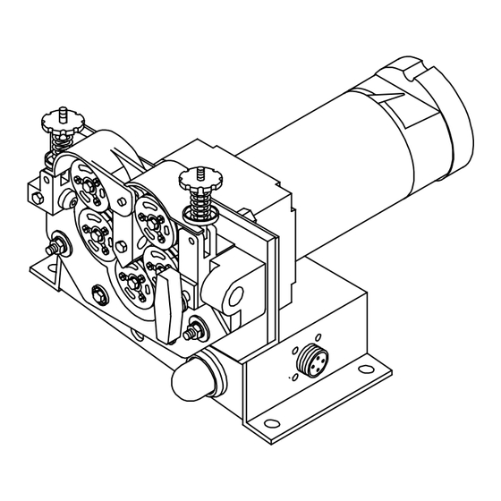
Summary of Contents for Miller Electric A1D-4RV
- Page 1 OM-1580C 134 192C May 1996 Processes Automatic Welding Description Wire Feeder A1D-4RV And A1D-4RW Visit our website at www.MillerWelds.com...
- Page 2 ISO 9001 Quality System Standard. service information for your particular model are also provided. Miller Electric manufactures a full line of welders and welding related equipment. For information on other quality Miller products, contact your local Miller distributor to receive the latest full line catalog or individual catalog sheets.
-
Page 3: Table Of Contents
TABLE OF CONTENTS SECTION 1 – SAFETY PRECAUTIONS - READ BEFORE USING 1-1. Symbol Usage ..............1-2. -
Page 5: Section 1 - Safety Precautions - Read Before Using
SECTION 1 – SAFETY PRECAUTIONS - READ BEFORE USING 1-1. Symbol Usage Means Warning! Watch Out! There are possible hazards with this procedure! The possible hazards are shown in the adjoining symbols. Y Marks a special safety message. Means “Note”; not safety related. 1-2. - Page 6 ARC RAYS can burn eyes and skin. Arc rays from the welding process produce intense visible and invisible (ultraviolet and infrared) rays that can burn eyes and skin. Sparks fly off from the weld. D Wear a welding helmet fitted with a proper shade of filter to protect your face and eyes when welding or watching (see ANSI Z49.1 and Z87.1 listed in Safety Standards).
-
Page 7: Additional Symbols For Installation, Operation, And Maintenance
1-3. Additional Symbols For Installation, Operation, And Maintenance FIRE OR EXPLOSION hazard. D Do not install or place unit on, over, or near combustible surfaces. D Do not install unit near flammables. D Do not overload building wiring – be sure power supply system is properly sized, rated, and protected to handle this unit. -
Page 8: Emf Information
1-5. EMF Information Considerations About Welding And The Effects Of Low Frequency Electric And Magnetic Fields Welding current, as it flows through welding cables, will cause electro- magnetic fields. There has been and still is some concern about such fields. However, after examining more than 500 studies spanning 17 years of research, a special blue ribbon committee of the National Research Council concluded that: “The body of evidence, in the committee’... -
Page 9: Section 2 - Specifications
SECTION 2 – SPECIFICATIONS 2-1. Specifications Specification Type Of Input Power 115 Volts DC Input Power Cord 12 in (305 mm) Overall Dimensions See Section 2-2 Weight 18 lb (7.9 kg) Wire Feed Speed Range 50 To 780 ipm (1.3 To 19.8 mpm) Wire Diameter Range .030 Thru 1/8 in (0.8 Thru 3.2 mm) 2-2. -
Page 10: Section 3 - Installation
SECTION 3 – INSTALLATION 3-1. Installing Wire Guides And Drive Rolls Side View Tools Needed: 7/16 in OM-1580 Page 6 When changing wire size or type, check drive roll and guide size (see Table 7-1). Wire Guide Securing Screw Inlet Wire Guide Intermediate Wire Guide Loosen wire guide screws. -
Page 11: Outlet Cable, Weld Cable, And Gas Connections
3-2. Outlet Cable, Weld Cable, And Gas Connections Connect To Positive (+) Weld Output Terminal On Welding Power Source For Reverse Polarity Weld Process Or Connect To Negative (–) Weld Output Terminal On Welding Power Source For Straight Polarity Weld Process. 3-3. -
Page 12: Section 4 - Operation
SECTION 4 – OPERATION 4-1. Safety Equipment 4-2. Sequence Of Operation Install & Thread & Feed Connect Welding Wire Equipment SECTION 5 – MAINTENANCE AND TROUBLESHOOTING 5-1. Routine Maintenance 3 Months Replace Unreadable Labels Section Clean Tighten Weld Terminals OM-1580 Page 8 Put On Turn On Personal Safety... -
Page 13: Aligning Drive Rolls And Wire Guides
5-2. Aligning Drive Rolls And Wire Guides CAUTION IMPROPER CLEARANCE between motor gear and drive gears on four-drive roll models can damage equipment. Maintain 0.003 in (0.076 mm) clearance between motor gear and drive gears. Gears may wear severely, bind, break, or cause erratic wire feed if proper clearance is not maintained. Horizontal Alignment Correct Alignment... -
Page 14: Brush Inspection And Replacement
Operation Module servo light on, Teach Check and secure servo warning light(s) connection. Pendant display on, servo warning light(s) off (A1D-4RV model only). Replace burned out servo warning light(s). OM-1580 Page 10 1/4 in (6 mm) -
Page 15: Section 6 - Electrical Diagrams
SECTION 6 – ELECTRICAL DIAGRAMS SA-134 193-B Figure 6-1. Circuit Diagram For A1D-4RV ST-174 873-A Figure 6-2. Circuit Diagram For A1D-4RW OM-1580 Page 11... -
Page 16: Section 7 - Parts List
For Drive Roll & Wire Guide Kits See Table 7-1 Includes Items 13-16 Includes Item 26 24 25 30 31 ST-134 750-B... - Page 17 ......Quantity Model A1D-4RV A1D-4RW ..... . .
- Page 18 ....... Quantity Model A1D-4RV A1D-4RW ..
- Page 19 Table 7-1. Drive Roll & Wire Guide Kits (4 Drive Roll) NOTE Base selection of drive rolls upon the following recommended usages: 1. V-Grooved rolls for hard wire. 2. U-Grooved rolls for soft and soft shelled cored wires. 3. U-Cogged rolls for extremely soft shelled wires (usually hard surfacing types). 4.
- Page 20 Notes OM-1580 Page 16...
- Page 21 Notes...
- Page 22 Notes...
- Page 23 Warranty Questions? Call LIMITED WARRANTY – Subject to the terms and conditions below, Miller Electric Mfg. Co., Appleton, Wisconsin, warrants 1-800-4-A-MILLER to its original retail purchaser that new Miller equipment sold for your local after the effective date of this limited warranty is free of defects in material and workmanship at the time it is shipped by Miller.
-
Page 24: Owner's Record
Parts) Circuit Diagrams Welding Process Handbooks File a claim for loss or damage during shipment. 2000 Miller Electric Mfg. Co. 6/00 Miller Electric Mfg. Co. An Illinois Tool Works Company 1635 West Spencer Street Appleton, WI 54914 USA International Headquarters–USA USA Phone: 920-735-4505 Auto-Attended USA &...


Need help?
Do you have a question about the A1D-4RV and is the answer not in the manual?
Questions and answers