Table of Contents
Advertisement
C O M M U N I C A T I N G
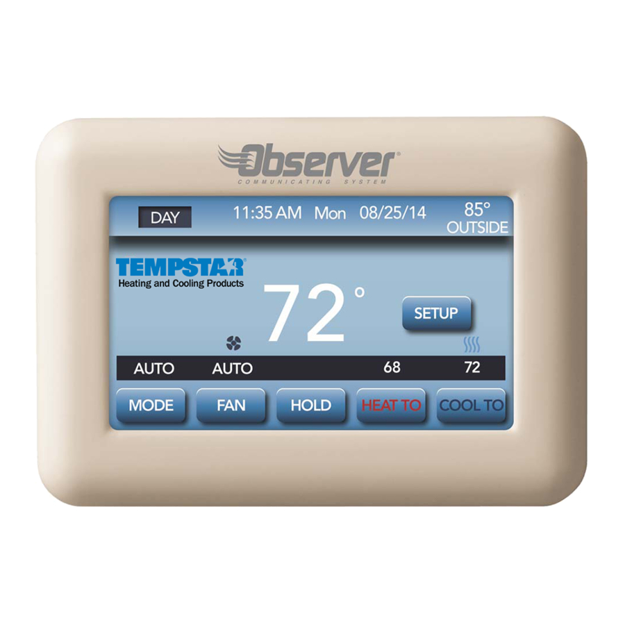
Communicating Wall Control
With Wi- -Fi
R
Installation Manual
TSTAT0201CW
U.S. Patent No. 7,243,004
U.S. Patent No. 7,775,452
All trademarks are the property of the respective owners.
®
Wi-Fi
is a registered trademark of the Wi-Fi Alliance Corporation.
R
S Y S T E M
Capability
616 01 1019 00 10/17/14
Advertisement
Table of Contents

Related Manuals for Observer TSTAT0201CW


Summary of Contents for Observer TSTAT0201CW
-
Page 1: Installation Manual
C O M M U N I C A T I N G S Y S T E M Communicating Wall Control With Wi- -Fi Capability Installation Manual TSTAT0201CW U.S. Patent No. 7,243,004 U.S. Patent No. 7,775,452 All trademarks are the property of the respective owners. ® Wi-Fi is a registered trademark of the Wi-Fi Alliance Corporation. -
Page 2: Table Of Contents
Safety Considerations ....... Introduction ......... Quick Start . - Page 3 Install/Service Menus – Communicating and Non-Communicating Mode ......Equipment Summary Menu ..... . . Service Menus .
- Page 4 Minimum Cooling Setpoint ......Maximum Heating Setpoint ......Outdoor Air Temperature Offset .
- Page 5 Defrost With Furnace ......Quiet Shift ....... . . Zones .
-
Page 6: Safety Considerations
Safety Considerations Improper installation, adjustment, alteration, service, main- tenance, or use can cause explosion, fire, electrical shock, or other conditions which may cause death, personal injury or property damage. Consult a qualified installer, service agency or your distributor or branch for information or assist- ance. -
Page 7: Introduction
All communicating furnaces or fan coils are variable-speed and multi-stage for maximum flexibility, efficiency, and com- fort. They support controlled humidification, dehumidification, and air quality control. Either an Observer communicating, or a standard 24VAC controlled outdoor unit may be used. When using conventional, single-stage outdoor units, the... - Page 8 Observer wall control will not be negatively affected by the network-related modifications, upgrades, or similar activity of the user’s Internet service provider or mobile device carrier service.
-
Page 9: Quick Start
Quick Start For first time installers, Quick Start will allow a quick start up of the Observer® Control before learning all the details of system operation. However, for the best possible comfort and operation refer to the Owner’s Manual. Set Day and Time To set the current time and date, press SETUP;... - Page 10 A14558 Under date, you can select the month, day, or year buttons; then use the ▲ and ▼ to select the appropriate date. . Un- der time, you can select the hour, minute, and am/pm; then use the ▲ and ▼ to select the appropriate time. You also have the option of selecting between a 12 HR or 24 HR clock format.
-
Page 11: Set Schedule For All Days
DONE to save and exit the information that you have entered. Set Schedule for All Days The Observer® Control gives you flexibility in how to create a comfort schedule. You can choose one schedule for all days; create a schedule for your work week and the week- end;... - Page 12 A14558 2. Press ▲ under “All Days”, then press EDIT. 616 01 1019 00...
- Page 13 3. Press PERIOD; then use the ▲ or ▼ to select the period to change. 4. Press START; then use the ▲ or ▼ to change the time the corresponding period starts. 5. Press HEAT TO; then use the ▲ or ▼ to change the desired heating temperature for that period.
-
Page 14: Installation
NOTE: See Owners manual for further details of setting up schedules. Installation Overview This instruction covers installation of the Observer® Control only. Physical installation instructions for the indoor and out- door equipment and accessories are provided with each unit. Setup, commissioning, operation, and troubleshooting of the communicating system are covered only in this installation instruction. -
Page 15: Check Equipment
All wiring must comply with national, local, and state codes. Wall Control The Observer® Control is the command center for the com- municating system. It should be located where it is easily accessible and visible to the adult homeowner or end user. -
Page 16: Remote Room Sensors
(for non-zoned system) A Remote Room Sensor (Part No. SYSTXIIRRS01) can be used with the Observer® Control to take the place of the control’s internal temperature sensor (This sensor is NOT the same as the Zone Temperature Sensor, even though the part numbers are similar). -
Page 17: Wiring Considerations
Wiring Considerations Ordinary thermostat wire is recommended. Use 22 AWG or larger for normal wiring applications. Continuous wire lengths over 100 ft. should use 20 AWG or larger. NOTE: The communicating bus wiring only requires a four-wire connection; however, it is good practice to run ther- mostat cable having more than four wires in the event of a damaged or broken wire during installation. - Page 18 3. Select Observer Control mounting plastic 4. Route wires through hole in mounting plastic. Level rear plastic against wall (for aesthetic value only - Observer Con- trol need not be level to operate properly) and mark wall through two mounting holes.
-
Page 19: Shielded Wire
Mount the assembly to the back-plate. NOTE: Once Observer Control is secured to wall with the back-plate assembly (snapped together), care must be taken not to bend or break the interlocking tabs when removing. - Page 20 3.90 5.20 0.97 Fig. 2 – Wall Control Assembly Pieces 616 01 1019 00...
-
Page 21: Humidifier Connection
Humidifier Connection A 24VAC bypass or fan powered humidifier may be installed. NOTE: Do Not Use a traditional humidistat to control humidi- fier operation. If a humidifier is installed, let the Observer® Control operate humidifier. Bypass Humidifiers A bypass humidifier is normally wired directly to the furnace or fan coil HUM and 24VAC COM terminals. -
Page 22: Commissioning
Observer® Control. The wall control will communicate and identify all communicating components in the system. When the Observer Wall Control is first powered up, it will display, Loading Graphics, then Select Function of this Unit. Next it will search for equipment, beginning with the indoor, then the outdoor, and remote room sensors. - Page 23 A14559 Once the indoor equipment, outdoor equipment, and zone panel (if applicable) have been found, the Installer will be asked to select if a humidifier is installed. NOTE: If the communicating indoor equipment (furnace or fan coil) cannot be found, the wall control will display the op- tion to enter THERMOSTAT DEMO MODE or to retry the search for equipment.
-
Page 24: Selecting Accessories
MOSTAT DEMO MODE if no communicating equipment is found. If a communicating indoor unit is found, but a communicating outdoor unit or relay board is not found, the installer will be prompted to select the outdoor type; either AC, Heat Pump, or NONE. - Page 25 616 01 1019 00...
-
Page 26: Equipment Summary
When all of the equipment is correct, press SAVE. Brand Selection After the commissioning of the Observer® Control, the in- staller will be prompted to select the appropriate brand. After the brand selection, or NO LOGO is made, the installer will have the opportunity to confirm the choice. -
Page 27: Current Software Version
HVAC equipment that are added to our prod- uct line; install these updates as required for the equipment installed as part of the Observer® Communicating System. Software updates will be made available through Internation- al Comfort Products distributors, for use by dealers. -
Page 28: Setting Up Remote Access And Wi-Fi® Connection
Wi-Fi® network to connect to the Inter- net. If the in-home Wi-Fi network or router is found to be in- compatible with the Observer wall control, an accessory Ob- server Wireless Access Point (NAXA00101WA) or any other compatible wireless router can be installed to establish Wi-Fi connectivity. - Page 29 SSID name Security Key A14519 When choosing the SSID to connect the Observer® wall control, select the myHVACxxxxxx SSID, as indicated on the NAXA00101wa label, from the list. (myHVAC is followed by the last 6 digits of your Wireless Access Point’s MAC address; see the label...
-
Page 30: Install/Service Menus - Communicating And Non-Communicating Mode
on the bottom of the TP-LINK® wireless access point). You may have to use the arrow at the bottom right of the SSID display screen to scroll to the next screen to find “myHVACxxxxxx”. A14518 Install/Service Menus – Communicating and Non-Communicating Mode The “INSTALLER CONFIGURATION”... -
Page 31: Equipment Summary Menu
NOTE: The INSTALL / SERVICE menu will automatically exit after 90 seconds of no activity. Equipment Summary Menu This screen shows indoor unit type and model number, out- door unit type (and model number if a communicating out- door unit), and any accessories that are installed are recog- nized. -
Page 32: Service Menus
Service Menus Status The Status screens will show all of the current operating pa- rameters of each installed piece of equipment. Heat Stage (Furnace): Displays stage of heat that the furnace is currently delivering. OFF, LOW, HIGH % capacity (modulating furnace only) Electric Heat (Fan Coil): Displays stages of electric heat that the fan coil is currently delivering. -
Page 33: Blower Rpm (Modulating Furnaces Only)
Blower RPM (Modulating furnaces only): Actual RPM feedback from indoor blower motor. Lockout Timer: If a lockout timer is active, this will show the current time val- ue. See equipment manual for details on lockout timers. Seconds Heat Pump/AC Status Stage: (Heat/Cool): Displays stage of heating or cooling that the Heat Pump/AC is delivering. -
Page 34: Lifetime Run History
Lifetime Run History The indoor unit and outdoor unit (if communicating) have the following histories: Cycle Counters Number of heat/cool/power cycles the unit has performed. Run Timers Lifetime hours of operation in heating, cooling, and how long the unit has been powered. 616 01 1019 00... -
Page 35: Filter Reminder
Filter Reminder Select the number of hours of fan operation after which the replace filter reminder shall appear. Off – The Replace Filter Reminder function is disabled 800-7200 hours – in 800 hour increments after which the re- minder shall appear Default = 3200 hours 616 01 1019 00... -
Page 36: Auto Mode Enable
Auto Mode Enable When Auto Mode is enabled (factory default) a change from heat to cool (or vice versa) will not occur until the current cycle is satisfied and an opposite mode demand has existed for 30 minutes. If the set-point is changed, the 30 minute timer is deleted. -
Page 37: Room Temperature Sensing
Remote Temperature Sensing The room air temperature can come from one of three sources: the local sensor in the wall control, the remote room air thermistor, or the average of the local and remote sensors. Local – use the local sensor in the wall control Remote –... -
Page 38: Reversing Valve
Reversing Valve For heat pump applications, the reversing valve will be active with heating or cooling operation. Heat Cool (default) 616 01 1019 00... -
Page 39: English/Metric Display
English/Metric Display Displaying temperature in English or Metric Values F – all temperatures and setpoints shown in degrees Fahrenheit C – all temperatures and setpoints shown in degrees Celsius Default = degrees F 616 01 1019 00... -
Page 40: Fan On With W
Fan on with W An option to turn the fan on with a call for heating OFF (default) 616 01 1019 00... -
Page 41: Cooling Lockout
Cooling Lockout When enabled, cooling will not be provided when the outside temperature is below 55º F. Off – Cooling is allowed at all outdoor air temperatures On – Cooling not allowed when outdoor air temperature is below 55º F. Default = Off 616 01 1019 00... -
Page 42: Auxiliary Heat Lockout
Auxiliary Heat Lockout With heat pump systems, the auxiliary heat will not be used when the outside temperature is above this setting. Off – The auxiliary heat can turn on whenever sufficient demand exists regardless of outside air temperature. 5º-55º F – Outside air temperature above which the auxili- ary heat will be inactive Default = Off 616 01 1019 00... -
Page 43: Heat Pump Lockout
Heat Pump Lockout With heat pump systems, the outside air temperature below which the heat pump will be locked out and only auxiliary heat will be used. Off – The heating cycle will always start with the heat pump regardless of the outside air temperature 5º-55º... -
Page 44: Minimum Cooling Setpoint
Minimum Cooling Setpoint The minimum cooling setpoint the user is allowed to set on the thermostat 52ºF to 90ºF (12ºC to 32ºC) Default = 52ºF (12ºC) 616 01 1019 00... -
Page 45: Maximum Heating Setpoint
Maximum Heating Setpoint The maximum heating setpoint the user is allowed to set on the thermostat 50ºF to 88ºF (10ºC to 30ºC) Default = 88ºF (30ºC) 616 01 1019 00... -
Page 46: Outdoor Air Temperature Offset
Outdoor Air Temperature Offset This option allows calibration (or deliberate mis-calibration) of the outdoor temperature. This offset is added to the actual temperature values. -5ºF to +5ºF (-3ºC to +3ºC) – Number of degrees added to the actual temperature value Default = 0 616 01 1019 00... -
Page 47: Room Air Temperature Offset
Room Air Temperature Offset -5ºF to +5ºF (-3ºC to +3ºC) – Number of degrees added to the actual temperature value Default = 0 616 01 1019 00... -
Page 48: Smart Recovery
Smart Recovery This feature applies to programmable operation only. The control will start recovery the selected number of minutes prior to schedule change in both heating and cooling mode as energy efficiently as possible. Off – at the programmed time, the setpoints shall be changed to the next programmed settings 30, 60 or 90 –... -
Page 49: Setpoint Deadband
Setpoint Deadband The minimum difference enforced between heating and cool- ing desired temperatures. This can allow one setting to “push” the other to maintain this difference. 2º to 6º - minimum number of degrees between the heat- ing and cooling setpoints Default = 2º... -
Page 50: Cycles Per Hour
Cycles Per Hour The maximum number of heating or cooling cycles per hour. 2 – The Y, Y2, W and W2 outputs shall be energized at most twice per hour 4 – The Y, Y2, W and W2 outputs shall be energized at most four times per hour 6 –... -
Page 51: Auto Changeover Timer
Auto Changeover Timer This feature designates the minimum number of minutes between heating and cooling operation when in auto mode. 5 to 30 minutes (5 minute increments) Default = 30 minutes 616 01 1019 00... -
Page 52: Time Between Fuel Types
Time Between Fuel Types The minimum amount of time the Y1 and Y2 output must be energized in heating before turning on the W1 output. 10 to 25 minutes (5 minute increments) Default = 15 minutes 616 01 1019 00... -
Page 53: Humidity Offset
Humidity Offset This option allows calibration (or deliberate mis-calibration) of the humidity sensor. This offset is added to the actual hu- midity value. The Test Humidifier option allows the Humidifi- er to be toggled on and off for testing. -10 to +10% Default = 0% 616 01 1019 00... -
Page 54: Programming On/Off
Programming On/Off This feature allows the thermostat to turn off the program- ming mode and operate as a non-programmable thermostat. Off – operates as a non-programmable thermostat On – allows program schedule to be set by user Default = On 616 01 1019 00... -
Page 55: Reset To Factory Defaults
Reset to Factory Defaults This feature allows the installer to return the thermostat to its factory default settings. The installer will need to hold the ▼ button down for 10 seconds to reset settings. 616 01 1019 00... -
Page 56: Dealer Info
NOTE: If the dealer inserts their contact information, includ- ing email address, on this screen, the user has the option to automatically send email Notifications and Service Re- minders to the dealer directly from the Observer® wall con- trol. 616 01 1019 00... -
Page 57: Service Reminder
Upon a initial startup dis- covery of the Observer® Control, DIP switch settings will be copied into the setup menu. Any changes can then be made from the Observer Control. -
Page 58: English/Metric Display
tion of the information that can be found in the INSTALLER SETUP menu. English/Metric Display ºF or ºC, (default = ºF) 616 01 1019 00... -
Page 59: Airflow
Airflow Upon a first time start-up of the Observer® Control, the fur- nace DIP switch settings will be copied to the furnace setup menu. Any changes can then be made from the Observer Control. Heating Airflow Furnace / Fancoil Heating Airflow Selects the airflow of the indoor unit when heating. -
Page 60: Heat Pump Heating Airflow
Heat Pump Heating Airflow COMFORT (default) -- Heat Pump airflow is varied depend- ing on outdoor temperature to maximize comfort. EFF 325 -- Fixed airflow used to achieve specified ratings. This is nominally 325 CFM/ton, but will vary if a 2--stage out- door unit is used. -
Page 61: Furnace Airflow (Capacity) Limiting
HIGH -- Minimum airflow during the dehumidify mode is in- creased to reduce duct and register sweating. Furnace Airflow (Capacity) Limiting The following settings allow the installer to restrict the fur- nace within certain minimum and maximum airflows. These airflows are converted to capacities. The Min and Max limits are determined by the equipment size. -
Page 62: Low Heat Rise
Low Heat Rise Set to ON if the system contains a bypass humidifier. The ON setting will increase the furnace low heat airflow. Off (default) 616 01 1019 00... -
Page 63: Defrost Interval
Defrost Interval Time interval at which defrost cycles can occur on a heat pump. 30 minutes 60 minutes 90 minutes 120 minutes (default) Auto-Defrost interval optimized by outdoor control (default for communicating HP) 616 01 1019 00... -
Page 64: Defrost With Furnace
Defrost With Furnace Choose whether furnace operates during defrost cycle. YES (default) Quiet Shift Turns on Quiet Shift function in 1-stage or 2-stage commu- nicating heat pumps. OFF (default) 616 01 1019 00... -
Page 65: Zones
Zones 616 01 1019 00... -
Page 66: Zone Weighting
Zone Weighting This configuration allows the installer to select the “size” of each zone. Typically, living areas are assigned a larger weight %, or importance factor, than bedrooms and smaller areas. The Zone weight affects what heating and cooling stages are used to condition the calling zones. If only one zone is calling for conditioning and that zones has a low weight, only low stage may be used. -
Page 67: Zone Airflow Control
Zone Names Allows the installer to assign a name to each zone. Zone Airflow Control Zone airflow control 616 01 1019 00... -
Page 68: Bypass
Bypass Select bypass amount for “zone X” Airflow Capacity This setting is used to limit the allowable zone airflow to prevent excessive air noise from being allowed into a zone. 616 01 1019 00... -
Page 69: Damper Type
Damper Type Power Open/Closed (default) Choose this selection for dampers that require power to open and power to close. Spring Return This type of damper requires continuous power to remain open, or to remain closed, depending on the type of damper that is installed. -
Page 70: Leaving Air Sensor (Las)
Zoning Enabled – Zoning system operates normally Zoning Disabled – Zoning operation is disabled. All dampers are driven to the open position. Temperature is controlled by the main Observer® Wall Control. Zone sen- sors are not used to control temperature when zoning is dis- abled. -
Page 71: Damper Timing
Damper Timing Selects the drive time for the dampers. Selections are 15, 30, 45, 60, 75, 105, and 120 seconds. Heat Recovery Maintenance Energizes the fan output at the specified speed for HRV applications DISABLED (Default) MEDIUM HIGH 616 01 1019 00... -
Page 72: Daughter Board
Daughter Board When non-communicating equipment is used, the daughter board may be needed. The daughter board provides outputs for non-communicating indoor equipment and non-communi- cating outdoor equipment. The daughter board should be used in the following applications: Non-communicating indoor unit with non-communi- cating outdoor unit. -
Page 73: Operational Information
Operational Information Auto Mode When Auto Mode is enabled (factory default) a change from heat to cool (or vice versa) will not occur until the current cycle is satisfied and an opposite mode demand has existed for 30 minutes. If the set-point is changed, the 30 minute timer is deleted. -
Page 74: Programming
Programming ON (default) - allows program schedule to be set by user. OFF - system becomes non--programmable Smart Recovery This feature applies to programmable operation only. The control will start recovery 90 minutes prior to schedule change in both heating and cooling mode. Refer to opera- tional information for more detail. -
Page 75: Appendix - Wiring Diagrams
Appendix - Wiring Diagrams *Note: R and C required for single stage communicating equipment. 616 01 1019 00... - Page 76 616 01 1019 00...
- Page 77 616 01 1019 00...
- Page 78 616 01 1019 00...
- Page 79 Non-Communicating Indoor Unit with Non-Communicating Outdoor Wall Control NAXA00101DB Green White Yellow Non-Communicating Outdoor Y/Y2 Non-Communicating Indoor Sensor 616 01 1019 00...
- Page 80 All trademarks are the property of the respective owners. ® Wi-Fi is a registered trademark of the Wi-Fi Alliance Corporation. Copyright 2014 International Comfort Products Lewisburg, TN 37091 USA 616 01 1019 00...
Need help?
Do you have a question about the TSTAT0201CW and is the answer not in the manual?
Questions and answers