Sign In
Upload
Download
Table of Contents
Contents
Add to my manuals
Delete from my manuals
Share
URL of this page:
HTML Link:
Bookmark this page
Add
Manual will be automatically added to "My Manuals"
Print this page
×
Bookmark added
×
Added to my manuals
Manuals
Brands
Flexit Manuals
Air Conditioner
S3 R
Operating instructions manual
Flexit S3 R Operating Instructions Manual
Air handling unit - rotor
Hide thumbs
1
Table Of Contents
2
3
4
5
6
7
8
9
10
11
12
13
14
15
16
17
18
19
20
21
22
23
24
25
26
27
28
29
30
31
32
33
34
35
36
37
38
39
40
page
of
40
Go
/
40
Contents
Table of Contents
Bookmarks
Table of Contents
Table of Contents
1 Dimensioned Drawings/Measures
Dimensioned Drawing S3 R
Dimensioned Drawing Sl4 R
Dimensioned Drawing S4 R/ S7 R
2 Mounting - Preparatory Work
Inspection/Maintenance
Required Space
Mounting Requirements
Recommended Sound Isolation - Horizontal Mounting
Recommended Sound Insulation - Wall Mounting
3 Installing S3 R
Location
4 Installing Sl4 R
Wall Mounting
Horizontal Mounting
5 Montering Av S4 R/S7 R
Wall Mounting
Horizontal Mounting
6 Connections/ Electrical Connection
Automatics
Supply Air Temperature Sencor (B1)
Temperature Sensor for Water Battery (B5)
External Components
7 Plumbing Works
Technical Spesifications Water Battery
Possible Valve Types
Possible Vent Motors
Placement of Duct Battery
Connections
8 General Pictures/System Drawings
S3 R
Sl4 R
S4 R/S7 R
9 Capasity and Sound Data
Capacity Diagram, Sound Data, Specifications - S3 R
Capacity Diagram, Sound Data, Specifications - Sl4 Re/Sl4 RW
Capacity Diagram, Sound Data, Specifications - Sl4 Re Ec/Sl4 RW Ec
Capacity Diagram, Sound Data, Specifications - S4 Re/S4 RW
Capacity Diagram, Sound Data, Specifications - S4 Re Ec/S4 RW Ec
Capacity Diagram, Sound Data, Specifications - S7 Re/S7 RW
Capacity Diagram, Sound Data, Specifications - S7 Re/S7 RW Ec
10 Installation of External Kitchen Hood
Technical Data
11 Adjusting the Kitchen Hood
Basic Ventilation
Forced Ventilation
Pressure Drop Measurement
12 Adjustment Curves External Kitchen Hood
Basic Ventilation S3 R/S3 RK
Forced Ventilation S3 R
Basic Ventilation Sl4 R/Sl4 R Ec
Forced Ventilation Sl4 R/Sl4 R Ec
13 Technical Spesifications
Technical Spesifictions S3 R
Technical Spesifictions Sl4 R
Technical Data S4 R
Technical Data S7 R
14 Final Check
15 Important Safety Instructions
16 Functional Description
Heating Elements
Operation Via Kitchen Hood (S3 R/Sl4 R)
17 Cleaning - Maintenance, S3 R
18 Cleaning - Maintenance Sl4 R
19 Cleaning - Maintenance S4 R/S7 R
20 Fault Location
21 Ce Declaration of Conformity
22 Product/Environmental Declaration
Advertisement
Quick Links
1
Dimensioned Drawing Sl4 R
2
Sl4 R
3
Cleaning - Maintenance Sl4 R
4
Fault Location
Download this manual
Flexit S3 R
Operating instructions
Air Handling Unit - Rotor
Sl4 R
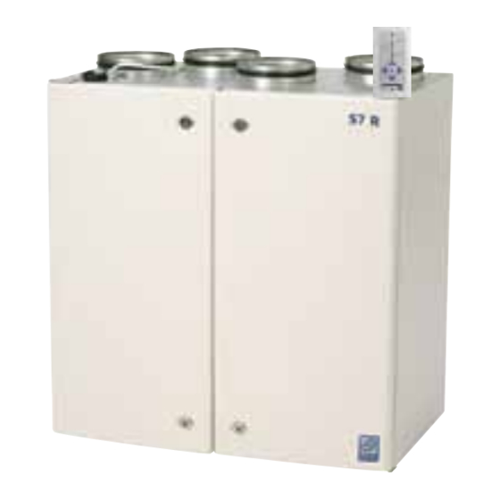
S4 R/S7 R
94273E-07
2011-01
Table of
Contents
Previous
Page
Next
Page
1
2
3
4
5
Advertisement
Table of Contents
Need help?
Do you have a question about the S3 R and is the answer not in the manual?
Ask a question
Questions and answers
Related Manuals for Flexit S3 R
Air Conditioner Flexit SL4 R Operating Instructions Manual
Air handling unit - rotor (40 pages)
This manual is also suitable for:
Sl4 r
S4 r/s7 r
Table of Contents
Save PDF
Print
Rename the bookmark
Delete bookmark?
Delete from my manuals?
Login
Sign In
OR
Sign in with Facebook
Sign in with Google
Upload manual
Upload from disk
Upload from URL


Need help?
Do you have a question about the S3 R and is the answer not in the manual?
Questions and answers