Table of Contents

Advertisement

Advertisement

Table of Contents
loading
Need help?

Need help?

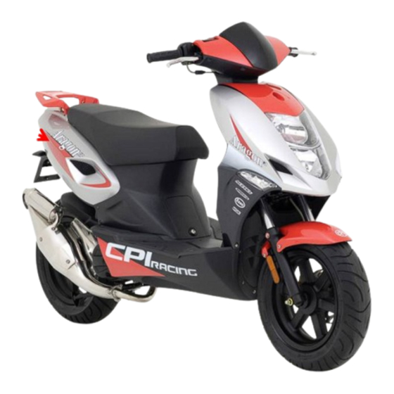
Do you have a question about the ARAGON and is the answer not in the manual?

Questions and answers

mark Smith
May 28, 2025

blowing head light bulbs and tail and park

1 comments:
Mr. Anderson
May 28, 2025

Possible causes for headlight, tail light, and parking light bulbs blowing on a CPI ARAGON include:

1. Overvoltage from the charging system – The correct battery charging voltage is 13.5 ± 0.5 V. If the voltage exceeds this range, it can damage bulbs.
2. Faulty voltage regulator – May allow excessive voltage to reach the bulbs.
3. Incorrect bulb wattage – Using bulbs with incorrect specifications can cause overheating and failure. The correct values are:
- Low beam: 55 W H1
- High beam: 55 W H1
- Position lamp: 5 W
- Rear/stop lamp: 21/5 W
4. Wiring issues – Short circuits or poor ground connections can lead to sudden voltage spikes.
5. Vibration or loose fittings – Can cause filament damage in bulbs.

Regular checks of the charging voltage and electrical connections can help prevent bulb failures.

This answer is automatically generated

Summary of Contents for CPI ARAGON

  • Page 3: Service Manual

    ARAGON GP, ARAGON, FORMULA R Service Manual PREFACE TABLE OF CONTENTS This workshop manual contains information about CHAPTERS GROUP common service, repair, and maintenance works for all systems of the model CPI JR. GENERAL INFORMATION The manual is subdivided in chapters, in which the vehicle systems in question are explained.
  • Page 5: General Information

    GENERAL INFORMATION GENERAL INFORMATION GI-2 WARNING AND SAFETY SYMBOLS GI-3 VEHICLE IDENTIFICATION NUMBERS GI-4 MAINTENANCE INSTRUCTIONS GI-5...
  • Page 6: General Information

    GENERAL INFORMATION GI-2 GENERAL INFORMATION CAUTION Suitable maintenance and repair proceedings are indispensable both for the safe and operationally reliable operation of a motor vehicle and for the personal safety of the mechanic. Many proceedings, techniques, tooling and components are known for the various maintenance works that are required for a vehicle, and the knowledge of motor vehicle technicians differs likewise.
  • Page 7: Warning And Safety Symbols

    GI-3 CAUTION The usage of low-quality fuels and lubricants, which do not correspond to the CPI specifications, can lead to severe engine and gear failures. Always use high-grade fuels and lubricants, which correspond to the specifications in the specifications chapter of this manual.
  • Page 8: Vehicle Identification Numbers

    11 and 12 (Formula R), it is stamped on the center front steering tube behind the legshield. In the case of versions 7-10 (Aragon / Aragon GP), the VIN ist stamped on the rear right-hand side of the frame. The cover must first be removed from there in order to make it visible.
  • Page 9: Maintenance Instructions

    GENERAL INFORMATION GI-5 MAINTENANCE INSTRUCTIONS PREPARING TOOLS AND MEASURING INSTRUMENTS Before staring any maintenance works make sure that all necessary tools and measuring instruments are available. SPECIAL TOOLS Use special tools, if stipulated in the chapter. REMOVAL OF ENGINE PARTS Before starting any mainrenance works try to track the fault cause.
  • Page 10 GENERAL INFORMATION GI-6 SPARE PARTS If parts have to be replaced, use original CPI spare parts only. REASSEMBLY If reassembling engine parts, precisely obey the instructions regarding defaults of tightening torques and other settings. The following parts always have to be replaced prior to reassembly.
  • Page 11 GENERAL INFORMATION GI-7 MAINTAINING THE ELECTRICAL SYSTEM 1. Prior to maintaining the electrical system, the ignition has to be switched off and the battery ground cable has to be disconnected. 2. To avoid slack, wiring harnesses have to be fixed with cable clamps or cable fastening ribbons.
  • Page 12 GENERAL INFORMATION GI-8 5. Do not drop relays, sensors, or other electric components and do not expose them to vibration. 6. Electric component parts built in the microcomputer or relay are sensitive to heat and can easily get damaged. If for maintenace works the temperature must be risen above 80 °C, those electric component parts have to be removed prior to maintenance.
  • Page 13 GENERAL INFORMATION GI-9 9. If snap-in connections have latching clips, those connections can be interrupted by pressing the clips down according to the directions specified in the adjacent drawing. 10. The latching clips are properly locked in place when you can hear a click noise.
  • Page 14 GENERAL INFORMATION GI-10 NOTES...
  • Page 15: Technical Data

    TECHNICAL DATA TD-1 TECHNICAL DATA SPECIFICATIONS TD 2 ARAGON GP 45 KM/H TD-2 ARAGON GP 30 KM/H TD-4 ARAGON GP 25 KM/H TD-6 ARAGON 45 KM/H TD-8 ARAGON 30 KM/H TD-10 ARAGON 25 KM/H TD-12 FORMULA R 45 KM/H TD-14...
  • Page 16: Specifications

    TECHNICAL DATA TD-2 SPECIFICATIONS Aragon GP 45km/h Engine: Nominal power (EEC) 2,9 / 6000 [kW/min Nominal torque (EEC) 4,9 / 6000 [Nm] Bore / Stroke 40 / 39,2 [mm] Compression ratio Compression pressure (hot) [bar/min Piston clearance, max. 0,085 [mm] Piston ring gap, max.
  • Page 17 TECHNICAL DATA TD-3 [Nm] Torques: [∅ mm] Front axle nut Rear axle nut Screw front fork bridge Screw brake calliper Screw handle bar Shock absorber lower fixing Engine mounting screw Gearbox cover screw Crankcase Cylinder head Flywheel CVT fixing nut Clutch fixing nut Clutch pads fixing nut Drain plug gearbox...
  • Page 18 TECHNICAL DATA TD-4 Aragon GP 30 km/h Engine: Nominal power (EEC) 1,4 / 5000 [kW/min Nominal torque (EEC) 3,5 / 3000 [Nm] Bore / Stroke 40 / 39,2 [mm] Compression ratio Compression pressure (hot) [bar/min Piston clearance, max. 0,085 [mm] Piston ring gap, max.
  • Page 19 TECHNICAL DATA TD-5 Torques: [Nm] [∅ mm] Front axle nut Rear axle nut Screw front fork bridge Screw brake calliper Screw handle bar Shock absorber lower fixing Engine mounting screw Gearbox cover screw Crankcase Cylinder head Flywheel CVT fixing nut Clutch fixing nut Clutch pads fixing nut Drain plug gearbox...
  • Page 20: Aragon Gp 25 Km/H

    TECHNICAL DATA TD-6 Aragon GP 25 km/h Engine: Nominal power (EEC) 1,4 / 5000 [kW/min Nominal torque (EEC) 3,5 / 3000 [Nm] Bore / Stroke 40 / 39,2 [mm] Compression ratio Compression pressure (hot) [bar/min Piston clearance, max. 0,085 [mm] Piston ring gap, max.
  • Page 21 TECHNICAL DATA TD-7 [Nm] Torques: [∅ mm] Front axle nut Rear axle nut Screw front fork bridge Screw brake calliper Screw handle bar Shock absorber lower fixing Engine mounting screw Gearbox cover screw Crankcase Cylinder head Flywheel CVT fixing nut Clutch fixing nut Clutch pads fixing nut Drain plug gearbox...
  • Page 22: Aragon 45 Km/H

    TECHNICAL DATA TD-8 Aragon 45 km/h Engine: Nominal power (EEC) 2,4 / 5900 [kW/min Nominal torque (EEC) 4,0 / 5400 [Nm] Bore / Stroke 40,0 / 39,2 [mm] Compression ratio Compression pressure (hot) [bar/min Piston clearance, max. [mm] Piston ring gap, max.
  • Page 23 TECHNICAL DATA TD-9 [Nm] Torques: [∅ mm] Front axle nut Rear axle nut Screw front fork bridge Screw brake calliper Screw handle bar Shock absorber lower fixing Engine mounting screw Gearbox cover screw Crankcase Cylinder head Flywheel CVT fixing nut Clutch fixing nut Clutch pads fixing nut Drain plug gearbox...
  • Page 24: Aragon 30 Km/H

    TECHNICAL DATA TD-10 Aragon 30 km/h Engine: Nominal power (EEC) 1,5 / 4500 [kW/min Nominal torque (EEC) 3,1 / 4500 [Nm] Bore / Stroke 40 / 39,2 [mm] Compression ratio Compression pressure (hot) [bar/min Piston clearance, max. [mm] Piston ring gap, max.
  • Page 25 TECHNICAL DATA TD-11 [Nm] Torques: [∅ mm] Front axle nut Rear axle nut Screw front fork bridge Screw brake calliper Screw handle bar Shock absorber lower fixing Engine mounting screw Gearbox cover screw Crankcase Cylinder head Flywheel CVT fixing nut Clutch fixing nut Clutch pads fixing nut Drain plug gearbox...
  • Page 26: Aragon 25 Km/H

    TECHNICAL DATA TD-12 Aragon 25 km/h Engine: Nominal power (EEC) 1,5 / 4500 [kW/min Nominal torque (EEC) 3,1 / 4500 [Nm] Bore / Stroke 40 / 39,2 [mm] Compression ratio Compression pressure (hot) [bar/min Piston clearance, max. [mm] Piston ring gap, max.
  • Page 27 TECHNICAL DATA TD-13 Torques: [Nm] [∅ mm] Front axle nut Rear axle nut Screw front fork bridge Screw brake calliper Screw handle bar Shock absorber lower fixing Engine mounting screw Gearbox cover screw Crankcase Cylinder head Flywheel CVT fixing nut Clutch fixing nut Clutch pads fixing nut Drain plug gearbox...
  • Page 28: Formula R 45 Km/H

    TECHNICAL DATA TD-14 Formula R 45 km/h Engine: Nominal power (EEC) 2,4 / 5900 [kW/min Nominal torque (EEC) 4,0 / 5400 [Nm] Bore / Stroke 40,0 / 39,2 [mm] Compression ratio 8,4:1 Compression pressure (hot) 7,85 / 600 [bar/min Piston clearance, max. 0,10 [mm] Piston ring gap, max.
  • Page 29 TECHNICAL DATA TD-15 Torques: [Nm] [∅ mm] Front axle nut Rear axle nut Front fork upper fixing Front fork lower fixing 20 / 30 Shock absorber upper fixing Shock absorber lower fixing Steering nut Engine mounting screw Crankcase Cylinder head Flywheel Drain plug gearbox Exhaust pipe...
  • Page 30: Formula R 30 Km/H

    TECHNICAL DATA TD-16 Formula R 30 km/h Engine: Nominal power (EEC) 1,5 / 4500 [kW/min Nominal torque (EEC) 3,1 / 4500 [Nm] Bore / Stroke 40,0 / 39,2 [mm] Compression ratio 8,4:1 Compression pressure (hot) 7,85 / 600 [bar/min Piston clearance, max. 0,10 [mm] Piston ring gap, max.
  • Page 31 TECHNICAL DATA TD-17 Torques: [Nm] [∅ mm] Front axle nut Rear axle nut Front fork upper fixing Front fork lower fixing 20 / 30 Shock absorber upper fixing Shock absorber lower fixing Steering nut Engine mounting screw Crankcase Cylinder head Flywheel Drain plug gearbox Exhaust pipe...
  • Page 32: Formula R 25 Km/H

    2000 ± 100 [min Automatic cold start equipment, stroke at 12V AC Working time [mm/5 min] [sec.] Fuel supply & adjustments: Carburetor VM CPI Main jet 47,5 Idling jet Position jet needle [from top] Float chamber level 14 ± 1...
  • Page 33 TECHNICAL DATA TD-19 [Nm] Torques: [∅ mm] Front axle nut Rear axle nut Front fork upper fixing Front fork lower fixing 20 / 30 Shock absorber upper fixing Shock absorber lower fixing Steering nut Engine mounting screw Crankcase Cylinder head Flywheel Drain plug gearbox Exhaust pipe...
  • Page 34: Technical Data Td

    TECHNICAL DATA TD-20 NOTES...
  • Page 35: Special Tools

    SPECIAL TOOLS ST-1 SPECIAL TOOLS DESCRIPTION AND USAGE ST-2...
  • Page 36: Crankcase 6

    Intended purpose Rotor puller BEN-AB-09 Disassembling the rotor from the crankshaft Disconnecting the crankcase and removing the crankshaft. Core disconnector CPI-0011-31 Disassembling the bearings from the crankshaft. Universal fixing tool DER-00005253240 Fixing the variomatic and the clutch Assembling bush CPI-000W-10...
  • Page 37 SPECIAL TOOLS ST-3 NOTES...
  • Page 39: Table Of Contents

    CARBURETOR FL-1 CARBURETOR SYSTEM OVERVIEW FL-2 MAINTENANCE NOTICE FL-3 TOOLS FL-4 FAULT TRACKING FL-4 CARBURETOR REMOVAL FL-5 CHECKING TH CHOKE FL-5 DISASSEMBLY FL-7 FLOAT CHAMBER LEVEL FL-7 SLIDE VALVE FL-7 FACTORY DEFAULT FL-8 REED-TYPE INLET-VALVE FL-10...
  • Page 40: System Overview

    CARBURETOR FL-2 SYSTEM OVERVIEW...
  • Page 41: Maintenance Notice

    CARBURETOR FL-3 MAINTENANCE NOTICE 1. Before maintaining the carburetor, the engine, the fuel supply, and the ignition system have to be in a faultless state. The carburetor can only properly adjusted and faults in the carburetor system can be detected when there are no mechanical defects in the engine or defectas in the fuel supply or in the ignition system.
  • Page 42: Tools

    CARBURETOR FL-4 TOOLS • Standard tools FAULT TRACKING Bad start behavior, stall, • Wrong idle speed adjustment • Mixture too rich, too lean • Air cleaner clogged or soiled • Choke system defective • Carburetor float chamber level wrongly adjusted A/F mixture too lean •...
  • Page 43: Carburetor Removal

    CARBURETOR FL-5 CARBURETOR REMOVAL Remove the helmet box. Remove the air filter container. Put out the cold start valve. Remove the throttle control cable. Remove the fuel line, the carburetor heating and the oil hose from the carburetor. Release the pipe clamp from the air cleaner snorkel and remove the carburetor.
  • Page 44: Disassembly

    CARBURETOR FL-6 Connect the cold start valve to a charged battery for about 5 min. Check additional bore picture). when able blow not ok: when you are not able to blow. DISASSEMBLY Release the fastening screws of the choke cable support bracket and remove the choke cable.
  • Page 45: Float Chamber Level

    CARBURETOR FL-7 FLOAT CHAMBER LEVEL Measure the float chamber with a caliper. Desired value: 18.5 mm Note that the float is entirely made of plastic. In case of any defects in this part, the float shall be replaced. Use a new sealing ring prior to mounting the float chamber cover.
  • Page 46: Factory Default

    (Aragon 30 km/h and 25 km/h variants; Formula R and Aragon: 25 km/h). In the case of the latter variants, the stop collar in the carburetor cover prevents the slide valve from entirely opening so that not the No stop collar full capacity of the A/F mixture can enter the carburetor.
  • Page 47 CARBURETOR FL-9 Mixture control screw For the proper adjustment of the idle speed the engine must have reached operating temperature. Make sure that the vehicle consumers (e.g. headlight) are switched on prior to modifying the A/F mixture in order to ensure that idle speed will not drop below a level required for the proper vehicle operation.
  • Page 48: Reed-Type Inlet-Valve

    CARBURETOR FL-10 REED-TYPE INLET VALVE Remove the carburetor and the intake manifold by releasing the hose clamp of the intake manifold. Check the intake manifold for crackings and fissures. Any ageing cracks in the intake manifold can be very harmful to the engine as foreign air can be suctioned and will cause leaning.
  • Page 49 CARBURETOR FL-11 NOTES...
  • Page 51: Oil Pump

    OIL PUMP LB-1 OIL PUMP SYSTEM OVERVIEW LB-2 REMOVAL LB-3 INSPECTION LB-3 INSTALLATION LB-3 BLEEDING LB-4...
  • Page 52: System Overview

    OIL PUMP LB-2 SYSTEM OVERVIEW...
  • Page 53: Removal

    OIL PUMP LB-3 REMOVAL Remove the underside paneling. Remove the fan cover, the impeller, and the generator. Remove the oil leads. After removing the supply line from the oil reservoir and the delivery line, which leads to the carburetor, both lines must be plugged with suitable plugs so that no oil can flow out.
  • Page 54: Bleeding

    OIL PUMP LB-4 Connect the oil leads to the pump. Hook in the control cable and adjust the cable play. The lever must have a free travel α of 5-8°. The allowable adjustment track to the full throttle position must be at least 70°. BLEEDING The pump body and the delivery line must be bleeded subsequent to the reinstallation of...
  • Page 55 OIL PUMP LB-5 NOTES...
  • Page 56: Cylinder Head 7

    CRANK DRIVE / CRANKCASE / CRANKSHAFT CR-1 CRANK DRIVE CRANKCASE CRANKSHAFT SYSTEM OVERVIEW CR-2 CYLINDER HEAD DISASSEMBLY CR-3 CYLINDER DISASSEMBLY CR-3 PISTON DISASSEMBLY CR-4 PISTON ASSEMBLY CR-7 CYLINDER ASSEMBLY CR-7 COMPRESSION PRESSURE TESTING CR-7 CRANKCASE / CRANKSHAFT CR-8 DISMANTLING THE ENGINE CASE CR-9 CRANKSHAFT CR-9...
  • Page 57: System Overview

    CRANK DRIVE / CRANKCASE / CRANKSHAFT CR-2 SYSTEM OVERVIEW...
  • Page 58: Cylinder Head Disassembly

    CRANK DRIVE / CRANKCASE / CRANKSHAFT CR-3 CYLINDER HEAD DISASSEMBLY Remove the helmet box and the seat. Remove the spark plug connector. Remove the muffler. Remove the carburetor and the air filter body. Remove the fan covers. Remove the spark plug. Loosen the cylinder head nuts.
  • Page 59: Piston Disassembly

    CRANK DRIVE / CRANKCASE / CRANKSHAFT CR-4 Adjust the piston to the bottom dead center before removing the cylinder. Carefully remove the cylinder and the base gasket. Fill the opening of the engine with a rag in order to avoid dirt or foreign material from entering the crankcase.
  • Page 60 Clearance limit value: Aragon Formula Aragon GP: Measure the ovality and the conicity: Ovality and conicity wear limit: Aragon / Formula R Ovality: 0.05 mm Conicity: 0.05 mm Aragon GP Ovality: 0.05 mm Conicity: 0.05 mm...
  • Page 61 CRANK DRIVE / CRANKCASE / CRANKSHAFT CR-6 Measure the piston pin boss crosswise. Wear limit: 10.05 mm Measure the piston pin crosswise at three spots. Wear limit: 9.95 mm When mounting new piston rings pay attention to whether the bevelled side of the piston rings Top piston ring faces upwards.
  • Page 62: Piston Assembly

    CRANK DRIVE / CRANKCASE / CRANKSHAFT CR-7 PISTON ASSEMBLY Put the oiled needle bearing into the connecting rod eye. Place the piston with its arrow orienting towards the opening. If the arrow is no longer detectable, then the piston ring gaps must always be opposite to the opening.
  • Page 63: Crankcase / Crankshaft

    CRANK DRIVE / CRANKCASE / CRANKSHAFT CRANK DRIVE / CRANKCASE / CRANKSHAFT CR-8 CR-8 CRANKCASE / CRANKSHAFT...
  • Page 64: Dismantling The Engine Case

    CRANK DRIVE / CRANKCASE / CRANKSHAFT CR-9 DISMANTLING THE ENGINE CASE Loosen and remove the engine case bolts. Separate the rightcrankcase half from the left one with a suitable puller. Press out the crankshaft from the left crankcase with the aid of a standard bearing and casing puller.
  • Page 65 CRANK DRIVE / CRANKCASE / CRANKSHAFT CR-10 Clamp the crankshaft between two test prods or place it on a vee-block for measuring. Measure the lateral runout with the aid of two dial gauges. The actual value is the half of the measured value.
  • Page 66: Assembling The Crankcase

    CRANK DRIVE / CRANKCASE / CRANKSHAFT CR-11 ASSEMBLING THE CRANKCASE Mount the crankshaft bearing in the left crankcase. The crankcase shall be heated up to approx. 120°C prior to driving in the bearing. Use temperature indicating chalk. Special tool: TKF900120 Mount the crankshaft bearing in the right crankcase.
  • Page 67 CRANK DRIVE / CRANKCASE / CRANKSHAFT CR-12 Clean the mating surfaces of the crankcase halves with a suitable solvent. Insert the guide sleeves and apply a thin layer of sealing compound to the mating surface of the left crankcase. Use Loctite® 518 sealing compound only! Heated up the right crankcase to approx.
  • Page 68 CRANK DRIVE / CRANKCASE / CRANKSHAFT CR-13 Mount the right crankshaft seal. Grease the shaft seal prior to mounting. Pay attention not to chock the shaft seal. The sealing lip must not get damaged! Special tool: 000W-10 Put together bowth crankcase halves with the crankshaft.
  • Page 69 CRANK DRIVE / CRANKCASE / CRANKSHAFT CR-14 NOTES...
  • Page 71 VARIOMATIC TRANSMISSION VT-1 VARIOMATIC TRANSMISSION SYSTEM OVERVIEW VT-2 LEFT ENGINE CASE COVER AND BELT-DRIVE REMOVAL VT-3 V-BELT VT-4 ROLLER WEIGHT MEASURING VT-5 ROLLER WEIGHTS CHECK VT-5 MOVABLE DRIVE FACE VT-6 CLUTCH SHOE UNIT VT-7 DISASSEMBLING THE CLUTCH UNIT VT-7 FAST PULLEY VT-8 CLUTCH SPRING VT-8...
  • Page 72: System Overview

    VARIOMATIC TRANSMISSION VT-2 SYSTEM OVERVIEW...
  • Page 73: Left Engine Case Cover And Belt-Drive Removal

    VARIOMATIC TRANSMISSION VT-3 LEFT ENGINE CASE COVER AND BELT-DRIVE REMOVAL Remove the engine case cover and the bushings. Loosen the securing nut of the centrifugal clutch and remove the entire clutch together with the V-belt. Torque: 35 – 40 Nm Special tool: ACC-ST8362070 Loosen securing...
  • Page 74: V-Belt

    VARIOMATIC TRANSMISSION VT-4 V-BELT Check the V-belt for break, fissures, aging, and other damages. Measure the width of the V-belt upper and lower side. Upper side wear limit: 16.5 mm Lower side wear limit: 12 mm Replace the drive belt if the wear limit is exceeded.
  • Page 75: Roller Weight Measuring

    VARIOMATIC TRANSMISSION VT-5 ROLLER WEIGHTS MEASURING Measure the diameter of the roller weights. Standard value: 15 mm Measure the height of the roller weight. Standard value: 12 mm ROLLER WEIGHTS CHECK Check the roller weights for wear and damage. Replace damaged or excessively worn roller weights.
  • Page 76: Movable Drive Face

    VARIOMATIC TRANSMISSION VT-6 MOVABLE DRIVE FACE Measure the diameter of the sintered metal sliding bearing. Wear limit: 21.10 mm Check the guide sleeve for scuffing, cracks etc. and replace it if necessary. Measure the diameter of the guide sleeve. Wear limit: 20.90 mm Measure the inside diameter of the clutch bell housing.
  • Page 77: Clutch Shoe Unit

    VARIOMATIC TRANSMISSION VT-7 CLUTCH SHOE UNIT. Measure the breadth of the clutch lining. Wear limit: 1.5 mm Check whether the linings adhere to the clutch and make sure they do not come loose. Check the individual clutch shoes for free movement.
  • Page 78: Fast Pulley

    Limit value: 32.90 mm CLUTCH SPRING Measure the free length of the clutch spring. Cluch spring length 67 mm 103 mm Aragon GP 25 km/h 30 / 45 km/h Aragon 25 / 30 km/h 45 km/h Formula R 25 / 30 km/h...
  • Page 79: Reassembly

    VARIOMATIC TRANSMISSION VT-9 Check the lock pins and the guide and the guide way in the movable pulley for damage or scoring. REASSEMBLY Assembly the clutch in reverse order. Grease all movable parts upon the reassembly of the clutch in order to ensure the free movement of the clutch component parts.
  • Page 80 VARIOMATIC TRANSMISSION VT-10 NOTES...
  • Page 81: Electrical System

    ELECTRICAL SYSTEM ES-1 ELECTRICAL SYSTEM GENERATOR REMOVAL ES-2 GENERATOR INSTALLATION ES-3 STARTER BATTERY CHECK ES-4 STARTER BATTERY CHARGING ES-4 LIGHT / CHARGING COIL ES-4 RESISTANCE CHECK (DUMMY CONSUMERS) ES-5 IGNITION COIL ES-5 MAGNETO IGNITION ES-6 PULSE GENERATOR ES-6 IGNITION TIMING ADJUSTMENT ES-6 STARTING MOTOR RELAY ES-7...
  • Page 82: Generator Removal

    ELECTRICAL SYSTEM ES-2 GENERATOR REMOVAL Remove the seat and the helmet box. Remove the blower hood. Loosen the impeller screws and remove the impeller. Immobilize the flywheel with a suitable tool and loosen the lock nut with a socket wrench. Torque: 35 Nm Special tool: ACC-00G05300011...
  • Page 83: Generator Installation

    ELECTRICAL SYSTEM ES-3 Remove the flywheel with a suitable puller. Special tool: AB-09 Disconnect the plug-in connection from the generator. Loosen the securing bolts of the stator assembly and remove the stator. GENERATOR INSTALLATION The generator shall be installed in reverse order.
  • Page 84: Starter Battery Check

    Discharged: 11 V Measure the charging voltage. 14 ± 0.5 V at5000 rpm STARTER BATTERY CHARGING The CPI JR comes with a maintenance-free starter battery. Use battery chargers that are suited for those battery types (e.g. Optimate / Tec Mate®...
  • Page 85: Resistance Check (Dummy Consumers

    ELECTRICAL SYSTEM ES-5 RESISTANCE CHECK (DUMMY CONSUMERS) Measure the resistance against ground. Desired value: 6.4 ± 0.2 Ω at 20°C ambient temperature IGNITION COIL Measure the primary coil winding with an ohmmeter. Desired value: 0.4 ~ 0.6 Ω at 20°C ambient temperature Measure the secondary coil winding with an ohmmeter.
  • Page 86: Magneto Ignition

    ELECTRICAL SYSTEM ES-6 MAGNETO IGNITION Checking the exciting coil: Disconnect the plug connection of the black/red cable measure black/red cable against ground with the aid of an ohmmeter. Desired value: 900 ± 100 kΩ at 20°C PULSE GENERATOR Disconnect the plug connections of the blue/white - green/white cables and measure the cable against ground with an ohmmeter.
  • Page 87: Starting Motor Relay

    ELECTRICAL SYSTEM ES-7 Measure the distance between the two markings. The overlap point is the actual TDC. Connect the stroboscopic lamp and start the engine. Turn the setting wheel of the of the stroboscopic lamp until the TDC marking on the magnet wheel is congruent to the TDC marking on the engine case.
  • Page 88: Fuel Level Sensor

    ELECTRICAL SYSTEM ES-8 FUEL LEVEL SENSOR Measure the resistance of the fuel level indicator. Float up: 5.5 Ω ~ 7 Ω Float down: 84 Ω ~ 86.5 Ω FUEL LEVEL INDICATOR Turn off the ignition and remove the fuel level sensor from the fuel tank. Move the float up and check whether the fuel level indicator also moves from “E”...
  • Page 89: Headlight Dimmer

    ELECTRICAL SYSTEM ES-9 HEADLIGHT DIMMER STARTER BUTTON Color Color Light Yello Dark Green/ Black blue w Red blue Yellow/Brown Position Position High beam Low beam Note that the plug connect- ions shall be disconnected prior to measuring. LIGHT CONTROL Color Yellow / Red Green / Red Brown / White...
  • Page 90: Wiring Diagrams

    ELECTRICAL SYSTEM ES-10 WIRING DIAGRAMS Aragon GP...
  • Page 91 ELECTRICAL SYSTEM ES-11 Aragon...
  • Page 92 ELECTRICAL SYSTEM ES-12 Formula R...
  • Page 93 ELECTRICAL SYSTEM ES-13 NOTES...

This manual is also suitable for:

Formula rAragon gp

Table of Contents

Save PDF