Table of Contents
Advertisement
Advertisement
Table of Contents

Subscribe to Our Youtube Channel
Related Manuals for Centurion Solo


Summary of Contents for Centurion Solo
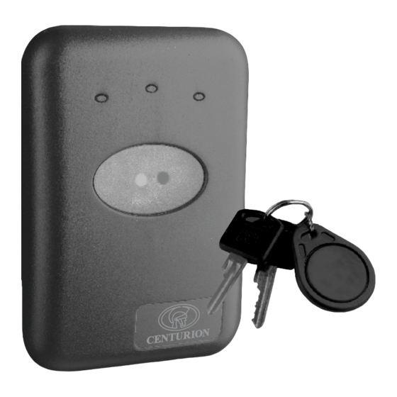
- Page 1 SOLO installation manual STAND-ALONE PROXIMITY ACCESS CONTROL SYSTEM...
- Page 2 © CENTURION SYSTEMS (PTY) LTD 2007 Centurion Systems (Pty) Ltd. reserves the right to make changes to the products described in this manual without notice and without obligation of Centurion Systems (Pty) Ltd. to notify any persons of any such revisions or changes. Additionally, Centurion Systems (Pty) Ltd. makes no representations or warranties with respect to this manual.
-
Page 3: Table Of Contents
ADD Tag: SOLO Specified Memory Location ........ - Page 4 HOW TO CONFIGURE THE DIFFERENT OPERATING PARAMETERS Overview ..............43 Turning the TAG BUZZER on or off .
-
Page 5: Product Overview
Mounting of the SOLO is very simple as it can be flush mounted into a 100mm x 50mm light switch box or surface mounted directly onto the wall. In addition, the unit can be purchased with an anti-knock shield, providing better protection when surface mounting the unit externally or to a gooseneck. -
Page 6: Specifications
Specifications Specifications Physical Supply Voltage 10 - 12V AC 12-15V DC Standby Current 50mA Maximum Current 180mA Operating Temperature -20°C to 50°C Operating Humidity 0-90% non condensing Tag Frequency 13.56 MHz Housing Material ABS UV Stabilised Degree of Protection IP 55 Dimensions Surface Mount 129H x 90W x 29D... -
Page 7: Tools And Equipment Required
Tools and Equipment Required Tools and Equipment Required Star Screwdriver Long Nose Pliers 0 and 1 point Flat Screwdriver - 2.5mm point Jewellers Type Side Cutters Tape Measure Silicon Cable: 0.20mm² 0.50mm² 0.75mm² Level Level Masonry Bit Drilling Machine Multi-Meter (hammer action) Page 7... -
Page 8: Quik Wiring Diagram
Quik Wiring Diagram Quik Wiring Diagram Jumper 2 Jumper 2 Read range will be affected if not correctly set Power Supply Jumper 2 Jumper 2 10-12V AC 12-15V DC Jumper 1 Jumper 1 NB: Wire Link must be fitted if Typical Door Sense Potential... -
Page 9: Quik Add: New Installation
Tags will be added to the SOLO Reader sequentially from Memory Locations 00 to 50. The first two Tags presented to the SOLO Reader will become the Master Tags in Memory Locations 00 and 01. It is recommended that the first Master Tag be kept in a safe and secure location. -
Page 10: Quik Add: Existing Installation
Quik Add - Existing Installation Please Note: Tags will be added sequentially to the empty Memory Locations of the SOLO Reader. Previous Memory Locations will not be overwritten. To ABORT wait for ± 60 seconds for the SOLO to RESET Present &... -
Page 11: Quik Delete
Quik Delete - All Tags Please Note: This option will remove all tags from the SOLO Reader's memory but will not change any of the Configuration Settings or Timer Values. To ABORT wait for ± 60 seconds for the SOLO to RESET... -
Page 12: Quik Parameter Factory Default
All Configuration Settings and Timer Values will be defaulted to factory settings. No Tags will be removed from the SOLO Reader memory. To ABORT wait for ± 60 seconds for the SOLO to RESET ORANGE GREEN Present &... - Page 13 SOLO reader. Mounting the Reader The SOLO Prox reader is available in a flush mount kit and a surface mount kit. When flush mounting, the reader adapts directly to a standard 100mm x 50mm (4" x 2") light switch backing box which allows the unit to sit flat against the wall.
- Page 14 Surface Mount Clip the plastic spacers onto the Place the mounting template located Using the slots provided in the in the centre of this document at the back of the mounting frame ensuring mounting holes, adjust the reader required height ensuring that it is that they are correctly orientated to base to be perfectly vertical.
- Page 15 Optional cable tie Jumper 2 Jumper 1 If the additional cable tie was used, Ensure Jumpers 1 and 2 are Slide the back cover onto the make certain that it is also tightened. correctly positioned - refer to controller housing.
-
Page 16: Wiring Diagrams
Wiring Diagrams Identification of Terminals The following figure shows the location of the terminal block on the SOLO controller, as well the position of Jumper 1 and Jumper 2. Refer to page 19 for an explanation of these jumpers. The table below details each terminal. - Page 17 Solenoid - Electric Door Lock Wire power to lock separately from the reader CP84SM Mains 1 2 V 0.5mm² B a t t e cable Entrance/exit Door 0.75mm² cable Jumper 1 Jumper 1 NB: Wire Link must be fitted if door sense facility is not being used.
- Page 18 Gate Operator / Traffic Barrier Power Supply and/or Battery Backup Jumper 1 Jumper 1 NB: Wire Link must be fitted if Door Sense Facility is not being used. Fig 5. Gate Operator/ Traffic Barrier Gate Operator / Traffic Barrier via SmartSwitch II Normally-open pushbutton Fig 6.
- Page 19 Jumper 2 - Wall or Steel Mounting The read range of the SOLO reader can be optimised whether it is being mounted onto a steel surface (ie. inside the SOLO anti-knock shield or directly onto a steel post or pedestal) or wood / masonry surface (wooden door frame or plastered/plain brick/stone wall*) *flush mounting into a 4"...
-
Page 20: Overview Of User Interface
Identification of Tags Find Master Tags It is important to note that the SOLO system can accommodate two MASTER tags used for administering the unit. The primary MASTER tag is stored in memory location 00 and the secondary in 01. -
Page 21: Find Master Tags
ON briefly Present and REMOVE the Master Tag in Memory Location 01 BOTTOM GREEN LIGHT will turn ON briefly The SOLO Reader will remain in Normal RUN MODE if Master Tags are presented for less than 5 seconds. Page 21... -
Page 22: Find User Tag Memory Location
The Memory Location will be repeatedly shown for as long as the User Tag is presented to the SOLO Reader. Ensure that the Master Tag is not presented to the SOLO Reader for longer than 5 seconds or Programme Mode will be entered. ... - Page 23 EXAMPLE How to find User Tag Memory Location Graphical Instructions Written Instructions Example: User Tag in Memory Location 03 TOP GREEN LIGHT will SHORT FLASH to indicate 0 TENS TOP RED LIGHT will FLASH 3 TIMES to indicate 3 UNITS Short Flash = 0 Flash x 3 (TENS)
-
Page 24: Overview
Overview The SOLO Reader is capable of storing a total of 51 Zap Tags in Memory Locations 00 to 50. Memory Locations 00 and 01 are reserved for the two Master Tags, either of which is required for adding and deleting Tags, and configuring the SOLO Reader. - Page 25 Add Tag - SOLO Specified Memory Locations Please Note: Tags will be added sequentially to the empty Memory Locations of the SOLO Reader. Previous Memory Locations will not be overwritten. To ABORT wait for ± 60 seconds for the SOLO to RESET Present &...
- Page 26 Both BOTTOM GREEN LIGHT ON and BOTTOM RED LIGHT ON Present and remove the Master Tag The SOLO Reader will enter normal RUN MODE It is recommended that the attached Memory Location allocation and Parameter settings form be updated. Counting examples for Memory Locations may be found on page 25...
- Page 27 EXAMPLE How to use the LEDs to select Memory Locations Graphical Instructions Written Instructions Example: Value set to 03 TOP GREEN LIGHT will SHORT FLASH to indicate 0 TENS TOP RED LIGHT will FLASH 3 TIMES to indicate 3 UNITS Short Flash = 0 Flash x 3 (TENS)
- Page 28 Add Tag - USER Specified Memory Locations Please Note: Previous Memory Locations will not be overwritten. To ABORT wait for ± 60 seconds for the SOLO to RESET Present & Present & Remove Remove ORANGE GREEN Hold Master Tag...
- Page 29 To select To move forward to next Memory Location available Memory Location Only BOTTOM RED LIGHT ON Present and HOLD the Master Tag Only BOTTOM GREEN LIGHT ON Present and remove the Master Tag On TOP RED LIGHT count number of flashes required for UNITS value.
- Page 30 Both BOTTOM GREEN LIGHT ON and BOTTOM RED LIGHT ON Present and remove the Master Tag The SOLO Reader will enter normal RUN MODE It is recommended that the attached Memory Location allocation and Parameter settings form be updated. Counting examples for Memory Locations may be found on page 25...
-
Page 31: Overview
2. Delete Tag - via Memory Location A benefit of the SOLO Reader is the ability to selectively delete user tags from the system. Provided that a record has been kept of the memory location of the user whose tag is required to be deleted, by following this procedure, this tag can be deleted without affecting any of the other tags in the system. - Page 32 Delete Tag via Memory Location (Tag not available) Please Note: Memory Location of Tag is required for this process To ABORT wait for ± 60 seconds for the SOLO to RESET ORANGE GREEN Present & Hold Master Tag...
- Page 33 Both BOTTOM GREEN LIGHT ON and BOTTOM RED LIGHT ON Present and remove the Master Tag The SOLO Reader will enter normal RUN MODE It is recommended that the attached Memory Location allocation and Parameter settings form be updated. Counting examples for Memory Locations may be found on page 32...
- Page 34 EXAMPLE How to use the LEDs to select Memory Locations Graphical Instructions Written Instructions Example: Value set to 03 TOP GREEN LIGHT will SHORT FLASH to indicate 0 TENS TOP RED LIGHT will FLASH 3 TIMES to indicate 3 UNITS Short Flash = 0 Flash x 3 (TENS)
-
Page 35: Delete Tag: Tag Available
Delete Tag (Tag available) Please Note: To ABORT wait for ± 60 seconds for the SOLO to RESET Present & ORANGE GREEN Hold Master Tag Present & Remove BOTTOM BOTTOM Existing User Tag GREEN Graphical Instructions Written Instructions Present and HOLD either Master Tag until... - Page 36 Repeat from Step 8 above for other Tags as required Present and remove the Master Tag The SOLO Reader will enter normal RUN MODE It is recommended that the attached Memory Location allocation and Parameter settings form be updated. Counting examples for Memory Locations may be found on page 32...
- Page 37 Replacing Master Tag in Memory Location 01 (Secondary Master Tag) Please Note: Master Tag in Memory Location 00 must be used for this procedure. To ABORT wait for ± 60 seconds for the SOLO to RESET Present & Present & Remove ORANGE GREEN...
- Page 38 BUZZER will sound to indicate a successful addition. Present and REMOVE either Master Tag The SOLO Reader will enter normal RUN MODE It is recommended that the attached Memory Location allocation and Parameter settings form be updated. Please note that the primary Master Tag (memory location 00) has greater access rights than the secondary Master Tag (memory location 01).
- Page 39 Replacing Master Tag in Memory Location 00 (Primary Master Tag) Please Note: Master Tag in Memory Location 01 must be used for this procedure. To ABORT wait for ± 60 seconds for the SOLO to RESET Present & Present & Remove ORANGE GREEN...
- Page 40 Present and remove the Master Tag Top lights will FLASH Present and remove the NEW Master Tag The SOLO Reader will enter normal RUN MODE It is recommended that the attached Memory Location allocation and Parameter settings form be updated.
- Page 41 All Tags will be deleted from the SOLO Reader. All parameters will be restored to the Factory Default Settings. To ABORT wait for ± 60 seconds for the SOLO to RESET Present & Present & Remove ORANGE...
- Page 42 Present and remove the Master Tag Selected Memory Location 00 indicated by TOP GREEN LIGHT Short Flash and TOP RED LIGHT Short Flash Short Flash = 0 Short Flash = 0 (TENS) (UNITS) Only BOTTOM GREEN LIGHT ON Present and HOLD the Master Tag All the lights begin to Flash Continue to HOLD the Master Tag WAIT for all the lights to turn OFF...
-
Page 43: Overview
If turned ON, the DOOR FORCED ALARM OUTPUT option activates the ALARM output immediately † when the access point being controlled by the SOLO Reader has been forced open . The ALARM terminal provides a common ground Open Collector output capable of sinking a MAXIMUM current of 50mA at 17 volt DC, and can be connected to a third party alarm system, external siren, etc. - Page 44 The SMARTSWITCH II will only operate correctly if the SMARTSWITCH II option is turned on AND the relay selection jumper on the SOLO Reader is fitted to the correct pins. Refer to Figure 1 on page 8 for the connection method.
-
Page 45: Turning The Tag Buzzer On Or Off
Turning the TAG BUZZER ON or OFF Please Note: To ABORT wait for ± 60 seconds for the SOLO to RESET ORANGE GREEN Present & Hold Master Tag BOTTOM BOTTOM GREEN Graphical Instructions Written Instructions Present and HOLD either Master Tag until... - Page 46 Present and remove the Master Tag The SOLO Reader will enter normal RUN MODE It is recommended that the attached Memory Location allocation and Parameter settings form be updated. Tips and tricks for SOLO Configuration Menu on page 44 Page 46...
- Page 48 NORMAL MODE For Tag Location, present & HOLD Tag for ± 3 seconds NORMAL enter PROGRAMMING PROGRAMMING MODE MODE TURBO PROGRAMMING MODE AUTO-LEARN LIMITED TIME AUTO-LEARN UNLIMITED TIME ADVANCED USER MENU MAP...
- Page 50 DRILL 5mm CONDUIT CONDUIT LOCATION LOCATION RECOMMENDED RECOMMENDED DO NOT ALLOW CABLE ACCESS THROUGH THIS AREA PREFERRED PREFERRED CONDUIT CONDUIT LOCATION LOCATION DRILL 5mm...
- Page 51 This mounting template is to be used when performing a surface mount installation. (Remove template from book) When planning where to locate the unit, it is important to consider the cable entry position. Do not allow cables to enter the unit through the centre area as this will interfere with assembly of the unit after installation.
- Page 53 QUIK ADD ADD TAG DELETE TAG TAG BUZZER CONFIG EXTERNAL ALARM EXTERNAL ALARM DOOR FORCED DOOR FORCED LOCAL ALARM DOOR FORCED EXTERNAL ALARM DOOR OPEN LOCAL ALARM DOOR OPEN SMARTSWITCH II ON or OFF RELAY TIMERS DOOR OPEN PRE-WARN DOOR OPEN ALARM DOOR FORCED ALARM HOLD OFF...
-
Page 55: Turning The Free Exit On Or Off
Turning the FREE-EXIT ON or OFF ORANGE GREEN Present & Hold Master Tag BOTTOM BOTTOM GREEN Graphical Instructions Written Instructions Present and HOLD either Master Tag until all lights turn ON Observe Lights Remove the Master Tag Observe Top green light will remain on Lights Observe Only BOTTOM RED LIGHT ON... - Page 56 Present and remove the Master Tag The SOLO Reader will enter normal RUN MODE It is recommended that the attached Memory Location allocation and Parameter settings form be updated. Tips and tricks for SOLO Configuration Menu on page 44 Page 48...
-
Page 57: Turning The Door Forced Alarm Output On Or Off
Turning DOOR FORCED ALARM OUTPUT ON or OFF Please Note: To ABORT wait for ± 60 seconds for the SOLO to RESET ORANGE GREEN Present & Hold Master Tag BOTTOM BOTTOM GREEN Graphical Instructions Written Instructions Present and HOLD either Master Tag until... - Page 58 Present and remove the Master Tag The SOLO Reader will enter normal RUN MODE It is recommended that the attached Memory Location allocation and Parameter settings form be updated. Tips and tricks for SOLO Configuration Menu on page 44 Page 50...
- Page 59 Turning DOOR FORCED ALARM BUZZER ON or OFF ORANGE GREEN Present & Hold Master Tag BOTTOM BOTTOM GREEN Graphical Instructions Written Instructions Present and HOLD either Master Tag until all lights turn ON Observe Lights Remove the Master Tag Observe Top green light will remain on Lights Observe...
- Page 60 Present and remove the Master Tag The SOLO Reader will enter normal RUN MODE It is recommended that the attached Memory Location allocation and Parameter settings form be updated. Tips and tricks for SOLO Configuration Menu on page 44 Page 52...
-
Page 61: Turning The Door Open Alarm Output On Or Off
Turning DOOR OPEN ALARM OUTPUT ON or OFF Please Note: To ABORT wait for ± 60 seconds for the SOLO to RESET ORANGE GREEN Present & Hold Master Tag BOTTOM BOTTOM GREEN Graphical Instructions Written Instructions Present and HOLD either Master Tag until... - Page 62 Only BOTTOM RED LIGHT ON Present and remove the Master Tag Top green and top red light will turn on Only BOTTOM RED LIGHT ON Present and remove the Master Tag Top orange light will turn on Only BOTTOM RED LIGHT ON Present and remove the Master Tag Top orange and top red light will turn on...
- Page 63 Present and remove the Master Tag The SOLO Reader will enter normal RUN MODE It is recommended that the attached Memory Location allocation and Parameter settings form be updated. Tips and tricks for SOLO Configuration Menu on page 44 Page 55...
- Page 64 Turning DOOR OPEN ALARM BUZZER ON or OFF Please Note: To ABORT wait for ± 60 seconds for the SOLO to RESET ORANGE GREEN Present & Hold Master Tag BOTTOM BOTTOM GREEN Graphical Instructions Written Instructions Present and HOLD either Master Tag until...
- Page 65 Only BOTTOM RED LIGHT ON Present and remove the Master Tag Top green and top red light will turn on Only BOTTOM RED LIGHT ON Present and remove the Master Tag Top orange light will turn on Only BOTTOM RED LIGHT ON Present and remove the Master Tag Top orange and top red light will turn on...
- Page 66 Present and remove the Master Tag The SOLO Reader will enter normal RUN MODE It is recommended that the attached Memory Location allocation and Parameter settings form be updated. Tips and tricks for SOLO Configuration Menu on page 44 Page 58...
-
Page 67: Turning The Smartswitch Ii On Or Off
Turning SMARTSWITCH II ON or OFF Please Note: To ABORT wait for ± 60 seconds for the SOLO to RESET ORANGE GREEN Present & Hold Master Tag BOTTOM BOTTOM GREEN Graphical Instructions Written Instructions Present and HOLD either Master Tag until... - Page 68 Only BOTTOM RED LIGHT ON Present and remove the Master Tag Top green and top red light will turn on Only BOTTOM RED LIGHT ON Present and remove the Master Tag Top orange light will turn on Only BOTTOM RED LIGHT ON Present and remove the Master Tag Top orange and top red light will turn on...
- Page 69 Present and remove the Master Tag The SOLO Reader will enter normal RUN MODE It is recommended that the attached Memory Location allocation and Parameter settings form be updated. Tips and tricks for SOLO Configuration Menu on page 44 Page 61...
-
Page 70: Overview
Timers Menu Overview The Timers Menu of the SOLO Reader allows five timer values to be changed individually as required for each installation. The various Timer values have been factory preset to the most commonly used values. FACTORY DEFAULT TIMER VALUES... - Page 71 5. Timer Option 5 - Door Forced Alarm (Factory Default - Latched) The Door Forced Alarm time controls the length of time for which the Door Forced Alarm activates. See Table 5 below for various settings. 6. Timer Option 6 - Hold Off Time (Factory Default - 0 Seconds) The Hold Off time is only used when door status monitoring is required in conjuction with a pre-impulse strike lock.
- Page 72 EXAMPLE How to use the LEDs to set the various Timers Graphical Instructions Written Instructions Example: Timer Value set to 5 Seconds TOP ORANGE LIGHT will SHORT FLASH to indicate 0 HUNDREDS TOP GREEN LIGHT will SHORT FLASH to indicate 0 TENS 0 0 5 TOP RED LIGHT will FLASH 5 TIMES Short Flash = 0...
-
Page 73: Change Relay Time
Please Note: Time selectable in 1 second increments from 1 to 255 seconds. For LATCHING RELAY select 255 To ABORT wait for ± 60 seconds for the SOLO to RESET ORANGE GREEN Present & Hold Master Tag... - Page 74 Top red light will turn on Only BOTTOM GREEN LIGHT ON Present and remove the Master Tag TOP ORANGE LIGHT will FLASH to indicate HUNDREDS TOP GREEN LIGHT will FLASH to indicate TENS TOP RED LIGHT will FLASH to indicate UNITS Hundreds Tens Units...
- Page 75 Both BOTTOM GREEN LIGHT ON and BOTTOM RED LIGHT ON Present and remove the Master Tag The SOLO Reader will enter normal RUN MODE It is recommended that the attached Memory Location allocation and Parameter settings form be updated. Examples for setting timer values may be found on page 64...
-
Page 76: Change Door Open Time
Time selectable in 1 second increments from 1 to 255 seconds. For INFINITE DOOR OPEN TIME select 255 To ABORT wait for ± 60 seconds for the SOLO to RESET ORANGE GREEN Present & Hold Master Tag... - Page 77 Top red light will turn on Only BOTTOM RED LIGHT ON Present and remove the Master Tag Top green light will turn on Only BOTTOM GREEN LIGHT ON Present and remove the Master Tag TOP ORANGE LIGHT will FLASH to indicate HUNDREDS TOP GREEN LIGHT will FLASH to indicate TENS TOP RED LIGHT will FLASH...
- Page 78 Both BOTTOM GREEN LIGHT ON and BOTTOM RED LIGHT ON Present and remove the Master Tag The SOLO Reader will enter normal RUN MODE It is recommended that the attached Memory Location allocation and Parameter settings form be updated. Examples for setting timer values may be found on page 64...
-
Page 79: Change Door Open Pre-Warn Time
Time selectable in 1 second increments from 1 to 255 seconds. For INFINITE DOOR OPEN PRE-WARN TIME select 255 To ABORT wait for ± 60 seconds for the SOLO to RESET ORANGE GREEN Present & Hold Master Tag... - Page 80 Top red light will turn on Only BOTTOM RED LIGHT ON Present and remove the Master Tag Top green light will turn on Only BOTTOM RED LIGHT ON Present and remove the Master Tag Top green and Top red light will turn on Only BOTTOM GREEN LIGHT ON Present and remove the Master Tag TOP ORANGE LIGHT will FLASH...
- Page 81 Both BOTTOM GREEN LIGHT ON and BOTTOM RED LIGHT ON Present and remove the Master Tag The SOLO Reader will enter normal RUN MODE It is recommended that the attached Memory Location allocation and Parameter settings form be updated. Examples for setting timer values may be found on page 64...
-
Page 82: Change Door Open Alarm Time
Time selectable in 1 second increments from 1 to 255 seconds. For LATCHED DOOR OPEN ALARM select 255 To ABORT wait for ± 60 seconds for the SOLO to RESET ORANGE GREEN Present & Hold Master Tag... - Page 83 Top red light will turn on Only BOTTOM RED LIGHT ON Present and remove the Master Tag Top green light will turn on Only BOTTOM RED LIGHT ON Present and remove the Master Tag Top green and Top red light will turn on Only BOTTOM RED LIGHT ON Present and remove the Master Tag Top orange light will turn on...
- Page 84 Both BOTTOM GREEN LIGHT ON and BOTTOM RED LIGHT ON Present and remove the Master Tag The SOLO Reader will enter normal RUN MODE It is recommended that the attached Memory Location allocation and Parameter settings form be updated. Examples for setting Timer Values may be found on page 64...
-
Page 85: Change Door Forced Alarm Time
Change Door Forced Alarm Time Please Note: Time selectable in 1 second increments from 1 to 255 seconds. For LATCHED DOOR FORCED ALARM select 255 ORANGE GREEN Present & Hold Master Tag BOTTOM BOTTOM GREEN Graphical Instructions Written Instructions Present and HOLD either Master Tag until all lights turn ON Observe... - Page 86 Top red light will turn on Only BOTTOM RED LIGHT ON Present and remove the Master Tag Top green light will turn on Only BOTTOM RED LIGHT ON Present and remove the Master Tag Top green and Top red light will turn on Only BOTTOM RED LIGHT ON Present and remove the Master Tag Top orange light will turn on...
- Page 87 Only the TOP RED LIGHT will remain ON Present and HOLD Master Tag On TOP GREEN LIGHT count number of Tens flashes required for TENS value. Short Flash=0 Short Flash=0 Remove Master Tag when required TENS value reached. The TOP GREEN LIGHT and TOP RED LIGHT will remain ON Present and HOLD Master Tag On TOP ORANGE LIGHT count number of...
-
Page 89: Change Hold Off Time
Change Hold Off Time Please Note: Time selectable in 1 second increments from 1 to 255 seconds. ORANGE GREEN Present & Hold Master Tag BOTTOM BOTTOM GREEN Graphical Instructions Written Instructions Present and HOLD either Master Tag until all lights turn ON Observe Lights Remove the Master Tag... - Page 90 Top red light will turn on Only BOTTOM RED LIGHT ON Present and remove the Master Tag Top green light will turn on Only BOTTOM RED LIGHT ON Present and remove the Master Tag Top green and Top red light will turn on Only BOTTOM RED LIGHT ON Present and remove the Master Tag Top orange light will turn on...
- Page 91 Remove Master Tag when required UNITS value reached Only the TOP RED LIGHT will remain ON Present and HOLD Master Tag On TOP GREEN LIGHT count number of Tens flashes required for TENS value. Short Flash=0 Short Flash=0 Remove Master Tag when required TENS value reached.
- Page 92 Both BOTTOM GREEN LIGHT ON and BOTTOM RED LIGHT ON Present and remove the Master Tag Both BOTTOM GREEN LIGHT ON and BOTTOM RED LIGHT ON Present and remove the Master Tag The SOLO Reader will enter normal RUN MODE Page 84...
-
Page 93: Special Functions
When exiting from programme mode the TURBO MODE rate is reset back to the standard rate. TURBO MODE Please Note: To ABORT wait for ± 60 seconds for the SOLO to RESET ORANGE GREEN Present & Hold... -
Page 94: Auto-Learn Overview
2. Unlimited Time: The AUTO-LEARN function will remain in operation until disabled. WARNING: Please note that during Auto-Learn operation any Zap Tag presented to the SOLO Reader will be learned into memory. It is possible therefore that while in this mode, an unauthorized user could gain access. -
Page 95: Auto-Learn: Limited Time
Top Green Light will turn ON Continue HOLDING Observe Top Green Light will remain ON Bottom Lights Bottom Green Light will turn ON Remove the Master Tag The BOTTOM GREEN LIGHT will flash to indicate that the SOLO Reader is in Auto-Learn Mode. Page 87... -
Page 96: Auto-Learn: Unlimited Time
Top Green Light will remain ON Bottom Green Light will remain ON Bottom Red Light will turn ON Remove the Master Tag The BOTTOM GREEN LIGHT will flash to indicate that the SOLO Reader is in Auto-Learn Mode. Page 88... -
Page 97: Auto-Learn: Disable
Written Instructions Present and HOLD either Master Tag until all TOP lights turn ON Observe Lights Remove the Master Tag The BOTTOM RED LIGHT will flash to indicate that the SOLO Reader is now in Normal Run Mode Page 89... -
Page 98: Memory Allocation And Parameter Settings Form
Memory Allocation & Memory Allocation & Parameter Settings Form Parameter Settings Form Memory Relevant Information: Name, etc. Location Page 90... - Page 99 Memory Relevant Information: Name, etc. Location Configuration Label Factory Defaults User Settings Tag Buzzer Free-Exit External Door Forced Alarm Local Door Forced Alarm External Door Open Alarm Local Door Forced Alarm SmartSwitch II Factory Defaults User Settings Timer Label Relay Time Door Open Time Pre-Warn Time Door Open Alarm Time...
- Page 100 Sharecall 0860-CENTURION (0860 236 887) Head Office: +27 11 699 2400 Sharecall Technical Support 0861 003 123 or +27 11 699 2481 from 07h00 to 18h00 (GMT+2) (Sharecall numbers applicable when dialed from within South Africa only) 0.07.A.0054_22072013 www.centsys.com...
Need help?
Do you have a question about the Solo and is the answer not in the manual?
Questions and answers