Table of Contents
Advertisement
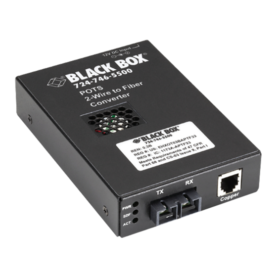
POTS 2-Wire to Fiber Converters
Connect your standard analog phone system
with fiber.
Connect central office voice signals to distant "Plain Old Telephone Service"
(POTS) equipment over fiber cables, using standard telephone signaling.
Order toll-free in the U.S.: Call 877-877-BBOX (outside U.S. call 724-746-5500)
Customer
FREE technical support 24 hours a day, 7 days a week: Call 724-746-5500 or fax
Support
724-746-0746 • Mailing address: Black Box Corporation, 1000 Park Drive, Lawrence,
Information
PA 15055-1018 • Web site: www.blackbox.com • E-mail: info@blackbox.com
TE160A-R2
TE161A-R2
TE162A-R2
BLACK BOX
TE163A-R2
TE164A-R2
TE165A-R2
®
Advertisement
Table of Contents

Related Manuals for Black Box TE160A-R2


Summary of Contents for Black Box TE160A-R2
- Page 1 Order toll-free in the U.S.: Call 877-877-BBOX (outside U.S. call 724-746-5500) Customer FREE technical support 24 hours a day, 7 days a week: Call 724-746-5500 or fax Support 724-746-0746 • Mailing address: Black Box Corporation, 1000 Park Drive, Lawrence, Information PA 15055-1018 • Web site: www.blackbox.com • E-mail: info@blackbox.com...
- Page 2 FCC and NOM Statements FEDERAL COMMUNICATIONS COMMISSION AND INDUSTRY CANADA RADIO FREQUENCY INTERFERENCE STATEMENTS This equipment generates, uses, and can radiate radio-frequency energy, and if not installed and used properly, that is, in strict accordance with the manufacturer’s instructions, may cause inter ference to radio communication. It has been tested and found to comply with the limits for a Class A computing device in accordance with the specifications in Subpart B of Part 15 of FCC rules, which are designed to provide reasonable protection against such interference...
- Page 3 NOM Statement 5. El aparato eléctrico no deberá ser usado cerca del agua—por ejemplo, cerca de la tina de baño, lavabo, sótano mojado o cerca de una alberca, etc. 6. El aparato eléctrico debe ser usado únicamente con carritos o pedestales que sean recomendados por el fabricante.
- Page 4 NOM Statement 17. Cuidado debe ser tomado de tal manera que objectos liquidos no sean derramados sobre la cubierta u orificios de ventilación. 18. Servicio por personal calificado deberá ser provisto cuando: A: El cable de poder o el contacto ha sido dañado; u B: Objectos han caído o líquido ha sido derramado dentro del aparato;...
- Page 5 Trademarks Used in this Manual Trademarks Used in this Manual Black Box and the Double Diamond logo are registered trademarks of BB Technologies, Inc. UL is a registered trademark of Underwriters Laboratories, Inc.. Any other trademarks mentioned in this manual are acknowledged to be the property of the trademark owners.
-
Page 6: Table Of Contents
4.3.1 Idle State (On-Hook) ............26 4.3.2 Telephone in Use (Off-Hook) ...........26 4.3.3 Central Office (CO) Rings the Telephone ......26 Troubleshooting ..................27 Problems/Solutions ...............27 Contacting Black Box ..............28 Shipping and Packaging ...............28 Appendix. Consumer Information ..............29 Page 6 724-746-5500 | blackbox.com... -
Page 7: Specifications
TE164A-R2–TE165A-R2: Single-mode: 16.0 dB RX Sensitivity — TE160A-R2–TE163A-R2: Multimode: -31.0 dBm; TE164A-R2–TE165A-R2: Single-mode: -30.0 dBm TX Power — TE160A-R2–TE163A-R2: Multimode: -19.0 dBm to -14.0 dBm, TE164A-R2–TE165A-R2: Single-mode: -15.0 dBm to -8.0 dBm CE Approval — Yes Connectors — TE160A-R2–TE161A-R2: (1) RJ-11, (1) pair of ST ®... -
Page 8: Fiber Cable
Bit Error Rate — Less than or equal to 10–9 Multimode Fiber (Recommended) — 62.5/125 µm Multimode Fiber (Optional) — 100/140, 85/140, 50/125 µm TE160A-R2–TE163A-R2: Cable — 1300-nm multimode fiber Fiber Optic Transmitter Power — Minimum: -19.0 dBm, Maximum: -14.0 dBm Fiber Optic Receiver Sensitivity —... - Page 9 Chapter 1: Specifications Ringing Supply — 90 Vp-p Ring Frequency — 15–30 Hz (reproduces the frequency detected by Unit A) Ring Cadence — Reproduces the cadence detected by Unit A Insertion Loss — 0.0 ± 1.0 dB at 1000 Hz (when both ports are teminated at 600 ohms) Page 9 724-746-5500 | blackbox.com...
-
Page 10: Overview
2.2 What’s Included Your package should include the following items. If anything is missing or damaged, contact Black Box Technical Support at 724-746-5500 or info@blackbox.com. • (1) POTS to 2-Wire Fiber Converter • Power supply •... -
Page 11: Hardware Description
2.3 Hardware Description Figures 2-1 through 2-6 show the side panels of the POTS 2-wire to fiber converter. Tables 2-2 through 2-7 describe their components. NOTE: TE160A-R2 and TE161A-R2 work together. Figure 2-1. Side panel (TE160A-R2). Table 2-2. Side-panel components (TE160A-R2). - Page 12 Chapter 2: Overview Figure 2-2. Side panel (TE161A-R2). Table 2-3. Side-panel components (TE161A-R2). Number Component Description Power LED Lights when power to the unit is on. SDF LED Lights when fiber link is connected. ACT LED Lights when active in use/ringing. (1) ST connector for TX Connect up to 1.2 mi.
- Page 13 Chapter 2: Overview NOTE: TE162A-R2 and TE163A-R2 work together. Figure 2-3. Side panel (TE162A-R2). Table 2-4. Side-panel components (TE162A-R2). Number Component Description Power LED Lights when power to the unit is on. SDF LED Lights when fiber link is connected. ACT LED Lights when active in use/ringing.
- Page 14 Chapter 2: Overview Figure 2-4. Side panel (TE163A-R2). Table 2-5. Side-panel components (TE163A-R2). Number Component Description Power LED Lights when power to the unit is on. SDF LED Lights when fiber link is connected. ACT LED Lights when active in use/ringing. (1) SC connector for TX Connect up to 1.2 mi.
- Page 15 Chapter 2: Overview NOTE: TE164A-R2 and TE165A-R2 work together. Figure 2-5. Side panel (TE164A-R2). Table 2-6. Side-panel components (TE164A-R2). Number Component Description Power LED Lights when power to the unit is on. SDF LED Lights when fiber link is connected. ACT LED Lights when active in use/ringing.
- Page 16 Chapter 2: Overview Figure 2-6. Side panel (TE165A-R2). Table 2-7. Side-panel components (TE165A-R2). Number Component Description Power LED Lights when power to the unit is on. SDF LED Lights when fiber link is connected. ACT LED Lights when active in use/ringing. (1) SC connector for TX Connect up to 12.4 mi.
-
Page 17: Typical Applications
One Unit A device and one Unit B device are required for the standard configuration. The Unit A device is connected to the Central Office (CO), and the Unit B device is connected to a telephone device. Unit B (TE161A-R2) Unit A (TE160A-R2) Emulates the Central Emulates the telephone Office (CO) device Figure 2-7. -
Page 18: Automatic Ring-Down Configuration
Chapter 2: Overview 2.4.2 Automatic Ring-Down Configuration Two Unit B devices are required for the ARD (automatic ring-down) configuration. ARD is a dedicated, point-to-point voice system. When one telephone is taken off- hook, the other telephone rings without dialing. Two Unit B devices, connected via the fiber ports, are required for this mode of operation, with a telephone device at each end. -
Page 19: Installation
Chapter 3: Installation 3. Installation CAUTION: Wear a grounding device and observe electrostatic discharge precautions when setting the jumpers. If you don’t, the device may not work. 3.1 Setting the Jumpers 1. Using a small screwdriver, remove the screws that secure the cover to the device and carefully remove the cover. -
Page 20: Us/Eu Telephone Regulation
3.1.2 US/EU Telephone Regulation The jumper labeled “US EU” is used to switch between the US or EU telephone configuration and is located on the top circuit board of Unit A (TE160A-R2, TE162A-R2, or TE164A-R2). This feature is required to comply with the EU TBR21 telephone regulation. The jumper has been set at the factory to the US setting as the default. -
Page 21: Installing The Cable-Standard Configuration
NOTE: Unit B MUST be configured for Standard Configuration (see Section 2.4.1). 3.3.1 Fiber 1. Use fiber cable with male, two-stranded TX to RX connectors installed at both ends. 2. Connect the fiber cables to Unit A (TE160A-R2, TE162A-R2, or TE164A-R2) as described: Page 21 724-746-5500 | blackbox.com... -
Page 22: Copper
• Connect the male TX cable connector to the female TX port. • Connect the male RX cable connector to the female RX port. Figure 3-5. Connecting the fiber cable to Unit A (TE160A-R2, TE162A-R2, or TE164A-R2) and Unit B (TE161A-R2, TE163A-R2, or TE165A-R2). -
Page 23: Installing The Cable-Automatic Ring-Down Configuration
Chapter 3: Installation 3. Connect the copper cables to Unit B (TE161A-R2, TE163A-R2, or TE165A-R2) as described: • Connect the RJ-11C connector at one end of the cable to the RJ-11C port on Unit B. • Connect the RJ-11C connector at the other end of the cable to the RJ-11C port on the telephone device. -
Page 24: Copper
Chapter 3: Installation 3. Connect the fiber cables to the second Unit B (TE161A-R2, TE163A-R2, or TE165A-R2) as described: • Connect the male TX cable connector to the female RX port. • Connect the male RX cable connector to the female TX port. 3.4.2 Copper 1. -
Page 25: Operation
For DC power, contact Black Box Technical Support at 724-746-5500 or info@blackbox.com. 4.2 Status LEDs Use the status LEDs to monitor the TE160A-R2–TE165A-R2 device operation in the network. PWR (Power) On = The device is connected to external power. -
Page 26: Loop-Start Operation
Chapter 4: Operation 4.3 Loop-Start Operation Loop-Start Service—commonly known as “Plain Old Telephone Service” (POTS)— is the primary analog signaling method used between telephone switches such as the Central Office (CO) and a telephone device. Loop-Start provides a way to indicate on-hook and off-hook conditions, which facilitates outgoing and incoming calls in a voice network. -
Page 27: Troubleshooting
• Is the power adapter properly installed in the device and in the outlet? • Does the external power source provide power? • Contact Black Box Technical Support at 724-746-5500 or info@blackbox.com. YES: • Proceed to Step 2. Step 2. Is the SDF (signal detect fiber link) LED lit? •... -
Page 28: Contacting Black Box
• Package it carefully. We recommend that you use the original container. • If you are returning the unit, make sure you include everything you received with it. Before you ship for return or repair, contact Black Box to get a Return Authorization (RA) number. -
Page 29: Appendix. Consumer Information
Appendix: Consumer Information Appendix. Consumer Information ACTA Compliance This equipment complies with Part 68 of the FCC rules and the requirements adopted by the Administrative Council for Terminal Attachments (ACTA). On the back of this equipment is a label that contains, among other information, a product identifier in the format US:AAAEQ##TXXXX. - Page 30 Repairs to the Equipment Aside from the jumper settings, the POTS 2-Wire to Fiber Converter is not intend- ed to be serviced by the user. If the equipment requires repair, contact Black Box Technical Support at 724-746-5500 or info@blackbox.com. Party Lines Connection to party line service is subject to state tariffs.
- Page 31 NOTES Page 31 724-746-5500 | blackbox.com...
- Page 32 724-746-5500 or blackbox.com. About Black Box Black Box Network Services is your source for an extensive range of networking and infrastructure products. You’ll find everything from cabinets and racks and power and surge protection products to media converters and Ethernet switches all supported by free, live 24/7 Tech support available in 30 seconds or less.
Need help?
Do you have a question about the TE160A-R2 and is the answer not in the manual?
Questions and answers