Advertisement
Quick Links
GS250 Gsense Multi-axis
Movement Detector V1.0
Installation Guide
Overview
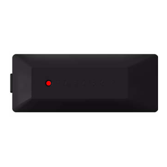
Figure 1: Front and rear views of the GS250.
A
C
B
D
E
Front View
Rear Exploded View
Table 1: The components of the GS250
Item
Name
A
Release clip
B
Status LED (movement, tamper, sensitivity programming)
C
Anti-tamper switch
D
Battery compartment
E
Battery pry slot
F
Mounting bracket
G
Anti-tamper pin
Printed in Canada | 05/2010
Installation
Screw Mounting
1.
Press the release clip and remove the mounting bracket from
GS250-EI00
the unit.
2.
Using the three mounting screws (provided), attach the
mounting plate to the protected object.
3.
Ensure that the battery is properly installed and clip the unit to
the mounting plate.
Tape Mounting
1.
Press the release clip and remove the mounting bracket from
the unit (see fig. 2).
Figure 2: Removing the mounting bracket.
2.
On the mounting bracket, break the four knock-outs and remove
anti-tamper pin. Remove excess plastic (see fig. 3).
F
Figure 3: Removing the anti-tamper pin.
G
3.
On the mounting tape, remove only the backing of the small
center rectangle. Stick the anti-tamper pin to the small rectangle
of mounting tape, and pull to separate it from the remaining
mounting tape.
Figure 4: Affixing the anti-tamper pin.
4.
Position the mounting bracket on the protected object and stick
the anti-tamper on the object. Ensure the correct orientation of
the anti-tamper pin (see fig. 5).
Figure 5: Ensuring the correct orientation when positioning device.
5.
Apply the remaining mounting tape to the mounting bracket
and stick the bracket to the protected object.
Figure 6: Affixing mounting bracket to the object.
LED Feedback
Table 2: LED feedback on the GS250
LED
Flash Sequence
Description
Red
On for 3 seconds
Alarm in normal mode
Red
Fast flash
Alarm in power saving mode
Test Mode
To enter test mode, simply insert the battery. If the battery is already
inserted, use a pen to press and release the anti-tamper switch. The
LED flashes red eight times quickly, signalling that the unit has
entered test mode. The LED's flash sequence is described in table 3.
Table 3: LED's flash sequence on the GS250
LED
Flash Sequence
Description
Red
3 x 8 fast flash
Power up
Amber 1 x flash per 5 seconds In test mode
Green 1 fast flash
Movement detected
Red
8 x fast flash
Tamper open
Red
8 x fast flash
Tamper closed
Red
8 x fast flash
Zone closed
Enough movement has occurred
Red
3 seconds On
to trigger an alarm
NOTE: The unit will exit test mode after 15 minutes, or after it has
been inactive for a period of five minutes.
Power Saving Mode
If two consecutive alarms occur within a five-minute period, the unit
goes into power saving mode for a period of three minutes. If a
movement is detected while in power saving mode, the LED emits
one red flash. No detection signals are transmitted to the panel.
GS250 Installation Guide | 1
Advertisement

Summary of Contents for Paradox GS250
- Page 1 Alarm in power saving mode Overview Test Mode Figure 1: Front and rear views of the GS250. To enter test mode, simply insert the battery. If the battery is already On the mounting bracket, break the four knock-outs and remove inserted, use a pen to press and release the anti-tamper switch.
-
Page 2: Specifications
Dimensions 7.5 x 2.7 x 0.64 cm (3 x 1.1 x 0.25 in.) Trademarks: Paradox is a trademark of Paradox Security Systems Ltd. or its affiliates in Canada, the United States and/or other countries. Certification: For the latest information on products approvals, such as UL and CE, please visit www.paradox.com.


Need help?
Do you have a question about the GS250 and is the answer not in the manual?
Questions and answers