
Subscribe to Our Youtube Channel
Related Manuals for Litecraft ILED-MP-07F5-010


Summary of Contents for Litecraft ILED-MP-07F5-010
- Page 1 LED Multipar 7FC ILED-MP-07F5-010 USER GUIDE PLEASE READ THESE INSTRUCTIONS CAREFULLY BEFORE USE...
-
Page 2: Table Of Contents
CONTENTS 1. Safety Instructions..................2 2. Technical Specifications................4 3. How to Set the Fixture ................. 5 3.1 Control Panel..................5 3.2 Main Function ..................6 4. How to Control the Unit ................11 4.1 Master/Slave Built In Preprogrammed Function........11 4.2. Easy Controller (by CA-8) ..............12 4.3 DMX Controller ..................12 5. -
Page 3: Safety Instructions
1. Safety Instructions Please read the instruction carefully, it includes important information about the installation, usage and maintenance. WARNING Please keep this User Guide for future consultation. If you sell the unit to another user, be sure that they also receive this instruction booklet. Please unpack and check carefully there is no transportation damage before using the unit. - Page 4 In the event of serious operating problem, stop using the unit immediately. Never try to repair the unit by yourself. Repairs carried out by unskilled people can lead to damage or malfunction. Please contact the nearest authorized technical assistance center. Always use the same type spare parts.
-
Page 5: Technical Specifications
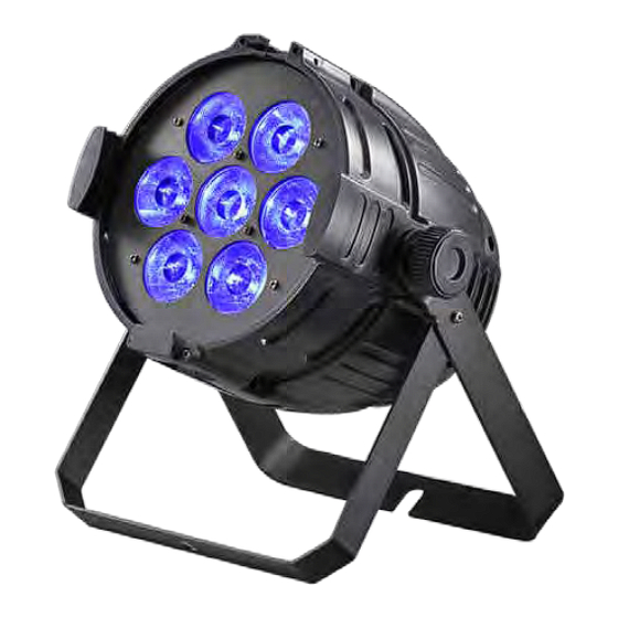
2. Technical Specifications ◇ Equipped with 7pcs of 10W Quad color LEDs, creating extra ordinary color mixing and powerful beam and wash effect ◇ DMX Channels: 4/5/7 channels selectable ◇ Beam Angle: 10° ◇ 0-100% full range dimmer and variable strobe speed ◇... -
Page 6: How To Set The Fixture
3. How to Set the Fixture 3.1 Control Panel 1. Mains Output: Connect to supply mains power for the unit. 2. DMX Output: For DMX512 link, use 3-pin XLR plug cable to link the next unit. 3. Mains Input: Connect to supply mains power for the unit. 4. -
Page 7: Main Function
Button: 11. MENU To select the programming functions 12. DOWN To go backward in the selected functions 13. UP To go forward in the selected functions 14. ENTER To confirm the selected functions 15. Only for remote control: Connect with CA-8 to control the unit for Stand by, Function and Mode function. - Page 9 DMX 512 Address Select the , press the ENTER button and the display will blink. Use the DOWN and UP button to change the DMX 512 address. Once the address has been selected, press the ENTER button to setup or automatically exit menu mode without any change after one minute. Back to the previous functions without any change press the MENU button.
- Page 10 (Dimmer 255); select the (Color 10), press the ENTER button, and select the (Red), (Green),… (Dimmer), pressing the ENTER button and adjust the brightness intensity from When you selected the (Fade mode), press the ENTER button, and then use the DOWN and UP button to adjust the fade speed from (Speed 1, the slowest) to (Speed 3: the fastest).
- Page 11 LED display Select the , press the ENTER button and the display will blink. Use the DOWN and UP button to select (LED display always on) or ( LED display off 20 seconds after exit menu) mode. Once select, press the ENTER button to setup or exit menu mode without any change after one minute.
-
Page 12: How To Control The Unit
Auto Test Select the , press the ENTER button and the unit will run the built-in programmer for self-test. To go back to the functions press the MENU button. Fixture Temperature Select the , press the ENTER button and the display will show the temperature of the unit. -
Page 13: Easy Controller (By Ca-8)
master automatically, set other units to slave 1 or slave 2 via menu, then the first unit will control the others to give an automatic, sound activated, synchronized light show. This function is good when you want an instant show. Any fixture can act as a Master or as a Slave. 2-light show In slave mode, slave 1 means the unit works as master, slave 2 means 2-light show. - Page 14 Please refer to the following diagram to address your DMX512 channel for the first 4 units:...
-
Page 15: Dmx 512 Configurations
5. DMX 512 Configurations 4/5/7 channels mode:... -
Page 16: Dmx 512 Connections
6. DMX 512 Connections 1. If you using a controller with 5 pins DMX output, you need to use a 5 to 3 pin adapter-cable. 2. At last unit, the DMX cable has to be terminated with a terminator. Solder a 120 ohm 1/4W resistor between pin 2(DMX-) and pin 3(DMX+) into a 3-pin XLR-plug and plug it in the DMX-output of the last unit. -
Page 17: Troubleshooting
5. Each lighting unit needs to have an address set to receive the data sent by the controller. The address number is between 0-511 (usually 0 & 1 are equal to 1). 6. The end of the DMX 512 system should be terminated to reduce signal errors. 7. -
Page 18: Fixture Cleaning
D. No response to the sound 1. Make sure the unit does not receive DMX signal. 2. Check microphone to see if it is good by tapping the microphone E. One of the channels is not working well 1. The stepper motor might be damaged or the cable connected to the PCB is broken. 2. - Page 19 Declaration of Conformity We declare that our products (lighting equipments) comply with the following specification and bears CE mark in accordance with the provision of the Electromagnetic Compatibility (EMC) Directive 89/336/EEC. EN55103-1: 2009 ; EN55103-2: 2009; EN62471: 2008; EN61000-3-2: 2006 + A1:2009 + A2:2009; EN61000-3-3: 2008. &...
- Page 20 Litecraft is continuously developing and improving all its products. We reserve the right to change specifications without prior notification. Images are representing but not necessarily a precise product reference. Litecraft shall be under no liability for any loss, damage or injury for direct or indirect dependence on the information contained in this guide.
Need help?
Do you have a question about the ILED-MP-07F5-010 and is the answer not in the manual?
Questions and answers