Advertisement
Quick Links
Advertisement

Subscribe to Our Youtube Channel
Related Manuals for Work Pro PA 9500 CDT Series


Summary of Contents for Work Pro PA 9500 CDT Series
- Page 1 PA 9500 CDT User Manual / Instrucciones de Usuario...
- Page 3 BEFORE OPERATING THIS AMPLIFIER, PLEASE CAREFULLY READING THIS OWNER'S MANUAL. SAFETY PRECAUTIONS: ¡The following symbols are used on this instrument. The lightning flash with arrowhead symbol, within an equilateral triangle, is intended to alert the user to the presence of uninsurable "dangerous voltage"...
-
Page 4: Table Of Contents
TABLE OF CONTENTS 1. Contents and features..........1 2. Caution...............2 3. Front Panel controls.............3 4. Rear Panel controls............4 5. Install and connections..........5 6. Operation..............8 7. Trouble shooting............11 8. Specifications............12 9. Example of possible connections.........14... -
Page 5: Caution
1. FEATURES AND GENERAL DESCRIPTION The CDT series have 90W output RMS, CD series with a compact disc player; CDT series with both of a compact disc player and digital tuner features. a. High quality design and construction. b. Full frequency response: 50Hz to 15,000 Hz at ¡3dB. c. - Page 6 HANDLE THE POWER CORD GENTLY. ¡To disconnect the plug from the AC outlet, pull on the plug itself, not on the cord. ¡Disconnect the plug from the AC outlet whenever the unit is to be left unused for an extended period of time. ¡...
-
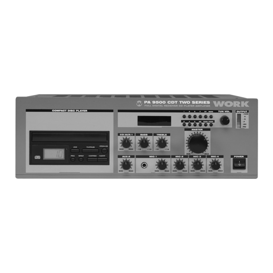
Page 7: Front Panel Controls
CLEANING. ¡ Remove dust by wiping the unit with a soft, dry cloth. If necessary, use a soft cloth lightly dampened with mild soapy water; then a dry cloth. Never use benzene, thinner alcohol or other volatile agents, and avoid spraying insecticides near the unit, other fluids with very strong vola- tility and flammability for cleaning the in it body. -
Page 8: Rear Panel Controls
8.MIC-1 PHONE JACK: Connects to a microphone of unbalanced low impedance (30-600 ohms). 9.AUX-1,AUX-2 VOLUME CONTROL: Adjusts gain of AUX-1, AUX-2 VOL. 10. COMPACT DISC PLAYER: DIGITAL display. 11. CD volume control: Adjust gain of CD vol. 12. CD power switch: Applies CD power. Two position buttons switch for on-off modes. -
Page 9: Install And Connections
5. INSTALL AND CONNECTIONS Caution: ¡ Before using this unit for the first time, be sure that the appliance's voltage is in accordance to your mains supply. Co- nnecting this unit only to grounded mains outlet. ¡ Re-apply the output terminal cover and fasten the screws after connected. - Page 10 BALANCED MICROPHONE INPUT CONNECTIONS: Using shielded cable, connect the two center conductors of the cable to prongs #2 and #3 of the A3M Microphone connector. Connect the shield of the cable to prong#1of the A3M Microphone connector. UNBALANCED MICROPHONE INPUT CONNECTIONS: Using shielded cable, connect the center conductor of the cable to prong #2 of the A3M Microphone connector.
- Page 11 PRIORITY PAGING: The amplifier features a transistorized circuit which automa- tically removes all program material for the amplifier and permits microphone #1 to take over for special or emergency announcements. This electronic switch is operated from the microphone, which must contain a single-pole switch, normally open for actuating this circuit.
-
Page 12: Operation
(2) The sum of the power capacities of the speakers must not exceed the output power capacity of the amplifier. (3) The length of the connecting cables must be short as poss- ible; in any case, the cables of long-distance must be covered in cross-section. - Page 13 b. Press the "UP" or "DOWN" button for a little time about 5 second, tuning will start automatically and stop at a broadcast station frequency with sufficient signal strength. (8) MANUAL TUNING. Auto tuning may be impossible if the broadcast signal is weak. If so, use manual tuning. a.
-
Page 14: Trouble Shooting
(13) Play the CD tape. When you press the CD power switch's button to on, then the compact disc player will display, at the same time, tell you that the CD player at the state of ready work. a. Press the open/close button, the CD window will push out, then take a CD tape in it. - Page 15 IF THE PROBLEM IS --- MAKE SURE THAT THE --- No lights illuminate when Unit is plugged into a live outlet, POWER button is pressed. was the AC fuse opened The fan no work. unit is plugged into a live outlet, was the AC fuse opened No sound is heard.
-
Page 16: Specifications
8. Specifications Type Mixer power amplifier Model 90W series with CD/CDT Power output Rated: 90W max: 120W Output regulation Less than 2dB no load to full load Outputs Speaker output (balanced) 4£ (18.9V), 8£ (26.8V), 16£ (37.9V), 70V(54.4£),100V(111£) 120W 4£ (21.9V), 8£ (30.9V), 16£ (43.8V), 70V (42£),100V (83£) RECV: 4.7K Ohms, 650mV SEND: 600ohms, 1V... - Page 17 Controls INPUT 1 volume control Tone controls (BASS, TREBLE) INPUT 2 volume control CD volume control AUX-1 volume control INPUT 3 volume control MASTER volume control INPUT 4 volume control TUNER volume control AUX-2 volume control Indicator Power indicator (LED) LED output level meter AC power supply see rear panel's marked*...
-
Page 18: Example Of Possible Connections
9. Example of possible connections 100V 100V 100V ANTENNA 75£ OUT PUT DC SW. 4£ 8£ 16£ 70V 100V RATED SUPPLY VOLTAGE: 230V~50Hz CAUTION RISK OF ELECTRIC SHOCK. DO NOT OPEN. CAUTION : TO REDUCE THE RISK OF FIRE OR ELECTRIC SHOCK, DO NOT REMOVE THE COVER (OR BACK ) OR EXPOSE THIS PRODUCT TO RAIN OR MOISTURE. - Page 19 ¡Use this unit with pre-ampfilier. ANTENNA 75£ OUT PUT DC SW. 4£ 8£ 16£ 70V 100V RATED SUPPLY VOLTAGE: 230V~50Hz CAUTION RISK OF ELECTRIC SHOCK. DO NOT OPEN. CAUTION : TO REDUCE THE RISK OF FIRE OR ELECTRIC SHOCK, DO NOT REMOVE THE COVER (OR BACK ) OR EXPOSE THIS PRODUCT TO RAIN OR MOISTURE.
- Page 20 Equipson, S.A. www.equipson.es support@equipson.es...
Need help?
Do you have a question about the PA 9500 CDT Series and is the answer not in the manual?
Questions and answers
Esquema gráfico