
Subscribe to Our Youtube Channel
Related Manuals for Kleenmaid FEG905X

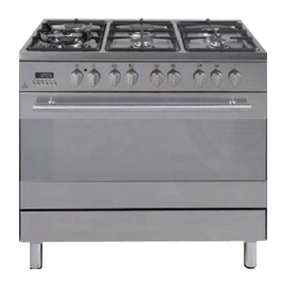
Summary of Contents for Kleenmaid FEG905X
- Page 1 FEG905X - 900mm Stainless Steel Freestanding Range Gas Cooktop, Electric Multi Function Oven...
-
Page 2: Product Label
Kleenmaid appliance. This appliance has been designed and manufactured to give you years of reliable performance. For best results, carefully read the instructions on how to install your new appliance. Correct installation will avoid delays and unnecessary service calls. - Page 3 FIRST TIME USE THE OVEN It is advised to follow these instructions: Clean the interior of the oven with cloth soaked in water and detergent (neutral) then dry carefully. Fit the wire racks as described at chapter “Use and care”. Insert shelves and tray.
-
Page 4: Important Precautions And Recommendations
IMPORTANT PRECAUTIONS AND RECOMMENDATIONS After having unpacked the appliance, check to ensure that it is not damaged. In case of doubt, do not use it and consult your supplier or a professionally qualified techni- cian. Packing elements (i.e. plastic bags, polystyrene foam, nails, packing straps, etc.) should not be left around within easy reach of children, as these may cause serious injuries. -
Page 5: Installation
INSTALLATION CAUTION: This appliance must be installed in accordance with these installation instructions. This appliance shall only be serviced by authorized personnel. This appliance is to be installed only by an authorised person. Incorrect installation, for which the manufacturer accepts no responsibility, may cause personal injury of damage. - Page 6 CLEARANCES Installation clearances and protection of combustible surfaces shall comply with the current local regulations eg. AG 601 (AS 5601) Gas Installations code. Installation shall comply with the dimension in Fig 1 bearing in mind that Overhead Clearances In no case shall the clearances between the highest part of the cooker be less than 650mm for an overhead exhaust fan.
-
Page 7: Fitting The Adjustable Feet
FITTING THE ADJUSTABLE FEET The adjustable feet must be fitted to the base of the cooker before use. Rest the rear of the cooker an a piece of the polystyrene packaging exposing the base for the fitting of the feet. Fit the 4 legs by screwing them tight into the support base as shown in figure 3. -
Page 8: Moving The Cooker
MOVING THE COOKER WARNING When raising cooker to upright position always ensure two people carry out this manoeuvre to prevent damage to the adjustable feet (fig. 5). Figure 5 WARNING WARNING Be careful: do not lift the cooker When moving cooker to its final posi- by the door handle when raising tion DO NOT DRAG (fig. -
Page 9: Anti-Tilt Bracket
ANTI-TILT BRACKET Fixing the anti-tilt bracket: After you have located where the cooker is to be positioned mark, on the wall, the place where the 2 screws of the anti-tilt bracket have to be fitted. Please fol- low the indications given in the drawing below. Make two holes of diameter 8mm diameter on the wall and insert the plastic plugs. -
Page 10: Gas Supply
GAS SUPPLY: The connection must be executed by an authorised person according to the rele- vant standards. Before connecting the appliance to the gas main, mount the brass conical adaptor onto the gas inlet pipe, upon which the gasket has been placed (figures 9-10). Conical adaptor and gasket are supplied with the appliance (packed with conver- sion kit for use with Natural gas or Propane gas). - Page 11 1. After connecting the gas supply, check the piping and connections for leaks using a soap and water solution. The presence of bubbles indicates a leak, tighten or replace connections as appropriate. Warning: Do not use any naked flame to check for leaks. 2.
- Page 12 CONVERSION PROCEDURE (to convert to Propane gas) REPLACING THE INJECTORS This appliance is suitable for use with Natural gas or Propane gas (check the “gas type” sticker attached to the appliance). A label stating the type of gas used after replacing the injectors must be attached at the rear of the appliance, in proximity of the gas inlet connection.
- Page 13 MINIMUM BURNER SETTING ADJUSTMENT Check whether the flame spreads to all burner ports when the burner is lit with the gas tap set to the minimum position. If some ports do not light, increase the minimum gas rate setting. Check whether the burner remains lit even when the gas tap is turned quickly from the maximum to the minimum position.
-
Page 14: Lubrication Of The Gas Taps
TABLE FOR THE CHOICE OF THE INJECTORS Natural gas Propane gas 2.75 Test Point Pressure [kPa] Injector Injector Orifice Dia. Consumption Orifice Dia. Consumption BURNER [mm] [MJ/h] [mm] [MJ/h] 0.85 3.60 0.53 3.60 Auxiliary (A) 1.12 6.30 0.70 6.30 Semi-rapid (SR) 1.45 10.30 0.91... -
Page 15: Using The Oven For The First Time
USE and CARE CAUTION: This appliance must be used only for the task it has explicitly been designed for, that is for domestic cooking of foodstuffs. Any other form of usage is to be con- sidered as inappropriate and therefore dangerous. Do NOT place combustible materials or products on this appliance at any time. -
Page 16: Grease Filter
GREASE FILTER A special screen is provided at the back of the oven to catch grease particles, mainly when meat is being roasted (fig. 18). When backing pastry etc. this filter should be removed. Always clean the filter after cooking as any solid residues on it might adversely affect the oven performance. -
Page 17: Gas Burners
GAS HOB Figure 20 GAS BURNERS Natural Gas Propane gas MJ/h MJ/h 1. Triple ring burner (TC) 13.0 11.9 2. Semi-rapid burner (SR) 3. Rapid burner (R) 10.3 10.8 4. Semi-rapid burner (SR) 5. Auxiliary burner (A) 6. Auxiliary burner (A) - Page 18 LIGHTING GAS BURNERS FITTED WITH SAFETY VALVE DEVICE AND ELECTRONIC IGNITION Figure 21 Check that the electricity is switched on to allow spark igni- tion. Make sure that all controls are turned to zero. The gas flow to the burners is controlled by taps with a safety cutout device.
- Page 19 CHOICE OF BURNER The burner must be chosen according to the diameter of the pans and energy required. For optimum efficiency use a wok or pan no smaller than 230 mm diameter. Figure 22 Burners Pan diameter Auxiliary 12 - 14 cm Semi-rapid 16 - 24 cm Rapid...
- Page 20 CORRECT USE OF TRIPLE-RING BURNER The flat-bottomed pans are to be placed directly onto the pan-support. To use the WOK, you must place the wok stand in the CORRECT position as shown in Fig. 24a-24b. Figure 24a Figure 24b WRONG CORRECT Figure 25 GRATE FOR SMALL PANS...
-
Page 21: Control Panel
CONTROL PANEL Figure 26 CONTROL PANEL - Controls description 1. Electronic programmer 2. Multifunction oven switch knob 3. Multifunction oven thermostat knob 4. Front left burner control knob 5. Rear left burner control knob 6. Front central burner control knob 7. -
Page 22: Operating Principles
OPERATING PRINCIPLES Heating and cooking in the MULTI-FUNCTION oven are obtained in the following ways: a. by normal convection The heat is produced by the upper and lower heating elements. b. by forced convection The fan draws in air contained within the oven housing at the rear of the oven and forces it over the circular heating element. -
Page 23: Oven Light
OVEN LIGHT By setting the knob to this position, only the oven light comes on (15 W). It remains on in all the cooking modes. TRADITIONAL BAKE The upper and lower heating elements come on. The heat being dispersed by natural convection. -
Page 24: Fan Grill
FAN FORCED The circular element and fan come on. The heat is dispersed by forced convection and the temperature can be varied to between 50° and 225°C via the thermostat knob. The oven does not require preheating. Ideal for: Food which has to be well-cooked outside and soft or rosy inside, for example lasagne, lamb, roast beef, whole fish etc. -
Page 25: Cooking Advice
COOKING ADVICE STERILIZATION Sterilization of foods to be conserved, in full and hermetically sealed jars, is done in the following way: a. Set the switch to position b. Set the thermostat knob to position 185 °C and preheat the oven. c. -
Page 26: Use Of The Grill
GRILLING AND “AU GRATIN” As the hot air completely covers the food to be cooked, grilling may be done with the food on rack in the oven. The knob should be switched to position The thermostat should be set to 175 °C and the oven pre-heated. The food should be placed on a rack in the oven for the required cooking time. - Page 27 ROTISSERIE Figure 28 (Fig. 29) This is used for spit roasting under the grill and comprises: an electric motor fitted to the rear of the oven a stainless steel skewer provided with slide-out heatless handgrip and two sets of adjustable forks a skewer support to be fitted in the middle runner.
- Page 28 RECOMMENDED COOKING TEMPERATURE Food °C °F Shelf Cooking Mark Position Time (approx) CAKES Victoria sandwich 2 or 3 20-25 mins Small cakes/buns 1 and 2 15-20 mins Madeira cake 2 or 3 20 mins 3 /4 Fruit cake hours 1 /2 Rich fruit cake 3 or 4 hours...
-
Page 29: Electronic Programmer
ELECTRONIC PROGRAMMER The electronic programmer is a device which groups together the following functions: 24 hours clock with illuminated display Timer (up to 23 hours and 59 minutes) Program for automatic oven cooking Program for semi-automatic oven cooking Description of the buttons: Timer Cooking time End of cooking time... -
Page 30: Electronic Clock
ELECTRONIC CLOCK (fig. 31) The illuminated figures on the clock represent hours and minutes on 24 hour clock. When first connected, or after a power failure, three zeros will flash on the display. To set the time press the button and then the Please note that changing the hour button deletes any cooking program. -
Page 31: Electronic Timer
ELECTRONIC TIMER The timer program consists only of a buzzer which may be set for a maximum period of 23 hours and 59 minutes. If AUTO is flashing on the panel, push the button. To set the time, push the button and the until you obtain the desired time in the panel (fig. -
Page 32: Automatic Oven Cooking
AUTOMATIC OVEN COOKING To cook food automatically in the oven, it is necessary to: 1.Set the length of the cooking time 2.Set the end of the cooking time 3.Set the temperature and the oven cooking program. These operations are performed as follows: 1.Set the length of the cooking time by pushing the button and the button to... -
Page 33: Semi - Automatic Cooking
SEMI - AUTOMATIC COOKING This function is only used to set the END of the cooking time of the oven. There are two ways of setting this function. 1. Set the length of the cooking time by pushing the button and the button to advance, or to go backwards (Fig. -
Page 34: Cleaning And Maintenance
Cleaning and Maintenance Maintenance Description Period Daily • Clean gas cooktop as per instructions below • Remove burner caps, burner rings & base and clean using non abrasive detergent & rinse in cold water & dry thoroughly Monthly before replacing back on hob •... -
Page 35: Replacing The Oven Light Bulb
OVEN The oven with smooth enamel must be cleaned after every use, using suitable prod- ucts. Please note that after using the oven for 30 minutes on the highest temperature eliminates most grime reducing it to ashes. Do not use abrasive substances to clean the oven. INSIDE OF OVEN This must be cleaned regularly. - Page 36 GAS TAPS CORRECT REPLACEMENT OF THE BURNERS If the gas taps are not working proper- ly, call our Customer Service Centre to It is essential to check that the burner obtain the nearest Authorized Service flame distributor F and the cap C has Agent.
- Page 37 TRIPLE RING BURNER The triple burner must be correctly positioned (see fig. 42); the burner rib must be fit- ted squarely as shown by the arrow (see fig. 40). Then position the cap A and the ring B (fig. 41 - 42). The burner correctly positioned must not rotate (fig.
-
Page 38: Storage Compartment
REMOVAL OF THE INNER GLASS DOOR PANEL The inner glass door panel can easily be removed for cleaning by unscrewing the four screws (fig. 43). When re-assembly ensure that the inner glass is correctly positioned and do not over tighten the screws. Figure 43 STORAGE COMPARTMENT The storage compartment is accessible through the pivoting panel. - Page 39 GRILL HEATING ELEMENT The heating element is self-cleaning and does not require maintenance. OVEN TRAY Figure 45 The oven tray must be correctly plac- ing on its wire shelf support (fig. 45) then insert into the side runners (fig. Figure 46...
-
Page 40: Dismantling The Door
Figure 47a DISMANTLING THE DOOR Please operate as follows: Open the door completely. The swivel retainers of the rh and lh hinges (fig. 47a) are hooked onto the metal bar above them (fig. 47b). Lift the oven door slightly. The notch on the bottom of the hinge will disengage (fig. - Page 41 Service and Maintenance If the ignition spark fails to ignite or does not light the gas, check the following items before calling our Customer Service Centre to obtain the nearest Authorised Service Agent: Burner is reassembled and located correctly. Spark electrode and white ceramic are clean and dry. 240 VAC power supply is connected.
-
Page 42: Wiring Diagram
WIRING DIAGRAM 1131481 Oven switch diagram ELECTRIC DIAGRAM KEY 10 11 POSITION Oven switch Oven thermostat 40° FUNCTION Oven lamp Oven light Rotisserie switch FUNCTION 80° Rotisserie Traditional convection cooking Cooling fan FUNCTION 120° Oven programmer Grilling Top element FUNCTION 160°... - Page 43 Kleenmaid appliance, we guarantee that any fault caused by faulty material or workmanship becoming apparent, will be rectified free of charge for parts and labour, provided that all service is performed during normal working hours by Kleenmaid or their designated Agents.
Need help?
Do you have a question about the FEG905X and is the answer not in the manual?
Questions and answers