Table of Contents
Advertisement
Quick Links
This service information is designed for experienced repair technicians only and is not designed for use by the general public.
It does not contain warnings or cautions to advise non-technical individuals of potential dangers in attempting to service a product.
Products powered by electricity should be serviced or repaired only by experienced professional technicians. Any attempt to service
or repair the products dealt with in this service information by anyone else could result in serious injury or death.
In order to avoid frostbite, be assured of no refrigerant leakage during the installation or repairing of refrigerant circuit.
WARNING
PRECAUTION OF LOW TEMPERATURE
Indoor Unit
CS-E9PKEA
CS-E12PKEA
CS-E15PKEA
CS-E18PKEA
Order No: PAPAMY1212049CE
Outdoor Unit
CU-E9PKEA
CU-E12PKEA
CU-E15PKEA
CU-E18PKEA
Destination
Europe
© Panasonic Corporation 2012.
Advertisement
Table of Contents

Related Manuals for Panasonic CS-E9PKEA


Summary of Contents for Panasonic CS-E9PKEA
- Page 1 PRECAUTION OF LOW TEMPERATURE In order to avoid frostbite, be assured of no refrigerant leakage during the installation or repairing of refrigerant circuit. © Panasonic Corporation 2012.
-
Page 2: Table Of Contents
Indoor Unit ..........15 15.4 Self-diagnosis Method....... 61 Outdoor Unit ..........15 Remote Control ..........15 16. Disassembly and Assembly Instructions ..89 16.1 CS-E9PKEA CS-E12PKEA CS-E15PKEA... 5. Dimensions ............16 ..............89 Indoor Unit ..........16 16.2 CS-E18PKEA ..........94 Outdoor Unit ..........18 16.3 Outdoor Electronic Controller Removal Procedure .......... -
Page 3: Safety Precautions
1. Safety Precautions • Read the following “SAFETY PRECAUTIONS” carefully before perform any servicing. • Electrical work must be installed or serviced by a licensed electrician. Be sure to use the correct rating of the power plug and main circuit for the model installed. •... - Page 4 WARNING During pump down operation, stop the compressor before remove the refrigeration piping. (Removal of compressor while compressor is operating and valves are opened will cause suck-in of air, abnormal high pressure in refrigeration cycle and result in explosion, injury etc.) After completion of installation or service, confirm there is no leakage or refrigerant gas.
-
Page 5: Specifications
2. Specifications Indoor CS-E9PKEA Model Outdoor CU-E9PKEA Performance Test Condition EUROVENT Phase, Hz Single, 50 Power Supply Min. Mid. Max. 0.85 2.50 3.00 Capacity BTU/h 2900 8530 10200 Kcal/h 2150 2580 Running Current – 2.40 – Input Power Annual Consumption –... - Page 6 Indoor CS-E9PKEA Model Outdoor CU-E9PKEA Type Hermetic Motor (Rotary) Compressor Motor Type Brushless (4 poles) Output Power Type Cross-Flow Fan Material ASG33 Motor Type DC / Transistor (8-poles) Input Power 44.9 Output Power Cool Heat Cool Heat Cool Speed Heat...
- Page 7 Indoor CS-E9PKEA Model Outdoor CU-E9PKEA Pipe Diameter (Liquid / Gas) mm (inch) 6.35 (1/4) / 9.52 (3/8) Standard length m (ft) 5.0 (16.4) Length range (min – max) m (ft) 3 (9.8) ~ 15 (49.2) I/D & O/D Height different m (ft) 5.0 (16.4)
- Page 8 Indoor CS-E12PKEA CS-E15PKEA Model Outdoor CU-E12PKEA CU-E15PKEA Performance Test Condition EUROVENT EUROVENT Phase, Hz Single, 50 Single, 50 Power Supply Min. Mid. Max. Min. Mid. Max. 0.85 3.50 4.00 0.98 4.20 5.00 Capacity BTU/h 2900 11900 13600 3340 14300 17100 Kcal/h 3010 3440...
- Page 9 Indoor CS-E12PKEA CS-E15PKEA Model Outdoor CU-E12PKEA CU-E15PKEA Type Hermetic Motor (Rotary) Hermetic Motor (Rotary) Compressor Motor Type Brushless (4 poles) Brushless (4 poles) Output Power Type Cross-Flow Fan Cross-Flow Fan Material ASG33 ASG33 Motor Type DC / Transistor (8-poles) DC / Transistor (8-poles) Input Power 44.9 44.9...
- Page 10 Indoor CS-E12PKEA CS-E15PKEA Model Outdoor CU-E12PKEA CU-E15PKEA Pipe Diameter (Liquid / Gas) mm (inch) 6.35 (1/4) / 9.52 (3/8) 6.35 (1/4) / 12.70 (1/2) Standard length m (ft) 5.0 (16.4) 5.0 (16.4) Length range (min – max) m (ft) 3 (9.8) ~ 15 (49.2) 3 (9.8) ~ 15 (49.2) I/D &...
- Page 11 Indoor CS-E18PKEA Model Outdoor CU-E18PKEA Performance Test Condition EUROVENT Phase, Hz Single, 50 Power Supply Min. Mid. Max. 0.98 5.00 6.00 Capacity BTU/h 3340 17100 20500 Kcal/h 4300 5160 Running Current – – Input Power 1.44k 1.99k Annual Consumption – –...
- Page 12 Indoor CS-E18PKEA Model Outdoor CU-E18PKEA Type Hermetic Motor (Rotary) Compressor Motor Type Brushless (4 poles) Output Power Type Cross-Flow Fan Material ASG33 Motor Type DC / Transistor (8-poles) Input Power 94.8 Output Power Cool Heat Cool Heat Cool 1010 Speed Heat 1070 Cool...
- Page 13 Indoor CS-E18PKEA Model Outdoor CU-E18PKEA Pipe Diameter (Liquid / Gas) mm (inch) 6.35 (1/4) / 12.70 (1/2) Standard length m (ft) 5.0 (16.4) Length range (min – max) m (ft) 3 (9.8) ~ 20 (65.6) I/D & O/D Height different m (ft) 15.0 (49.2) Additional Gas Amount...
-
Page 14: Features
Features • Inverter Technology Wider output power range Energy saving Quick Cooling Quick Heating More precise temperature control • Environment Protection Non-ozone depletion substances refrigerant (R410A) • Long Installation Piping Long piping up to 15 meters (0.75 ~ 1.75HP) and 20 meters (2.0 ~ 2.25HP) •... -
Page 15: Location Of Controls And Components
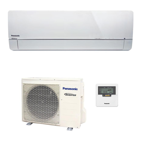
4. Location of Controls and Components Indoor Unit Outdoor Unit Remote Control... -
Page 16: Dimensions
5. Dimensions Indoor Unit 5.1.1 CS-E9PKEA CS-E12PKEA CS-E15PKEA... - Page 17 5.1.2 CS-E18PKEA...
-
Page 18: Outdoor Unit
Outdoor Unit 5.2.1 CU-E9PKEA CU-E12PKEA 5.2.2 CU-E15PKEA CU-E18PKEA... -
Page 19: Refrigeration Cycle Diagram
6. Refrigeration Cycle Diagram CU-E9PKEA CU-E12PKEA INDOOR OUTDOOR LIQUID EXPANSION SIDE VALVE MUFFLER STRAINER 2-WAY VALVE INTAKE TEMP. PIPE SENSOR TEMP. CONDENSER SENSOR HEAT EXCHANGER (EVAPORATOR) SIDE 4-WAYS VALVE 3-WAY MUFFLER VALVE COMPRESSOR COOLING HEATING... -
Page 20: Cu-E15Pkea Cu-E18Pkea
CU-E15PKEA CU-E18PKEA INDOOR OUTDOOR LIQUID EXPANSION SIDE VALVE STRAINER 2-WAY PROCESS VALVE TUBE TEMP. SENSOR CONDENSER INTAKE TEMP. PIPE SENSOR TEMP. SENSOR PIPE TEMP. SENSOR HEAT EXCHANGER DIS. TEMP. (EVAPORATOR) SENSOR SIDE 4-WAYS VALVE 3-WAY VALVE TANK SENSOR COMPRESSOR COOLING HEATING... -
Page 21: Block Diagram
7. Block Diagram CS-E9PKEA CU-E9PKEA CS-E12PKEA CU-E12PKEA... -
Page 22: Cs-E15Pkea Cu-E15Pkea Cs-E18Pkea Cu-E18Pkea
CS-E15PKEA CU-E15PKEA CS-E18PKEA CU-E18PKEA... -
Page 23: Wiring Connection Diagram
8. Wiring Connection Diagram Indoor Unit GROUNDING TERMINAL ELECTRONIC CONTROLLER (MAIN) TERMINAL BOARD RY-PWR CN-CNT (WHT) RY-PWR2 FUSE301 T3.15A L250V AC304 (RED) AC303 TEMP. (WHT) FUSE UP DOWN NOISE CN-STM1 102°C (3A) G301 LOUVER MOTOR FILTER (WHT) TEMP. (OUTER) (GRN) OUTDOOR CIRCUIT FUSE... -
Page 24: Outdoor Unit
Outdoor Unit 8.2.1 CU-E9PKEA CU-E12PKEA Resistance of Compressor Windings MODEL CU-E9PKEA / CU-E12PKEA CONNECTION 5RD102XBE21 (Ω) 1.897 1.907 1.882 Note: Resistance at 20°C of ambient temperature. - Page 25 8.2.2 CU-E15PKEA CU-E18PKEA Resistance of Compressor Windings MODEL CU-E15PKEA / CU-E18PKEA CONNECTION 5RD132XBA21 (Ω) 1.897 1.907 1.882 Note: Resistance at 20°C of ambient temperature.
-
Page 26: Electronic Circuit Diagram
9. Electronic Circuit Diagram Indoor Unit... -
Page 27: Outdoor Unit
Outdoor Unit 9.2.1 CU-E9PKEA CU-E12PKEA TO INDOOR UNIT REACTOR TERMINAL (BLACK) (WHITE) (RED) BOARD RAT2 RAT1 (GRY) (GRY) *CN-STM *C174 *D73 EXPANSION *D74 VALVE ELECTRONIC *D75 *D76 CONTROLLER 15.8k 15.0k 220µ 1µ 1µ OUTDOOR AIR TEMP. DATA SENSOR (15kΩ 3950) (RED) NOISE FILTER... - Page 28 9.2.2 CU-E15PKEA CU-E18PKEA TO INDOOR UNIT REACTOR TERMINAL (BLK) (WHT) (RED) BOARD L2-I L2-O (GRAY) (GRAY) COMP. TEMP. SENSOR R410 1µ 4.99k (THERMISTOR) COM3 (RED) (50kΩ 3950) COMMUNICATION OUTDOOR AIR TEMP. CIRCUIT SENSOR R101 R100 (THERMISTOR) 15.8k 15.0k AC-BLK (15kΩ 3950) (BLACK) FUSE3 1µ...
-
Page 29: Printed Circuit Board
10. Printed Circuit Board 10.1 Indoor Unit 10.1.1 Main Printed Circuit Board 10.1.2 Indicator Printed Circuit Board... -
Page 30: Outdoor Unit
10.2 Outdoor Unit 10.2.1 CU-E9PKEA CU-E12PKEA... - Page 31 10.2.2 CU-E15PKEA CU-E18PKEA...
-
Page 32: Installation Instruction
11. Installation Instruction 11.1 Select the Best Location 11.1.3 Indoor/Outdoor Unit Installation Diagram 11.1.1 Indoor Unit • Do not install the unit in excessive oil fume area such as kitchen, workshop and etc. • There should not be any heat source or steam near the unit. -
Page 33: Indoor Unit
11.2 Indoor Unit The mounting wall shall be strong and solid enough to prevent it from vibration. Dimension Model E9****, E12****, E15**** 490 mm 82 mm 439 mm 432 mm 43 mm 95 mm E18**** 590 mm 82 mm 539 mm 532 mm 169 mm 219 mm... - Page 34 11.2.2 Indoor Unit Installation 11.2.2.1 For the right rear piping 11.2.2.2 For the right and right bottom piping 11.2.2.3 For the embedded piping (This can be used for left rear piping and bottom piping also.)
-
Page 35: Connect The Cable To The Indoor Unit
11.2.3 Connect the Cable to the Indoor Unit The power supply cord, indoor and outdoor unit connection cable can be connected without removing the front grille. Install the indoor unit on the installing holder that mounted on the wall. Open the front panel and grille door by loosening the screw. Cable connection to the power supply through Isolating Devices (Disconnecting means). - Page 36 Remove the tapes and connect the power supply cord and connection cable between indoor unit and outdoor unit according to the diagram below. Secure the power supply cord and connection cable onto the control board with the holder. Close grille door by tighten with screw and close the front panel. Note: •...
- Page 37 11.2.3.2 Cutting and flaring the piping Please cut using pipe cutter and then remove the burrs. Remove the burrs by using reamer. If burrs are not removed, gas leakage may be caused. Turn the piping end down to avoid the metal powder entering the pipe. Please make flare after inserting the flare nut onto the copper pipes.
-
Page 38: Outdoor Unit
11.3 Outdoor Unit 11.3.1 Install the Outdoor Unit • After selecting the best location, start installation according to Indoor/Outdoor Unit Installation Diagram. Fix the unit on concrete or rigid frame firmly and horizontally by bolt nut (ø10 mm). When installing at roof, please consider strong wind and earthquake. Please fasten the installation stand firmly with bolt or nails. -
Page 39: Evacuation Of The Equipment
11.3.3 Evacuation of the Equipment WHEN INSTALLING AN AIR CONDITIONER, BE SURE TO EVACUATE THE AIR INSIDE THE INDOOR UNIT AND PIPES in the following procedure. Connect a charging hose with a push pin to the Low side of a charging set and the service port of the 3-way valve. -
Page 40: Connect The Cable To The Outdoor Unit
11.3.4 Connect the cable to the Outdoor Unit Remove the control board cover from the unit by loosening the screw. Connection cable between indoor unit and outdoor unit shall be approved polychloroprene sheathed 4 × 1.5 (1.0 ~ 1.75HP) or 4 × 2.5 mm (2.0HP) flexible cord, type designation 60245 IEC 57 or heavier cord. -
Page 41: Operation Control
12. Operation Control 12.1 Basic Function Inverter control, which equipped with a microcomputer in determining the most suitable operating mode as time passes, automatically adjusts output power for maximum comfort always. In order to achieve the suitable operating mode, the microcomputer maintains the set temperature by measuring the temperature of the environment and performing temperature shifting. -
Page 42: Indoor Fan Motor Operation
12.1.5 Automatic Operation • This mode can be set using remote control and the operation is decided by remote control setting temperature, remote control operation mode and indoor intake air temperature. • During operation mode judgment, indoor fan motor (with speed of Lo-) is running for 30 seconds to detect the indoor intake air temperature. -
Page 43: Outdoor Fan Motor Operation
[Heating] • According to indoor pipe temperature, automatic heating fan speed is determined as follows. B. Feedback control • Immediately after the fan motor started, feedback control is performed once every second. • During fan motor on, if fan motor feedback ≥ 2550 rpm or < 50 rpm continue for 10 seconds, then fan motor error counter increase, fan motor is then stop and restart. -
Page 44: Airflow Direction
Control of airflow direction can be automatic (angles of direction is determined by operation mode, heat exchanger temperature and intake air temperature) and manual (angles of direction can be adjusted using remote control). 12.4.1 Vertical Airflow CS-E9PKEA CS-E12PKEA CS-E15PKEA Upper Vane Angle (°) Lower Vane Angle (°) Operation Mode Airflow Direction... -
Page 45: Quiet Operation (Cooling Mode/Cooling Area Of Dry Mode)
12.4.2 Horizontal Airflow • Automatic horizontal airflow direction can be set using remote control; the vane swings left and right within the angles as stated below. For heating mode operation, the angle of the vane depends on the indoor heat exchanger temperature as Figure 1 below. -
Page 46: Quiet Operation (Heating)
12.6 Quiet operation (Heating) • Purpose To provide quiet heating operation compare to normal operation. • Control condition Quiet operation start condition When “POWERFUL/QUIET” button at remote control is pressed. POWERFUL/QUIET LED illuminates. Quiet operation stop condition When one of the following conditions is satisfied, quiet operation stops: •... -
Page 47: Timer Control
12.8 Timer Control • To turn ON or OFF the unit at a preset time. 12.8.1 ON Timer Control... -
Page 49: Auto Restart Control
12.9 Auto Restart Control • When the power supply is cut off during the operation of air conditioner, the compressor will re-operate within three to four minutes (there are 10 patterns between 2 minutes 58 seconds and 3 minutes 52 seconds to be selected randomly) after power supply resumes. -
Page 50: Protection Control
13. Protection Control 13.1 Protection Control For All Operations 13.1.1 Restart Control (Time Delay Safety Control) • The Compressor will not turn on within 3 minutes from the moment operation stops, although the unit is turned on again by pressing OFF/ON button at remote control within this period. •... - Page 51 13.1.4 Compressor Overheating Prevention Control • Instructed frequency for compressor operation will be regulated by compressor discharge temperature. The changes of frequency are as below. • If compressor discharge temperature exceeds 107°C, compressor will be stopped, occurs 4 times per 20 minutes, timer LED will be blinking.
-
Page 52: Protection Control For Cooling & Soft Dry Operation
13.2 Protection Control For Cooling & Soft Dry Operation 13.2.1 Outdoor Air Temperature Control • The compressor operating frequency is regulated in accordance to the outdoor air temperature as shown in the diagram below. • This control will begin 1 minute after the compressor starts. •... -
Page 53: Protection Control For Heating Operation
13.2.6 Odor Cut Control • To reduce the odor released from the unit. Start Condition AUTO FAN Speed is selected during COOL or DRY operation. During freeze prevention control and timer preliminary operation, this control is not applicable. Control content Depends on compressor conditions: 1. -
Page 54: Servicing Mode
14. Servicing Mode 14.1 Auto OFF/ON Button AUTO OPERATION MODE The Auto operation will be activated immediately once the Auto OFF/ON button is pressed. This operation can be used to operate air conditioner with limited function if remote control is misplaced or malfunction. TEST RUN OPERATION (FOR PUMP DOWN/SERVICING PURPOSE) The Test Run operation will be activated if the Auto OFF/ON button is pressed continuously for more than 5 seconds. -
Page 55: Remote Control Button
REMOTE CONTROL RECEIVING SOUND OFF/ON MODE The Remote Control Receiving Sound OFF/ON Mode will be activated if the Auto OFF/ON button is pressed continuously for more than 16 seconds (4 “beep” sounds will occur at 16th seconds to identify the Remote Control Receiving Sound Off/On Mode is in standby condition) and press “AC Reset”... -
Page 56: Troubleshooting Guide
15. Troubleshooting Guide 15.1 Refrigeration Cycle System In order to diagnose malfunctions, make sure that there are no Normal Pressure and Outlet Air Temperature (Standard) electrical problems before inspecting the refrigeration cycle. Gas Pressure Outlet air Temperature Such problems include insufficient insulation, problem with the (kg/cm (°C) power source, malfunction of a compressor and a fan. - Page 57 15.1.1 Relationship between the condition of the air conditioner and pressure and electric current Cooling Mode Heating Mode Condition of the Electric current Electric current air conditioner Low Pressure High Pressure Low Pressure High Pressure during operation during operation Insufficient refrigerant (gas leakage) Clogged capillary tube or Strainer...
-
Page 58: Breakdown Self Diagnosis Function
15.2 Breakdown Self Diagnosis Function 15.2.1 Self Diagnosis Function (Three Digits Alphanumeric Code) • When the latest abnormality code on the main Once abnormality has occurred during operation, unit and code transmitted from the remote the unit will stop its operation, and Timer LED controller are matched, power LED will light blinks. -
Page 59: Error Codes Table
15.3 Error Codes Table Diagnosis Abnormality / Abnormality Protection Problem Check location display Protection control Judgment Operation No memory of failure — Normal operation — — Indoor fan only • Indoor/outdoor wire terminal Indoor/outdoor operation can Indoor/outdoor After operation for •... - Page 60 Diagnosis Abnormality / Abnormality Protection Problem Check location display Protection control Judgment Operation • Check indoor/outdoor Wrong wiring and connection wire and connection Abnormal wiring or — — connecting pipe, expansion pipe piping connection valve abnormality • Expansion valve and lead wire and connector •...
-
Page 61: Self-Diagnosis Method
15.4 Self-diagnosis Method 15.4.1 H11 (Indoor/Outdoor Abnormal Communication) Malfunction Decision Conditions • During startup and operation of cooling and heating, the data received from outdoor unit in indoor unit signal transmission is checked whether it is normal. Malfunction Caused • Faulty indoor unit PCB. - Page 62 15.4.2 H12 (Indoor/Outdoor Capacity Rank Mismatched) Malfunction Decision Conditions • During startup, error code appears when different types of indoor and outdoor units are interconnected. Malfunction Caused • Wrong models interconnected. • Wrong indoor unit or outdoor unit PCBs mounted. •...
- Page 63 15.4.3 H14 (Indoor Intake Air Temperature Sensor Abnormality) Malfunction Decision Conditions • During startup and operation of cooling and heating, the temperatures detected by the indoor intake air temperature sensor are used to determine sensor errors. Malfunction Caused • Faulty connector connection. •...
- Page 64 15.4.4 H15 (Compressor Temperature Sensor Abnormality) Malfunction Decision Conditions • During startup and operation of cooling and heating, the temperatures detected by the outdoor compressor temperature sensor are used to determine sensor errors. Malfunction Caused • Faulty connector connection. • Faulty sensor.
- Page 65 15.4.5 H16 (Outdoor Current Transformer) Malfunction Decision Conditions • An input current, detected by Current Transformer CT, is below threshold value when the compressor is operating at certain frequency value for 3 minutes. Malfunction Caused • Lack of gas • Broken CT (current transformer) •...
- Page 66 15.4.6 H19 (Indoor Fan Motor – DC Motor Mechanism Locked) Malfunction Decision Conditions • The rotation speed detected by the Hall IC during fan motor operation is used to determine abnormal fan motor (feedback of rotation > 2550rpm or < 50rpm) Malfunction Caused •...
- Page 67 15.4.7 H23 (Indoor Pipe Temperature Sensor Abnormality) Malfunction Decision Conditions • During startup and operation of cooling and heating, the temperatures detected by the indoor heat exchanger temperature sensor are used to determine sensor errors. Malfunction Caused • Faulty connector connection. •...
- Page 68 15.4.8 H27 (Outdoor Air Temperature Sensor Abnormality) Malfunction Decision Conditions • During startup and operation of cooling and heating, the temperatures detected by the outdoor air temperature sensor are used to determine sensor errors. Malfunction Caused • Faulty connector connection. •...
- Page 69 15.4.9 H28 (Outdoor Pipe Temperature Sensor Abnormality) Malfunction Decision Conditions • During startup and operation of cooling and heating, the temperatures detected by the outdoor pipe temperature sensor are used to determine sensor errors. Malfunction Caused • Faulty connector connection. •...
- Page 70 15.4.10 H30 (Compressor Discharge Temperature Sensor Abnormality) Malfunction Decision Conditions • During startup and operation of cooling and heating, the temperatures detected by the outdoor discharge pipe temperature sensor are used to determine sensor errors. Malfunction Caused • Faulty connector connection. •...
- Page 71 15.4.11 H32 (Outdoor Heat Exchanger Temperature Sensor 2 Abnormality) Malfunction Decision Conditions • During startup and operation of cooling and heating, the temperatures detected by the outdoor heat exchanger temperature sensor are used to determine sensor errors. Malfunction Caused • Faulty connector connection.
- Page 72 15.4.12 H33 (Unspecified Voltage between Indoor and Outdoor) Malfunction Decision Conditions • The supply power is detected for its requirement by the indoor/outdoor transmission. Malfunction Caused • Wrong models interconnected. • Wrong indoor unit and outdoor unit PCBs used. • Indoor unit or outdoor unit PCB defective.
- Page 73 15.4.13 H34 (Outdoor Heat Sink Temperature Sensor Abnormality) Malfunction Decision Conditions • During startup and operation of cooling and heating, the temperatures detected by the outdoor heat sink temperature sensor are used to determine sensor errors. Malfunction Caused • Faulty connector connection. •...
- Page 74 15.4.14 H36 (Outdoor Gas Pipe Sensor Abnormality) Malfunction Decision Conditions • During startup and operation of cooling and heating, the temperatures detected by the outdoor gas pipe temperature sensor are used to determine sensor errors. Malfunction Caused • Faulty connector connection. •...
- Page 75 15.4.15 H37 (Outdoor Liquid Pipe Temperature Sensor Abnormality) Malfunction Decision Conditions • During startup and operation of cooling and heating, the temperatures detected by the outdoor liquid pipe temperature sensor are used to determine sensor errors. Malfunction Caused • Faulty connector connection. •...
- Page 76 15.4.16 H97 (Outdoor Fan Motor – DC Motor Mechanism Locked) Malfunction Decision Conditions • The rotation speed detected by the Hall IC during fan motor operation is used to determine abnormal fan motor. Malfunction Caused • Operation stops due to short circuit inside the fan motor winding. •...
- Page 77 15.4.17 H98 (Error Code Stored in Memory and no alarm is triggered / no TIMER LED flashing) Malfunction Decision Conditions • Indoor high pressure is detected when indoor heat exchanger is detecting very high temperature when the unit is operating in heating operation. •...
- Page 78 15.4.18 H99 (Indoor Freeze Prevention Protection: Cooling or Soft Dry) Error Code will not display (no Timer LED blinking) but store in EEPROM Malfunction Decision Conditions • Freeze prevention control takes place (when indoor pipe temperature is lower than 2°C) Malfunction Caused •...
- Page 79 15.4.19 F11 (4-way Valve Switching Failure) Malfunction Decision Conditions • When indoor heat exchanger is cold during heating (except deice) or when indoor heat exchanger is hot during cooling and compressor operating, the 4-way valve is detected as malfunction. Malfunction Caused •...
- Page 80 15.4.20 F17 (Indoor Standby Units Freezing Abnormality) Malfunction Decision Conditions • When the different between indoor intake air temperature and indoor pipe temperature is above 10°C or indoor pipe temperature is below -1.0°C. Remark: When the indoor standby unit is freezing, the outdoor unit transfers F17 error code to the corresponding indoor unit and H39 to other indoor unit(s).
- Page 81 15.4.21 F90 (Power Factor Correction Protection) Malfunction Decision Conditions • To maintain DC voltage level supply to power transistor. • To detect high DC voltage level after rectification. Malfunction Caused • During startup and operation of cooling and heating, when Power Factor Correction (PFC) protection circuitry at the outdoor unit main PCB senses abnormal DC voltage level for power transistors.
- Page 82 15.4.22 F91 (Refrigeration Cycle Abnormality) Malfunction Decision Conditions • The input current is low while the compressor is running at higher than the setting frequency. Malfunction Caused • Lack of gas. • 3-way valve close. Troubleshooting...
- Page 83 15.4.23 F93 (Compressor Rotation Failure) Malfunction Decision Conditions • A compressor rotation failure is detected by checking the compressor running condition through the position detection circuit. Malfunction Caused • Compressor terminal disconnect • Faulty Outdoor PCB • Faulty compressor Troubleshooting...
- Page 84 15.4.24 F95 (Outdoor High Pressure Protection: Cooling or Soft Dry) Malfunction Decision Conditions • During operation of cooling or soft dry, when outdoor unit heat exchanger high temperature data is detected by the outdoor unit heat exchanger thermistor. Malfunction Caused •...
- Page 85 15.4.25 F96 (IPM Overheating) Malfunction Decision Conditions • During operating of cooling and heating, when IPM temperature data (100°C) is detected by the IPM temperature sensor. Multi Models only Compressor Overheating: During operation of cooling and heating, when the compressor OL is activated. Heat Sink Overheating: During operation of cooling and heating, when heat sink temperature data (90°C) is detected by the heat sink temperature sensor.
- Page 86 15.4.26 F97 (Compressor Overheating) Malfunction Decision Conditions • During operation of cooling and heating, when compressor tank temperature data (112°C) is detected by the compressor tank temperature sensor. Malfunction Caused • Faulty compressor tank temperature sensor • 2/3 way valve closed •...
- Page 87 15.4.27 F98 (Input Over Current Detection) Malfunction Decision Conditions • During operation of cooling and heating, when an input over-current (X value in Total Running Current Control) is detected by checking the input current value being detected by current transformer (CT) with the compressor running.
- Page 88 15.4.28 F99 (DC Peak Detection) Malfunction Decision Conditions During startup and operation of cooling and heating, when inverter DC peak data is received by the outdoor internal DC Peak sensing circuitry. Malfunction Caused • DC current peak due to compressor failure. •...
-
Page 89: Disassembly And Assembly Instructions
High Voltage is generated in the electrical parts area by the capacitor. Ensure that the capacitor has discharged sufficiently before proceeding with repair work. Failure to heed this caution may result in electric shocks. 16.1 CS-E9PKEA CS-E12PKEA CS-E15PKEA 16.1.1 Indoor Electronic Controllers, Cross Flow Fan and Indoor Fan Motor Removal Procedures 16.1.1.1... - Page 90 Figure 3 Figure 4 16.1.1.3 To remove discharge grille Figure 5...
- Page 91 16.1.1.4 To remove control board Figure 6 16.1.1.5 To remove cross flow fan and indoor fan motor Figure 7...
- Page 92 Figure 8 Figure 9...
- Page 93 Figure 10...
-
Page 94: Cs-E18Pkea
16.2 CS-E18PKEA 16.2.1 Indoor Electronic Controllers, Cross Flow Fan and Indoor Fan Motor Removal Procedures 16.2.1.1 To remove front grille Figure 4 16.2.1.2 To remove electronic controller Figure 5... - Page 95 Figure 6 Figure 4 16.2.1.3 To remove discharge grille Figure 5 16.2.1.4 To remove control board Figure 6...
- Page 96 16.2.1.5 To remove cross flow fan and indoor fan motor Figure 7 Figure 8...
- Page 97 Figure 9 Figure 10...
-
Page 98: Outdoor Electronic Controller Removal Procedure
16.3 Outdoor Electronic Controller Removal Procedure 16.3.1 CU-E9PKEA CU-E12PKEA Caution! When handling electronic controller, be careful of electrostatic discharge. Remove the 5 screws of the Top Panel. Remove the Control Board as follows: Fig. 1 Fig. 4 Remove the 8 screws of the Front Panel. Fig. - Page 99 16.3.2 CU-E15PKEA CU-E18PKEA Remove the 4 screws of the Top Panel. Fig. 4 Remove the 8 screws of the Electronic Controller. Fig. 1 Remove the 10 screws of the Front Panel. Fig. 5 Fig. 2 Caution! When handling electronic controller, be careful of Remove the Top Cover of the Electronic electrostatic discharge.
-
Page 100: Technical Data
17. Technical Data 17.1 Operation Characteristics 17.1.1 CS-E9PKEA CU-E9PKEA • Cooling Characteristic [Condition] Indoor temperature: 27/19°C Piping Length: 5m Remote condition: High fan speed, Cool 16°C Comp. Hz: F... - Page 101 • Piping Length Characteristic [Condition] Indoor/Outdoor temperature: 27/19°C, 35/24°C Remote condition: High fan speed, Cool 16°C Comp. Hz: F...
- Page 102 • Heating Characteristic [Condition] Indoor temperature: 20/-°C Piping Length: 5m Remote condition: High fan speed, Heat 30°C Comp. Hz: F...
- Page 103 • Piping Length Characteristic [Condition] Indoor/Outdoor temperature: 20/-°C, 7/6°C Remote condition: High fan speed, Heat 30°C Comp. Hz: F...
- Page 104 17.1.2 CS-E12PKEA CU-E12PKEA • Cooling Characteristic [Condition] Indoor temperature: 27/19°C Piping Length: 5m Remote condition: High fan speed, Cool 16°C Comp. Hz: F...
- Page 105 • Piping Length Characteristic [Condition] Indoor/Outdoor temperature: 27/19°C, 35/24°C Remote condition: High fan speed, Cool 16°C Comp. Hz: F...
- Page 106 • Heating Characteristic [Condition] Indoor temperature: 20/-°C Piping Length: 5m Remote condition: High fan speed, Heat 30°C Comp. Hz: F...
- Page 107 • Piping Length Characteristic [Condition] Indoor/Outdoor temperature: 20/-°C, 7/6°C Remote condition: High fan speed, Heat 30°C Comp. Hz: F...
- Page 108 17.1.3 CS-E15PKEA CU-E15PKEA • Cooling Characteristic [Condition] Indoor temperature: 27/19°C Piping Length: 5m Remote condition: High fan speed, Cool 16°C Comp. Hz: F...
- Page 109 • Piping Length Characteristic [Condition] Indoor/Outdoor temperature: 27/19°C, 35/-°C Remote condition: High fan speed, Cool 16°C Comp. Hz: F...
- Page 110 • Heating Characteristic [Condition] Indoor temperature: 20/-°C Piping Length: 5m Remote condition: High fan speed, Heat 30°C Comp. Hz: F...
- Page 111 • Piping Length Characteristic [Condition] Indoor/Outdoor temperature: 20/-°C, 7/6°C Remote condition: High fan speed, Heat 30°C Comp. Hz: F...
- Page 112 17.1.4 CS-E18PKEA CU-E18PKEA • Cooling Characteristic [Condition] Indoor temperature: 27/19°C Piping Length: 5m Remote condition: High fan speed, Cool 16°C Comp. Hz: F...
- Page 113 • Piping Length Characteristic [Condition] Indoor/Outdoor temperature: 27/19°C, 35/-°C Remote condition: High fan speed, Cool 16°C Comp. Hz: F...
- Page 114 • Heating Characteristic [Condition] Indoor temperature: 20/-°C Piping Length: 5m Remote condition: High fan speed, Heat 30°C Comp. Hz: F...
- Page 115 • Piping Length Characteristic [Condition] Indoor/Outdoor temperature: 20/-°C, 7/6°C Remote condition: High fan speed, Heat 30°C Comp. Hz: F...
-
Page 116: Sensible Capacity Chart
17.2 Sensible Capacity Chart • CU-E9PKEA 230V Outdoor Temperature 30 °C 35 °C 40 °C 46 °C Indoor wet bulb 17.0 °C 2.48 1.88 0.47 2.32 1.80 0.51 2.16 1.73 0.54 1.96 1.65 0.59 19.0 °C 2.50 0.52 19.5 °C 2.72 1.97 0.48... -
Page 117: Exploded View And Replacement Parts List117
18. Exploded View and Replacement Parts List 18.1 Indoor Unit 18.1.1 CS-E9PKEA CS-E12PKEA CS-E15PKEA Note The above exploded view is for the purpose of parts disassembly and replacement. The non-numbered parts are not kept as standard service parts. - Page 118 SAFETY REF. NO. PART NAME & DESCRIPTION QTY. CS-E9PKEA CS-E12PKEA CS-E15PKEA REMARK CHASSIS COMPLETE CWD50C1730 ← ← FAN MOTOR ARW7666ACCB ← ← CROSS - FLOW FAN COMPLETE CWH02C1135 ← ← BEARING ASSY CWH64K1010 ← ← SCREW - CROSS - FLOW FAN CWH551146 ←...
- Page 119 SAFETY REF. NO. PART NAME & DESCRIPTION QTY. CS-E9PKEA CS-E12PKEA CS-E15PKEA REMARK CWG861515 ← ← SHOCK ABSORBER (L) CWG713484 ← ← SHOCK ABSORBER (R) CWG713485 ← ← C.C.CASE CWG568509 ← ← (Note) • All parts are supplied from PAPAMY, Malaysia (Vendor Code: 00029488).
- Page 120 18.1.2 CS-E18PKEA Note The above exploded view is for the purpose of parts disassembly and replacement. The non-numbered parts are not kept as standard service parts.
- Page 121 SAFETY REF. NO. PART NAME & DESCRIPTION QTY. CS-E18PKEA REMARK CHASSIS COMPLETE CWD50C1742 FAN MOTOR ARW7676ACCB CROSS - FLOW FAN COMPLETE CWH02C1136 BEARING ASSY CWH64K1010 SCREW - CROSS - FLOW FAN CWH551146 EVAPORATOR CWB30C4217 FLARE NUT (LIQUID) CWT251030 FLARE NUT (GAS) CWT251032 CLIP FOR SENSOR CWH711019...
- Page 122 SAFETY REF. NO. PART NAME & DESCRIPTION QTY. CS-E18PKEA REMARK INSTALLATION INSTRUCTION CWF615635 REMOTE CONTROL CABLE CWA221109 CWG861498 SHOCK ABSORBER (L) CWG713484 SHOCK ABSORBER (R) CWG713485 C.C.CASE CWG569437 (Note) • All parts are supplied from PAPAMY, Malaysia (Vendor Code: 00029488). •...
-
Page 123: Outdoor Unit
18.2 Outdoor Unit 18.2.1 CU-E9PKEA CU-E12PKEA Note The above exploded view is for the purpose of parts disassembly and replacement. The non-numbered parts are not kept as standard service parts. - Page 124 SAFETY REF. NO. PART NAME & DESCRIPTION QTY. CU-E9PKEA CU-E12PKEA REMARK CHASSIS COMPLETE CWD52K1277 ← SOUND PROOF MATERIAL CWG302742 ← FAN MOTOR BRACKET CWD541167 ← SCREW - FAN MOTOR BRACKET CWH551217 ← FAN MOTOR ARS6411AC ← SCREW - FAN MOTOR MOUNT CWH55252J ←...
- Page 125 18.2.2 CU-E15PKEA CU-E18PKEA Note The above exploded view is for the purpose of parts disassembly and replacement. The non-numbered parts are not kept as standard service parts.
- Page 126 SAFETY REF. NO. PART NAME & DESCRIPTION QTY. CU-E15PKEA CU-E18PKEA REMARK CHASSIS COMPLETE CWD52K1261 ← ANTI - VIBRATION BUSHING CWH50077 ← COMPRESSOR 5RD132XBA21 ← NUT - COMPRESSOR MOUNT CWH56000J ← SOUND PROOF MATERIAL CWG302630 ← FAN MOTOR BRACKET CWD541153 ← FAN MOTOR ARW8401AC ←...