
Related Manuals for KEM KODIAK MARINE


Summary of Contents for KEM KODIAK MARINE
- Page 1 KODIAK MARINE Marine Operators Manual 4.3L 5.3L AND 6.2L SIDI INJECTED MARINE ENGINES KEM EQUIPMENT INC 10800 SW HERMAN RD TUALATIN, OR. 97062 PHONE (503) 692-5012 FAX (503) 692-1098 KM 10875...
- Page 3 WARNING—DANGER OF DEATH OR PERSONAL INJURY WARNING: Extreme High Fuel Rail Pressure. The SIDI Fuel Injectors and fuel rail have extreme high fuel pressures. Do not attempt to remove or service these parts. This poses a potentially hazardous situation that if not avoided, could result in severe personal injury or death, damage to engine and or property.
- Page 4 WARNING: PROPER USE Any unauthorized modifications to or use of this engine outside its specified mechanical, electrical, or other operating limits may cause personal injury and/or property damage, including damage engine. Any such unauthorized modifications: (i) constitute "misuse" and/or "negligence" within the meaning of the product warranty thereby excluding warranty coverage for any resulting damage, and (ii) invalidate product certifications or listings CAUTION: POSSIBLE DAMAGE TO ENGINE OR PROPERTY...
- Page 5 WARNING: Engine Damage may occur: All Generation V GM engines must be vacuum filled with coolant. If you need assistance or have questions call your local service dealer. Failure to vacuum fill this engine with the recommended coolant may void all warranty (See page 58) CAUTION: WELDING When welding on the vessel, disconnect the battery switch...
-
Page 6: Table Of Contents
Table of Contents Introduction Page Safety Summary How to use this manual SIDI Fuel Injection Engine Identification Page 10-12 Engine ID Component ID Pre Operational Inspection Page 14-16 Engine fluid levels Belts Battery connections Hoses Flame Arrestor Malfunction Indicator Light (MIL) Starting the Engine Page 17-18 Starting Mode Fuel injection... - Page 7 Fuel Injection System Page 29-30 Fuel Filter Fuel Recommendation Fuel Type Fuel Quality Changes Power Loss at Higher Elevations Ignition System Page 31 Troubleshooting Page 32-36 Engine Does Not Crank Engine Will Crank Intermittently When the Engine Makes a Stuttering or Chattering Noise Engine Cranks But will Not Start Clear Flood Mode Engine Runs Hot...
-
Page 8: Introduction
General Maintenance. Using this Manual will help you get acquainted with your engine and its functions, as well as help with routine service and maintenance to keep your Kodiak Marine Engine performing to its full potential. General engine specifications and quick reference guides starts on page 21. -
Page 9: How To Use This Manual
We urge you to read this manual prior to startup of the engine. KEM Equipment, Inc. engines are built with a variety of standard and/or optional components to suit a broad range of customer requirements. This manual does not identify equipment as standard or optional. -
Page 10: Engine Identification
Model Identification An identification placard is affixed to the engine. The label contains the engine family number and a model, which identifies the engine from other KEM engines. The engine model number and serial number are required when seeking information concerning the engine and/or ordering replacement service parts. -
Page 11: Component Id
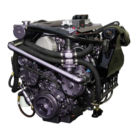
Component Identification... - Page 12 Component Identification The illustrations above show the general location of engine controls, engine components and their functions. These illustrations will help identify where these parts are located on the engine. Locations will vary from engine to engine.
- Page 13 The engine model number and serial number will be required when seeking information and/or ordering parts. There is a list of service dealers located at the very end of this manual. Technical support for Kodiak Marine engines can be obtained by contacting KEM Equipment Inc.
-
Page 14: Pre Operational Inspection
Remove the key from the ignition prior to any engine check or operation. Do not energize any engine prior to performing any of the following. Your KODIAK Marine Engine was inspected and test run before leaving the factory. Before operating a new engine, you must follow any pre-operational instruction. - Page 15 Inspect the spark arrester for any obstructions (Bugs, leaves etc.,) clean or Replace as needed. 11. Check the exterior of the heat exchanger. Follow and fix any leaks before continuing. 12. Check the alternator belt for any extra play; adjust as necessary. Does not apply to all engines.
-
Page 16: Malfunction Indicator Light (Mil)
MALFUNCTION INDICATOR LIGHT Caution- Notice to Builder/Installer This engine requires use of a MIL. A MIL (Malfunction Indicator Lamp) must be installed with this engine to be in compliance with EPA and CARB regulations. There are two lights on the dash to indicate engine related problems. The operator is responsible to acknowledge any illuminated check engine or check gauges lights during the course of engine operation. -
Page 17: Starting The Engine
STARTING THE ENGINE Prior to starting the engine the following must be performed. 1. Check engine oil level. 2. Check for fuel leaks. 3. Run bilge blower for a minimum of 10 minutes 4. Check Coolant level 5. Check bilge for excess water before starting engine WARNING: The bilge can accumulate explosive fumes. -
Page 18: Starting Mode Fuel Injection
WARNING: Extreme High Fuel Rail Pressure. The SIDI Fuel Injectors and fuel rail have extreme high fuel pressures. Do not attempt to remove or service these parts. This poses a potentially hazardous situation that if not avoided, could result in severe personal injury or death, damage to engine and or property. -
Page 19: Stopping The Engine
STOPPING THE ENGINE NORMAL CONDITIONS Let the engine idle for at least one minute prior to stopping the engine to reduce residual heat in engine components. Not doing this will not harm anything, but gives the engine a chance to reduce the temperature of many components. -
Page 20: Maintenance Instructions
MAINTENANCE INSTRUCTIONS WARNING: Extreme High Fuel Rail Pressure. The SIDI Fuel Injectors and fuel rail have extreme high fuel pressures. Do not attempt to remove or service these parts. This poses a potentially hazardous situation that if not avoided, could result in severe personal injury or death, damage to engine and or property. - Page 21 4.3L SIDI GENERAL ENGINE SPECIFICATIONS ENGINE TYPE GM LV1 V6 OHV COOLANT CAPACITY 4 US GALLONS RECOMMENDED COOLANT DEXCOOL 50/50 MIX HIGH PRESSURE FUEL FILTER/REGULATOR NAPA #3737 SPARK PLUGS AC DELCO #41-114 GM #12622441 SPARK PLUG GAP 1.025 mm .040 +/- .002 SPARK ARRESTOR A7600ESV38 OIL PAN CAPACITY...
- Page 22 5.3L SIDI GENERAL ENGINE SPECIFICATIONS ENGINE TYPE GM L83 V8 OHV COOLANT CAPACITY 5 US GALLONS RECOMMENDED COOLANT DEXCOOL 50/50 MIX HIGH PRESSURE FUEL FILTER/REGULATOR NAPA #3737 SPARK PLUGS AC DELCO #41-114 GM #12622441 SPARK PLUG GAP 1.025 mm .040 +/- .002 SPARK ARRESTOR A7600ESV38 OIL PAN CAPACITY...
- Page 23 6.2L SIDI GENERAL ENGINE SPECIFICATIONS ENGINE TYPE GM L86 V8 OHV COOLANT CAPACITY 5 US GALLONS RECOMMENDED COOLANT DEXCOOL 50/50 MIX HIGH PRESSURE FUEL FILTER/REGULATOR NAPA #3737 SPARK PLUGS AC DELCO #41-114 GM #12622441 SPARK PLUG GAP 1.025 mm .040 +/- .002 SPARK ARRESTOR F040J6 OIL PAN CAPACITY...
- Page 24 MAINTENANCE SCHEDULE SERVICE INTERVAL ENGINE CHECK POINTS EVERY 25 EVERY 50 EVERY 75 EVERY 100 EVERY 150 EVERY 200 EVERY 300 EVERY 400 DAILY HOURS HOURS HOURS HOURS HOURS HOURS HOURS HOURS GENERAL MAINTENANCE PRIOR TO ANY SERVICE OR MAINTENANCE ACTIVITY Inspect fuel system for leaks Inspect engine for fluid leaks Check engine oil...
-
Page 25: Changing Engine Oil And Filter
CHANGING ENGINE OIL AND FILTER Under normal operating conditions, the engine oil and filter must be changed every 100 hours or every 12 months whichever occurs first. Use of premium quality oil and filters is recommended. The oil and filter should be changed more often if the engine is operating in severe conditions, such as dirty areas, or during cold weather. -
Page 26: Oil Filter
Oil Filter NOTE: Ensure the old filter gasket is removed prior to installing the new filter. The Kodiak GM Powertrain engines use an AC Delco (or equivalent) oil filter as original equipment. An equivalent oil filter must be used when servicing the engine (see Engine Specifications starting on page 21 for the recommended oil filter for your engine). -
Page 27: Cooling System
COOLING SYSTEM KEM Equipment and GM Powertrain recommends the use of coolant in all DEX COOL engines. A 50/50 mixture is recommended. WARNING: Engine Damage may occur: All Generation V GM engines must be vacuum filled with coolant. If you need assistance or have questions call your local service dealer. -
Page 28: Heat Exchanger
Make sure the belt tensioner is within the proper operating range. Kodiak Marine engines utilize serpentine belts on the front of the engine. This type of belt system incorporates a belt-tensioning device that keeps the belt at the proper tension. This belt should be checked routinely for cracks or ‘checking’... -
Page 29: Fuel Injection System
FUEL INJECTION SYSTEM WARNING: Extreme High Fuel Rail Pressure. The SIDI Fuel Injectors and fuel rail have extreme high fuel pressures. Do not attempt to remove or service these parts. This poses a potentially hazardous situation that if not avoided, could result in severe personal injury or death, or damage to engine and or property. -
Page 30: Fuel Recommendation
Power Loss at Higher Elevations Fuel injected engines will lose 3.5% power for every 1000 feet the engine is operated above sea level. All fuel injection systems installed by KEM Equipment, Inc. are equipped with a “manifold absolute pressure sensor” (MAP Sensor). -
Page 31: Ignition System
IGNITION SYSTEM WARNING: High voltage ignition system. Electrical shock hazard. WARNING: The bilge can accumulate explosive fumes. The bilge blower will evacuate the fumes. The bilge blower must be run for a minimum of 10 minutes prior to cranking the engine. Type of Ignition System The ignition on Kodiak SIDI engines are controlled by a MEFI 7 ECM, and do not use a distributor. -
Page 32: Troubleshooting
TROUBLESHOOTING WARNING: The bilge can accumulate explosive fumes. The bilge blower will evacuate the fumes. The bilge blower must be run for a minimum of 10 minutes prior to cranking the engine. A Malfunction Indicator Light must be installed with this engine to be compliant NOTE: with EPA and CARB regulations. -
Page 33: Engine Does Not Crank
Engine Does Not Crank WARNING: Make sure there are no fuel leaks before going any further. Clean up any spills and always work in a well-ventilated area. WARNING: To avoid any electrical injuries always replace any broken wires before proceeding. WARNING: The bilge can accumulate explosive fumes. - Page 34 Engine Cranks but Does Not Start CAUTION: Failure to change the fuel system filter as recommended can result in premature failure of the fuel injection system components. WARNING: Use extreme care when changing the fuel filter. Gasoline is highly flammable and under pressure. It should not be exposed to open flame, sparks, or hot engine components.
-
Page 35: Engine Runs Hot
Engine Runs Hot WARNING: Never remove the radiator cap under any condition while the engine is operating. Failure to follow these instructions could result in damage to the cooling system, engine, or cause personal injury. WARNING: The bilge can accumulate explosive fumes. The bilge blower will evacuate the fumes. -
Page 36: Emissions
EMISSIONS WARNING: PROPER USE Any unauthorized modifications to or use of this engine outside its specified mechanical, electrical, or other operating limits may cause personal injury and/or property damage, including damage engine. Any such unauthorized modifications: (i) constitute "misuse" and/or "negligence" within the meaning of the product warranty thereby excluding warranty coverage for any resulting damage, and (ii) invalidate product certifications or listings. -
Page 37: Storage
STORAGE (Lay-Up) ONE MONTH 1. Check coolant protection and fluid levels. 2. Add proper amount of marine formula Stabil fuel additive or equivalent to the fuel tank. 3. Start the engine 4. Treat upper cylinders by spraying engine fogger or equivalent into the air intake for about one minute. -
Page 38: Periodic Maintenance Inspections
100, 400, 500, 800, 900, Hour Inspection WARNING: Make sure key is not in ignition and no electrical equipment is energized prior to any engine check or operation. Do not energize engine prior to performing the following steps. 1. Open engine hatch cover and let compartment air out for ten minutes or more. 2. - Page 39 800 Hour Inspection WARNING: Make sure key is not in ignition and no electrical equipment is energized prior to any engine check or operation. Do not energize engine prior to performing the following steps. 1. Open engine hatch cover and let compartment air out for ten minutes or more. 2.
- Page 40 KEM Equipment, Inc. / Kodiak Marine cannot deny warranty solely for the lack of receipts or your failure to ensure the performance of all scheduled maintenance.
- Page 41 Health and Safety Code; and, (2) Free from defects in materials and workmanship that cause the failure of a warranted part to be identical in all material respects to that part as described in KEM Equipment Inc. / Kodiak Marine’s application for certification.
- Page 42 (7) KEM Equipment, Inc. / Kodiak Marine is liable for damages to other engine components proximately caused by a failure under warranty of any warranted part. (8) Throughout the engine’s warranty period defined above, KEM Equipment, Inc. / Kodiak Marine will maintain a supply of warranted parts sufficient to meet the expected demand for such parts.
- Page 43 The repair or replacement of any warranted part otherwise eligible for warranty coverage may be excluded from such warranty coverage if KEM Equipment, Inc. / Kodiak Marine demonstrates that the engine has been abused, neglected, or improperly maintained, and that such abuse, neglect, or improper maintenance was the direct cause of the need for repair or replacement of the part.
-
Page 44: Warranty
This limited warranty applies to the first retail purchaser and each subsequent owner during the applicable warranty time period. • Kodiak Marine will repair or replace, at its option, any part that is proven to be defective in material or workmanship under normal use during the applicable warranty time period. - Page 45 • GROWTH OF MARINE ORGANISMS ON MOTOR SURFACES, EXTERNAL OR INTERNAL DISCLAIMER OF CONSEQUENTIAL DAMAGE AND LIMITATION OF IMPLIES WARRANTIES: Kodiak Marine DISCLAIMS ANY RESPONSIBILITY FOR LOSS OF TIME OR USE OF THE INBOARD, REVENUE, OR THE EQUIPMENT IN, WHICH THE INBOARD IS INSTALLED, TRANSPORTATION, COMMERCIAL LOSS, OR ANY OTHER INCIDENTAL OR CONSEQUENTIAL DAMAGE.
-
Page 46: Powertrain On Board Diagnostic (Obd) System Check
ON BOARD DIAGNOSTIC (OBD) MEFI CONTROLLED MARINE ENGINE Fire, Shock, and Burn Danger: When performing any diagnostics or WARNING: service work use caution. This system has extreme fuel pressures and a high voltage ignition. Electronic controls contain static-sensitive parts. Observe the following CAUTION: precautions to prevent damage to these parts. - Page 47 7. Inspect for aftermarket devices that could affect the operation of the system. 8. Search for applicable service bulletins. 9. Install a scan tool. Verify that the scan tool powers up. 10. Ignition ON, Engine OFF, verify communication with all of the control modules on the vehicle.
-
Page 48: Diagnostic Codes
DIAGNOSTIC ERROR CODES: SPN 94 SPN Descriptors SPN 94 FMI 3: Fuel Pressure Sensor Voltage Above Normal or Shorted High SPN 94 FMI 4: Fuel Pressure Sensor Voltage Below Normal or Shorted Low SPN 94 FMI 15: Fuel Pressure Data Valid But Above Normal Range-Least Severe Level SPN 94 FMI 17: Fuel Pressure Data Valid But Below Normal Range-Least Severe Level SPN 98 SPN Descriptor... - Page 49 SPN 108 SPN Descriptors SPN 108 FMI 2: Barometric Pressure (BARO) Sensor Voltage Data Erratic, Intermittent or Incorrect SPN 108 FMI 3: Barometric Pressure (BARO) Sensor Voltage Above Normal or Shorted High SPN 108 FMI 4: Barometric Pressure (BARO) Sensor Voltage Below Normal or Shorted Low SPN 108 FMI 10: Barometric Pressure (BARO) Sensor Abnormal Rate of Change SPN 110 SPN Descriptors...
- Page 50 SPN 651, 652, 653, 654, 655, 656, 657, or 658 SPN Descriptors SPN 651 FMI 3: Fuel Injector 1 Voltage Above Normal or Shorted High SPN 651 FMI 5: Fuel Injector 1 Current Below Normal or Open Circuit SPN 652 FMI 3: Fuel Injector 2 Voltage Above Normal or Shorted High SPN 652 FMI 5: Fuel Injector 2 Current Below Normal or Open Circuit SPN 653 FMI 3: Fuel Injector 3 Voltage Above Normal or Shorted High SPN 653 FMI 5: Fuel Injector 3 Current Below Normal or Open Circuit...
- Page 51 SPN 65559 SPN Descriptors SPN 65559 FMI 11: CAN Bus Hardware Fault Root Cause Unknown SPN 65560 SPN Descriptors SPN 65560 FMI 9: CAN Bus Governor Command Abnormal Update Rate SPN 65561, 65562, 65563, or 65564 SPN Descriptors SPN 65561 FMI 0: Oxygen Sensor Bank A Sensor 1 Data Valid But Above Normal SPN 65561 FMI 1: Oxygen Sensor Bank A Sensor 1 Data Valid But Below Normal SPN 65561 FMI 3: Oxygen Sensor Bank A Sensor 1 Voltage Above Normal or Shorted High SPN 65561 FMI 4: Oxygen Sensor Bank A Sensor 1 Voltage Below Normal or Shorted Low...
- Page 52 SPN 65570 SPN Descriptors SPN 65570 FMI 2: Cam Phaser W Data Erratic, Intermittent, or Incorrect SPN 65570 FMI 4: Cam Phaser W Voltage Below Normal or Shorted Low SPN 65570 FMI 5: Cam Phaser W Short High or Open SPN 65570 FMI 7: Cam Phaser W Accuracy Mechanical System Not Responding or Out of Adjustment SPN 65590, 65591, 65592, 65593, 65594, 65595, 65596, 65597, 65598, or...
- Page 53 SPN 65620 or 65621 SPN Descriptors SPN 65620 FMI 4: 5 Volt Reference A Circuit Voltage Below Normal or Shorted Low SPN 65621 FMI 4: 5 Volt Reference B Circuit Voltage Below Normal or Shorted Low SPN 65671 or 65672 SPN Descriptors SPN 65671 FMI 0: Catalytic Converter A Temperature Sensor Data Valid But Above Normal SPN 65671 FMI 1: Catalytic Converter A Temperature Sensor Data Valid But Below Normal...
- Page 54 SPN 65701 or 65702 SPN Descriptors SPN 65701 FMI 31: General Warning Sensor 1 Not Available SPN 65702 FMI 31: General Warning Sensor 2 Not Available SPN 65710 SPN Descriptors SPN 65710 FMI 31: Emergency Stop Warning Not Available SPN 65723 SPN Descriptors SPN 65723 FMI 2: Camshaft Position (CMP) Sensor Circuit Data Erratic, Intermittent or Incorrect...
- Page 55 SPN 66005 SPN Descriptor SPN 66005 FMI 3: Governor Status Lamp (GSL) Voltage Above Normal or Shorted High SPN 66005 FMI 5: Governor Status Lamp (GSL) Current Below Normal or Open Circuit SPN 66006 SPN Descriptor SPN 66006 FMI 3: DTC Lamp 3 Voltage Above Normal or Shorted High SPN 66006 FMI 5: DTC Lamp 3 Current Below Normal or Open Circuit SPN 66007 SPN Descriptor...
- Page 56 SPN 66018 SPN Descriptor SPN 66018 FMI 3: Tachometer Voltage Above Normal or Shorted High SPN 66018 FMI 5: Tachometer Current Below Normal or Open Circuit SPN 66019 or 66020 SPN Descriptors SPN 66019 FMI 3: Oxygen Sensor Bank A Sensor 1 Heater Voltage Above Normal or Shorted High SPN 66019 FMI 5: Oxygen Sensor Bank A Sensor 1 Heater Current Below Normal or Open Circuit...
- Page 57 SPN 66040-66043 SPN Descriptor SPN 66040 FMI 3: OEM Output Driver 1 Voltage Above Normal or Shorted High SPN 66040 FMI 5: OEM Output Driver 1 Current Below Normal or Open Circuit SPN 66041 FMI 3: OEM Output Driver 2 Voltage Above Normal or Shorted High SPN 66041 FMI 5: OEM Output Driver 2 Current Below Normal or Open Circuit SPN 66042 FMI 3: OEM Output Driver 3 Voltage Above Normal or Shorted High SPN 66042 FMI 5: OEM Output Driver 3 Current Below Normal or Open Circuit...
-
Page 58: Notice To Builders And Service Dealers
Notice to Builders and Service Dealers Generation V Engine Coolant Filling Procedure for the following GM engines: Kodiak GM 4.3L DI Kodiak GM 5.3L DI Kodiak GM 6.2L DI A heat exchanger and engine block coolant fill and air lock removal tool is necessary and must be used to purge the air lock from the new Generation V GM engines during filling or the refilling of coolant. -
Page 59: Service Dealer Locations
UNITED STATES Alaska Idaho Anchorage Boise Silver Streak 907-344-6151 Whitewater Marine 208-377-5110 Professional Marine 907-562-2471 Lewiston Cordova Riverview Marina/ Custom Weld 800-859-0356 Harbor Hydraulics 907-424-3472 Michigan North Pole Arctic Marine 907-488-5242 Marne Wasilla Camp & Cruise 616-677-1274 Valley Diesel and Marine 907-373-2613 Wasilla Arctic Cat 907-376-5845 Montana Billings... - Page 60 Oregon City British Columbia Oregon City Marine 503-656-4276 Abbotsford BC Portland River City Marine 604-852 8599 Advanced Marine 503-762-2294 Pacific Power Boats 503-288-9350 Chilliwack, BC Sigler Marine 503-252-5431 Cascade Supply & Marine 800-663-2269 Ventures River Boats 604-824-1498 Salem Dennis' Boat Shop 503-363-2898 Kamloops BC South Beach River City Marine 250-828 0858...
- Page 61 FAILURE TO INSTALL THESE MALFUNCTION INDICATOR LIGHTS WILL VOID ALL ENGINE WARRANTIES The wiring schematics included in the Kodiak Marine Operators Manuals show the correct wiring at the ECM and the Customer Interface Connector. TAG PART # KM10539 IS INSTALLED AT THE STARTER ON THE BATTERY CABLE TERMINAL AS A CAUTION;...
Need help?
Do you have a question about the KODIAK MARINE and is the answer not in the manual?
Questions and answers
What oil filter do I need for my kodiak350
The KEM MARINE for a Kodiak 350 uses an AC Delco (or equivalent) oil filter as original equipment. An equivalent oil filter must be used when servicing the engine. Refer to the engine specifications section for the exact recommended oil filter.
This answer is automatically generated