
Related Manuals for KEM KODIAK MARINE


Summary of Contents for KEM KODIAK MARINE
- Page 1 KODIAK MARINE CERTIFIED SUPERCHARGED 6.2L LSA ERSONAL INJURY KEM EQUIPMENT INC 10800 SW HERMAN RD. TUALATIN, OR. 97062 PH# (503) 692-5012 FAX# (503) 692-1098 KM10929 www.kemequipment.com...
- Page 3 Installation Instructions For the Builder/Installer KEM Equipment Inc. would like to congratulate you on your decision to recommend the Supercharged LSA Marine engine to your valued customer. The Kodiak 6.2L LSA Supercharged Marine fuel system, once properly set up, will give your customer many years of trouble free service.
- Page 4 Plumbing: The fuel supply pick up tube, fuel lines, and fittings shall be no smaller than ½” inside diameter between the fuel tank and Aero Motive high-pressure fuel pump. The fuel pump must also have the supplied 100 Micron filter installed on the inlet side of the fuel pump. When using an auxiliary engine such as an outboard motor, never plumb or tee into the main engine fuel system.
- Page 5 EMISSIONS RELATED, OR VITAL ENGINE COMPONENT FAILURE. FAILURE TO INSTALL THESE MALFUNCTION INDICATOR LIGHTS WILL VOID ALL ENGINE WARRANTIES. wiring schematics included in the Kodiak Marine Operators Manuals show the correct wiring at the ECM and the Customer Interface Connector. TAG PART # KM10539 IS INSTALLED AT THE STARTER ON THE BATTERY CABLE TERMINAL AS A CAUTION;...
- Page 6 WARNING: ELECTRICAL SHOCK HAZARD The ignition system can cause severe shock if proper precautions are not taken. WARNING: OVERSPEED PROTECTION The engine is equipped with an overspeed shutdown mode to protect against damage to the engine with possible personal injury, loss of life, or property damage.
- Page 7 WARNING: indicates a potentially hazardous situation, which, if not avoided, could result in death or serious injury. CAUTION: indicates a potentially hazardous situation, which, if not avoided, could result in damage to engine or property NOTE: provides other helpful information that does not fall under the warning or caution categories.
-
Page 8: Table Of Contents
TABLE OF CONTENTS INTRODUCTION Page 10 How to use this Manual ENGINE IDENTIFICATION Page 12-14 Model Identification Parts and Service Service Literature Component Identification MALFUNCTION INDICATOR LIGHT (MIL) Page 15 STARTING THE ENGINE Page 16 STOPPING THE ENGINE Page 17 Normal Conditions MAINTENANCE INSTRUCTIONS Page 18-19... - Page 9 FUEL INJECTION SYSTEM Page 24-26 Fuel Pump Fuel Filter Fuel Pressure Regulator Fuel Pressure Fuel Recommendations Fuel Type Fuel Quality Changes Power Loss at Higher Elevations IGNITION SYSTEMS Page 27 Type of Ignition System Spark Plugs STORAGE Page 28-31 Lay up Inspections TROUBLESHOOTING Page 32...
-
Page 10: Introduction
Always observe required scheduled maintenance activities as outlined. Never attempt to correct problems or repairs for which you are not qualified. At the end of this manual, you will find a list of qualified Kodiak marine service dealers to assist you in your area. -
Page 11: How To Use This Manual
How to Use this Manual This manual contains instructions on the safe operation and preventive maintenance of your Kodiak marine engine. We urge you to read this manual prior to start up of the engine. The Table of Contents permits you to quickly open the manual to any section. KEM Equipment, Inc. -
Page 12: Engine Identification
The engine model number and serial number will be required when seeking information and/or ordering parts. Technical support for Kodiak Marine engines can be obtained by contacting KEM Equipment Inc. 503-692-5012 Service Literature By contacting our Parts Department you can purchase parts and Service manuals for Kodiak Marine engines. -
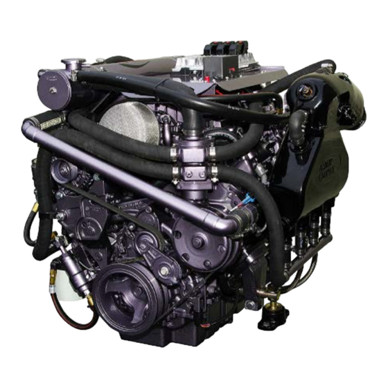
Page 13: Component Identification
Component Identification... - Page 14 1 HEAT EXCHANGER (INTERCOOLER/OIL COOLER) 2 HEAT EXCHANGER (ENGINE MAIN) 3 WATER PUMP (INTERCOOLER) 4 RESERVOIR (INTERCOOLER) 5 PUMP / HEAT EXCHANGER MOUNT 6 COOLANT TEE 7 COOLANT TRANSFER PIPE (OUT) 8 COOLANT TRANSFER PIPE (IN) 9 COOLANT OVERFLOW RESERVOIR 10 COIL PACK 11 MEFI V ECM 12 ECM VIBRATION ISOLATORS...
-
Page 15: Malfunction Indicator Light (Mil)
MALFUNCTION INDICATOR LIGHT NOTE: If the Check Engine light is illuminated, it will remain on until the problem is corrected and the engine has gone through three consecutive warm up cycles, or if the light has been cleared by a service technician with a scan tool. One warm up cycle is a starting temperature close to ambient increasing to operating temperature. -
Page 16: Starting The Engine
STARTING THE ENGINE Prior to starting the engine the following must be performed. Check engine oil level. Check for fuel leaks. Run bilge blower for a minimum of 10 minutes. Run bilge pump to remove any excess water, follow and repair any leaks. WARNING: The bilge can accumulate explosive fumes. -
Page 17: Stopping The Engine
STOPPING THE ENGINE WARNING: The engine may continue to run after ignition is turned off, turn the ignition switch immediately to ON and allow the engine to idle until it has cooled enough to stop. WARNING: Avoid injury when checking a hot engine. Allow the engine to cool down before removing the heat exchanger cap. -
Page 18: Maintenance Instructions
MAINTENANCE INSTRUCTIONS CAUTION: Neglecting proper maintenance can cause premature engine component failures. Initial Start-Up Maintenance The initial start-up checks must be made before putting the engine into service. Please refer to the Maintenance Schedule on page 37 and perform the initial start-up operations in the sequence shown in column 1. - Page 19 Adding Engine Oil It is normal to add some oil in the period of time between oil changes. The amount will vary with the severity of operation. When adding or replacing engine oil, be sure the oil meets or exceeds the recommended specification. NOTE: Use only Mobil 1 5W-30 full synthetic or equivalent motor oil.
-
Page 20: Changing Engine Oil And Filter
CHANGING ENGINE OIL AND FILTER Engine Oil Quality NOTE: To achieve proper engine performance and durability, it is important that you use only engine lubricating oils of the correct type in your engine. Quality oil also provides maximum efficiency for crankcase ventilation systems, which reduces pollution. -
Page 21: Engine Flame Arrestor
ENGINE FLAME ARRESTOR CAUTION: Service the flame arrestor more frequently under severely dusty or dirty conditions. Your flame arrestor filters air entering the engine induction system and acts as a silencer. Air that contains dirt and grit produces an abrasive fuel mixture and can cause severe damage to the cylinder walls and piston rings. -
Page 22: Cooling System
(except in freezing temperatures), but replace it with the specified coolant as quickly as possible to avoid damage to the system. KEM Equipment and General Motors recommends the use of DEX-COOL only. Do not use alcohol or methanol antifreeze, or mix them with specified coolant. -
Page 23: Heat Exchanger Plumbing
Heat exchanger Plumbing Serpentine Belt Some GM Powertrain engines utilize serpentine belts on the front of the engine. This type of belt system incorporates a belt-tensioning device that keeps the belt adjusted to the proper tension. No manual adjustments are necessary. This belt should be inspected routinely for cracks or ‘checking’... -
Page 24: Fuel Injection System
FUEL INJECTION SYSTEM CAUTION: Failure to change the fuel system filter as recommended can result in premature failure of fuel injection system components. WARNING: Use extreme care when changing the fuel filter. Gasoline is highly flammable and under pressure. It should not be exposed to open flame, sparks, or hot engine components. -
Page 25: Fuel Filter
The fuel pressure is monitored by the ECM and an electronic fuel pressure sensor installed on the fuel rail. The fuel pressure regulator is set at the KEM Manufacturing Facility and is non-adjustable. If in the event the fuel pressure is below or above the minimum maximum set pressure, the MIL light will illuminate and the engine will go into limp mode. -
Page 26: Fuel Recommendations
Fuel injected engines will lose 3.5% power for every 1000 feet the engine is operated above sea level. All fuel injection systems installed by KEM Equipment, Inc. are equipped with a “manifold absolute pressure sensor” (MAP Sensor). The MAP sensor senses barometric pressure and automatically corrects the fuel system calibration for changes in altitude. -
Page 27: Ignition Systems
IGNITION SYSTEM WARNING: High voltage ignition system. Electrical shock hazard. WARNING: The bilge can accumulate explosive fumes. The bilge blower will evacuate the fumes. The bilge blower must be run for a minimum of 10 minutes prior to cranking the engine. Type of Ignition System This engine is equipped with a distributor-less coil near plug ignition system Spark Plugs... -
Page 28: Storage
Storage (Lay-Up)-One Month CAUTION: Make sure the water side of heat exchanger are drained when ambient temperature is below 32 Degrees F. Start the engine Open throttle for a short burst of speed Shut off fuel supply to the engine, run engine until completely out of gasoline. Shutoff engine. - Page 29 100,300,500,700,900-Hour Inspection WARNING: Make sure key is not in ignition and no electrical equipment is energized prior to any engine check or operation. Do not energize engine prior to performing the following steps. Open engine hatch cover and let compartment air out for ten minutes or more. Make sure that no electrical equipment is energized Change engine oil and filter.
- Page 30 400-Hour Inspection Perform the following inspection on your engine at the 400-hour interval. WARNING: Make sure key is not in ignition and no electrical equipment is energized prior to any engine check or operation. Do not energize engine prior to performing the following steps.
- Page 31 800 Hour Inspection Perform the following inspection at 800-hour intervals. WARNING: Make sure key is not in ignition and no electrical equipment is energized prior to any engine check or operation. Do not energize engine prior to performing the following steps. Open engine hatch cover and let compartment air out for ten minutes or more.
-
Page 32: Troubleshooting
TROUBLESHOOTING WARNING: The bilge can accumulate explosive fumes. The bilge Blower will evacuate the fumes. The bilge Blower must be run for a minimum of 10 minutes prior to cranking the engine. The largest percentage of all malfunctioning equipment will be due to simple or small problems. -
Page 33: Diagnosis
DIAGNOSIS WARNING: Make sure there are no fuel leaks before going any further. Clean up any spills and always work in a well-ventilated area. WARNING: To avoid any electrical injuries always replace any broken wires before proceeding. WARNING: The bilge can accumulate explosive fumes. The bilge blower will evacuate the fumes. - Page 34 Engine Cranks, Does Not Start CAUTION: Failure to change the fuel system filter as recommended can result in premature failure of fuel injection system components. WARNING: Use extreme care when changing the fuel filter. Gasoline is highly flammable and under pressure. It should not be exposed to open flame, sparks, or hot engine components.
-
Page 35: Engine Runs Hot
Engine Runs Hot WARNING: Never remove the radiator cap under any condition while the engine is operating. Failure to follow these instructions could result in damage to the cooling system, engine, or cause personal injury. WARNING: The bilge can accumulate explosive fumes. The bilge blower will evacuate the fumes. -
Page 36: Specifications
SPECIFICATIONS QUICK REFERENCE GUIDE Engine 6.2L ENGINE OIL MOBIL 1 5W-30 ONLY OIL FILTER PF-2 (REMOTE MOUNT) IN-LINE FUEL FILTER KM10122 WATER SEPARATOR 3120R-RAC-32 SPARK ARRESTER N7600ESV38 SPARK PLUGS 11610259 SPARK PLUG GAP .040 FUEL PUMP 1824270300-7 FUEL PRESSURE REGULATOR 1544270200-5 MAIN BELT 25-060685... -
Page 37: Maintenance Schedule
MAINTENANCE SCHEDULE SERVICE INTERVAL EVERY 25 EVERY 50 EVERY 75 EVERY 100 EVERY 150 EVERY 200 EVERY 300 EVERY 400 DAILY HOURS HOURS HOURS HOURS HOURS HOURS HOURS HOURS CHECK POINTS GENERAL MAINTENANCE Inspect fuel system for leaks PRIOR TO ANY SERVICE OR MAINTENANCE ACTIVITY Inspect engine for fluid leaks Check engine oil Replace engine oil and filter... -
Page 38: Warranty
• Kodiak Marine dealer; This limited warranty applies to the first retail purchaser and each subsequent owner during the applicable warranty time period. • Kodiak Marine will repair or replace, at its option, any part that is proven to be defective in material or workmanship under normal use during the applicable warranty time period. - Page 39 AIR AND FLOAT ADJUSTMENTS ARE PART OF THE INSTALLATION. DISCLAIMER OF CONSEQUENTIAL DAMAGE AND LIMITATION OF IMPLIES WARRANTIES: Kodiak Marine DISCLAIMS ANY LIABILITY FOR LOSS OF TIME OR USE OF THE INBOARD, REVENUE, OR THE EQUIPMENT IN, WHICH THE INBOARD IS INSTALLED, TRANSPORTATION, COMMERCIAL LOSS, OR ANY OTHER INCIDENTAL OR CONSEQUENTIAL DAMAGE.
-
Page 40: Diagnostic Error Codes
DIAGNOSTIC ERROR CODES WARNING: Fire, Shock, and Burn Danger: When performing any diagnostics or service work use caution. This system has extreme fuel pressures and a high voltage ignition. CAUTION: Electronic controls contain static-sensitive parts. Observe the following precautions to prevent damage to these parts. Discharge body static before handling the control (with power to the control turned off, contact a grounded surface and maintain contact while handling the control). - Page 41 If the scan tool does not power up, refer to Scan Tool Does Not Power Up. Ignition ON, Engine OFF, verify communication with all of the control modules on the vehicle. If the scan tool does not communicate with one or more of the expected control modules, refer to Scan Tool Does Not Communicate with CAN Device.
- Page 42 SPN 94 SPN Descriptors SPN 94 FMI 3: Fuel Pressure Sensor Voltage Above Normal or Shorted High SPN 94 FMI 4: Fuel Pressure Sensor Voltage Below Normal or Shorted Low SPN 94 FMI 15: Fuel Pressure Data Valid But Above Normal Range-Least Severe Level SPN 94 FMI 17: Fuel Pressure Data Valid But Below Normal Range-Least Severe Level SPN 98...
- Page 43 SPN 108 SPN Descriptors SPN 108 FMI 2: Barometric Pressure (BARO) Sensor Voltage Data Erratic, Intermittent or Incorrect SPN 108 FMI 3: Barometric Pressure (BARO) Sensor Voltage Above Normal or Shorted High SPN 108 FMI 4: Barometric Pressure (BARO) Sensor Voltage Below Normal or Shorted SPN 108 FMI 10: Barometric Pressure (BARO) Sensor Abnormal Rate of Change SPN 110 SPN Descriptors...
- Page 44 SPN 651, 652, 653, 654, 655, 656, 657, or 658 SPN Descriptors SPN 651 FMI 3: Fuel Injector 1 Voltage Above Normal or Shorted High SPN 651 FMI 5: Fuel Injector 1 Current Below Normal or Open Circuit SPN 652 FMI 3: Fuel Injector 2 Voltage Above Normal or Shorted High SPN 652 FMI 5: Fuel Injector 2 Current Below Normal or Open Circuit SPN 653 FMI 3: Fuel Injector 3 Voltage Above Normal or Shorted High SPN 653 FMI 5: Fuel Injector 3 Current Below Normal or Open Circuit...
- Page 45 SPN 65541, 65542, 65543, 65544, 65545, 65546, 65547, or 65548 SPN Descriptors SPN 65541 FMI 4: Ignition Coil 1 Voltage Below Normal or Shorted Low SPN 65541 FMI 5: Ignition Coil 1 Current Below Normal or Open Circuit SPN 65542 FMI 4: Ignition Coil 2 Voltage Below Normal or Shorted Low SPN 65542 FMI 5: Ignition Coil 2 Current Below Normal or Open Circuit SPN 65543 FMI 4: Ignition Coil 3 Voltage Below Normal or Shorted Low SPN 65543 FMI 5: Ignition Coil 3 Current Below Normal or Open Circuit...
- Page 46 SPN 65570 SPN Descriptors SPN 65570 FMI 2: Cam Phaser W Data Erratic, Intermittent, or Incorrect SPN 65570 FMI 4: Cam Phaser W Voltage Below Normal or Shorted Low SPN 65570 FMI 5: Cam Phaser W Short High or Open SPN 65570 FMI 7: Cam Phaser W Accuracy Mechanical System Not Responding or Out of Adjustment SPN 65590, 65591, 65592, 65593, 65594, 65595, 65596, 65597, 65598, or...
- Page 47 SPN 65601, 65602, or 65610 SPN Descriptors SPN 65601 FMI 2: Throttle Position (TP) Sensor 2 Data Erratic, Intermittent or Incorrect SPN 65602 FMI 2: Throttle Position (TP) Sensor 1 Data Erratic, Intermittent or Incorrect SPN 65610 FMI 2: Throttle Position (TP) Sensor 1 and 2 Data Erratic, Intermittent or Incorrect SPN 65604, 65605, or 65613 SPN Descriptors...
- Page 48 SPN 65701 or 65702 SPN Descriptors SPN 65701 FMI 31: General Warning Sensor 1 Not Available SPN 65702 FMI 31: General Warning Sensor 2 Not Available SPN 65710 SPN Descriptors SPN 65710 FMI 31: Emergency Stop Warning Not Available SPN 65723 SPN Descriptors SPN 65723 FMI 2: Camshaft Position (CMP) Sensor Circuit Data Erratic, Intermittent or Incorrect...
- Page 49 SPN 66005 SPN Descriptor SPN 66005 FMI 3: Governor Status Lamp (GSL) Voltage Above Normal or Shorted High SPN 66005 FMI 5: Governor Status Lamp (GSL) Current Below Normal or Open Circuit SPN 66006 SPN Descriptor SPN 66006 FMI 3: DTC Lamp 3 Voltage Above Normal or Shorted High SPN 66006 FMI 5: DTC Lamp 3 Current Below Normal or Open Circuit SPN 66010 SPN Descriptor...
-
Page 50: Service Dealers
United States Salem Allen Marine 503-399-1161 Oregon Dennis' Boat Shop 503-363-2898 Bend All Season RV & Marine 541-382-5009 South Beach Central Lake Marine 541-385-7791 Newport Marine and RV 541-867-3704 Clackamas Portland Performance Marine 503-650-0001 Tigard Steven's Marine 503-620-7023 Central Point Rick's Boat Repair 541-664-8022 Coos Bay California... - Page 51 Arizona United States (CONTINUED) Bullhead Holiday RV & Marine 928-763-2322 Washington Chinook Montana Chinook Marine Repair 360-777-8361 Billings Longview Jim and Tracy's Alignment 406-259-849 Columbia Marine Services 360-430-1010 Butte Seattle Rocky Mt. RV 406-494-2555 Coastal Marine Engine 206-784-3703 Helena Tacoma One Way Marine 406-443- Harbor Services 888-627-3066 Washougal...
Need help?
Do you have a question about the KODIAK MARINE and is the answer not in the manual?
Questions and answers