Table of Contents
Advertisement
Quick Links
WARNING
PULSAR C
This equipment has been tested and found to comply with the limits for a
Class A digital device, pursuant to Part 15 of FCC Rules. These limits are
CCD Hand-Held Scanner
designed to provide reasonable protection against harmful interference in a
residential installation. This equipment generates, uses and can radiate
radio frequency energy and, if not installed and used in accordance with the
User Manual
instructions, may cause harmful interference to radio communications.
However, there is no guarantee that interference will not occur in a
particular installation. If this equipment does cause harmful interference to
radio or television reception, which can be determined by turning the
equipment off and on, the user is encouraged to try correct the interference
by one or more of the following measures:
• Reorient or relocate the receiving antenna.
• Increase the separation between the equipment and receiver.
• Connect the equipment into an outlet on a circuit different from that to
which the receiver is connected.
• Consult the dealer or an experienced radio/TV technician for help.
Metrologic Instruments GmbH
Dornier Strasse 2
82178 Puchheim
Germany
Tel +49 89 890190
Fax +49 89 89019200
www.europe.metrologic.com
© Metrologic Instruments Europe, 2001. All rights reserved
Advertisement
Table of Contents

Summary of Contents for Metrologic Hand-Held Scanner
- Page 1 • Consult the dealer or an experienced radio/TV technician for help. Metrologic Instruments GmbH Dornier Strasse 2 82178 Puchheim Germany Tel +49 89 890190 Fax +49 89 89019200 www.europe.metrologic.com © Metrologic Instruments Europe, 2001. All rights reserved...
-
Page 2: Table Of Contents
2.1 Buzzer ... 2 2.2 Indicator... 2 2.3 Scan Modes ... 2 2.4 Re-read Delay ... 3 2.5 Scanner Time-out Duration ... 3 2.6 Reading Redundancy... 4 2.7 Supported Symbologies ... 4 2.8 Negative Barcodes ... 4 3. Output Interface ... 5 3.1 Keyboard Wedge Interface ... -
Page 3: Introduction
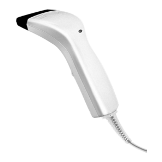
2.2 Indicator There is a dual colour indicator on top of the scanner. Normally it is off, and will turn red when there is a good read. The indicator will be green when the scanner is in configuration mode. -
Page 4: Re-Read Delay
Continuous mode for switch-less scanners. 2.4 Re-read Delay If the scanner mode is set to Continuous, Auto Power Off, Alternate, or Momentary mode, the scanner will prevent accidentally reading the same barcode twice by using a Re-read Delay (Blocking Time). The barcode must be taken away from the scanning line longer than the Re-read Delay to allow second reading of the same barcode. -
Page 5: Output Interface
Digits on Upper Row 3.1.4 Capital Lock Status In order to send alphabets with correct case, the scanner needs to know the capital lock status of the keyboard. Incorrect settings may result in reversed case of alphabets being transmitted. There are 3 options to this parameter : On, Off, or Auto Detection. -
Page 6: Inter-Character Delay
• No Flow Control • Scanner Ready : The scanner will activate the RTS signal after power on. After each good read the scanner will then wait for the CTS signal becomes active. The data will not be sent until CTS signal becomes active. -
Page 7: Codabar
4.8 EAN13 • ISBN / ISSN Conversion: If these parameters are enabled, the scanner will convert the code read into ISBN or ISSN code if the formats are correct (EAN13 codes start with 978 or 979 for ISBN, and 977 for ISSN). -
Page 8: Plessey
(two characters) will be transmitted together with data. 5. Data Output Format Data read by the scanner will be processed in the following sequence (RS- 232 and Keyboard Wedge). 1) The character substitution is performed on the barcode data. -
Page 9: Code Id
6.3 Applicable Conditions Three applicable conditions can be configured to qualify whether the data read by the scanner can be processed by the particular editing format. Data editing will not be performed unless all three applicable conditions are met. The configurable applicable conditions are described below. -
Page 10: Total Number Of Fields
If this parameter is enabled, all data read by the scanner must be processed by the editing format. If the data is not eligible for all enabled editing formats, the scanner will not accept the reading and the data will not be transmitted. -
Page 11: Enter Configuration Mode
The current setting of all scanner parameters can be sent to the host computer for user inspection. The listing is separated into ten pages. User can select the page of interest by reading the “Page x” label. The scanner cannot list setting, if Wand Emulation interface is configured. -
Page 12: Numeric Parameters
Whereas a character of Scan Code type may not have any associate key status settings. • Normal Key Type: When this label is read, the scanner will assume the following hexadecimal digits are the ASCII code of the character being programmed. And it will also clear all the associate key status settings made to the current character. -
Page 13: Exit Configuration Mode
Both the “Update”, and the “Exit Setup without Changes” labels will exit the scanner from configuration mode when they are read. These two labels differ in whether to keep the new settings on the scanner or not, as their names suggest. The scanner will respond with 6 beeps and restart itself, if either label is read.


Need help?
Do you have a question about the Hand-Held Scanner and is the answer not in the manual?
Questions and answers