Napoleon LHD45P Installation And Operating Instructions Manual
Hide thumbs
Also See for LHD45P:
- Installation and operating instructions manual (56 pages) ,
- Installation and operating instructions manual (120 pages) ,
- Installation and operating instructions manual (112 pages)
Table of Contents
Advertisement
Available languages
Available languages
Quick Links
INSTALLER: LEAVE THIS MANUAL WITH THE APPLIANCE.
CONSUMER: RETAIN THIS MANUAL FOR FUTURE REFERENCE.
NEVER LEAVE CHILDREN OR OTHER AT RISK INDIVIDUALS ALONE WITH THE APPLIANCE
CONFORMS TO AMERICAN NATIONAL STANDARDS: ANSI Z21.50, CERTIFIED TO CANADIAN CSA 2.22 FOR VENTED GAS FIREPLACES.
CERTIFIED FOR CANADA AND UNITED STATES USING ANSI/CSA METHODS.
SAFETY INFORMATION
WARNING
!
If the information in these instructions
are not followed exactly, a fi re or
explosion may result causing property
damage, personal injury or loss of life.
- Do not store or use gasoline or other fl ammable
vapors and liquids in the vicinity of this or any
other appliance.
- WHAT TO DO IF YOU SMELL GAS:
•
Do not try to light any appliance.
•
Do not touch any electrical switch; do not use
any phone in your building.
•
Immediately call your gas supplier from a
neighbour's phone. Follow the gas supplier's
instructions.
•
If you cannot reach your gas supplier, call the
fi re department.
- Installation and service must be performed by a
qualifi ed installer, service agency or the supplier.
This appliance may be installed in an aftermarket,
permanently located, manufactured home (USA
only) or mobile home, where not prohibited by
local codes.
This appliance is only for use with the type of gas
indicated on the rating plate. This appliance is
not convertible for use with other gases, unless a
certifi ed kit is used.
Decorative Product: Not for use as a heating appliance.
Phone (705)721-1212 • Fax (705)722-6031 • www.napoleonfi replaces.com • ask@napoleonproducts.com
$10.00
INSTALLATION AND
OPERATING INSTRUCTIONS
Wolf Steel Ltd., 24 Napoleon Rd., Barrie, ON, L4M 0G8 Canada /
103 Miller Drive, Crittenden, Kentucky, USA, 41030
LHD45N
NATURAL GAS
LHD45P
PROPANE
WARNING
!
A barrier designed to reduce the risk of burns from the
hot viewing glass is provided with the appliance and
shall be installed.
BARRIER
HOT GLASS WILL CAUSE
BURNS.
DO NOT TOUCH GLASS UNTIL
COOLED.
NEVER ALLOW CHILDREN TO
TOUCH GLASS.
W415-1335 / 06.27.14
1.28E
EN
FR
PG
61
Advertisement
Chapters
Table of Contents

Subscribe to Our Youtube Channel
Related Manuals for Napoleon LHD45P


Summary of Contents for Napoleon LHD45P
-
Page 1: Safety Information
BARRIER Wolf Steel Ltd., 24 Napoleon Rd., Barrie, ON, L4M 0G8 Canada / 103 Miller Drive, Crittenden, Kentucky, USA, 41030 Phone (705)721-1212 • Fax (705)722-6031 • www.napoleonfi replaces.com • ask@napoleonproducts.com $10.00... -
Page 2: Table Of Contents
TABLE OF CONTENTS NOTE: The camera icon indicates video tutorials are available as additional reference, visit http://www.napoleonfi replaces.com/category/product-support/support-centre/ INSTALLATION OVERVIEW INTRODUCTION DIMENSIONS GENERAL INSTRUCTIONS GENERAL INFORMATION RATING PLATE INFORMATION VENTING VENTING LENGTHS AND COMPONENTS FOR DIRECT VENT INSTALLATIONS TYPICAL VENT INSTALLATIONS SPECIAL VENT INSTALLATIONS 3.3.1... -
Page 3: Installation Overview
1.0 INSTALLATION OVERVIEW Mantel, see Enclosures, see the section “MINIMUM “MINIMUM CLEARANCES TO COMBUSTIBLE MANTEL ENCLOSURES” section for drywall (or CLEARANCES” other combustible material). section. Venting, see “VENTING” section. Framing, see “FRAMING” section. Framing, see “FRAMING” section. Enclosures, see the section “MINIMUM CLEARANCE TO COMBUSTIBLE... -
Page 4: Introduction
2.0 INTRODUCTION WARNING • THIS APPLIANCE IS HOT WHEN OPERATED AND CAN CAUSE SEVERE BURNS IF CONTACTED. • ANY CHANGES OR ALTERATIONS TO THIS APPLIANCE OR ITS CONTROLS CAN BE DANGEROUS AND IS PROHIBITED. • Do not operate appliance before reading and understanding operating instructions. Failure to operate appliance according to operating instructions could cause fi... -
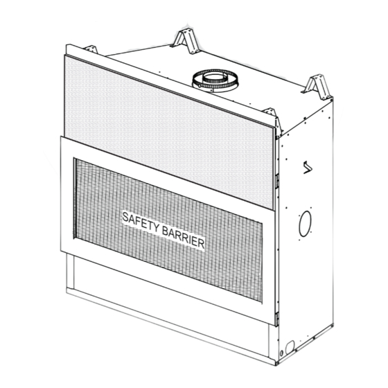
Page 5: Dimensions
DIMENSIONS 10 1/8" 257mm 7" Ø 178mm 4" Ø 102mm 40 13/16" 1036mm GAS INLET 39 5/16" SAFETY BARRIER 999mm 34 1/16" 18 7/8" 865mm 479mm 46 1/4" 1175mm 19 7/8" 505mm W415-1335 / 06.27.14... -
Page 6: General Instructions
GENERAL INSTRUCTIONS WARNING ALWAYS LIGHT THE PILOT WHETHER FOR THE FIRST TIME OR IF THE GAS SUPPLY HAS RUN OUT, WITH THE GLASS DOOR OPENED OR REMOVED. PROVIDE ADEQUATE CLEARANCE FOR SERVICING AND OPERATING THE APPLIANCE. PROVIDE ADEQUATE VENTILATION. NEVER OBSTRUCT THE FRONT OPENING OF THE APPLIANCE. OBJECTS PLACED IN FRONT OF THE APPLIANCE MUST BE KEPT A MINIMUM OF 48”... -
Page 7: General Information
GENERAL INFORMATION FOR YOUR SATISFACTION, THIS APPLIANCE HAS BEEN TEST-FIRED TO ASSURE ITS OPERATION AND QUALITY! RATES AND EFFICIENCIES Altitude (FT) 0-4,500 0-4500 Max. Input (BTU/HR) 24,000 24,000 Max. Output Steady State (BTU/HR) 17,280 17,280 Effi ciency (w/the fan on) Min. -
Page 8: Rating Plate Information
ENCASTRE 20.5” 20.5” 20.5” THE APPLIANCE MUST BE VENTED USING THE APPROPRIATE NAPOLEON VENT KITS. SEE OWNERS INSTALLATION FLOOR / PLANCHER 0” MANUAL FOR VENTING SPECIFICS. PROPER REINSTALLATION AND RESEALING IS NECESSARY AFTER SERVICING THE FRAMING (NOT INCLUDING FACE MATERIAL)/OSSATURE (MATÉRIAU DE FAÇON NON COMPRIS) (MATÉRIAU DE FAÇON NON COMPRIS) -
Page 9: Venting Lengths And Components For Direct Vent Installations
VENTING LENGTHS AND COMPONENTS FOR DIRECT VENT INSTALLATIONS NOTE: There MUST be a 25% reduction in total horizontal length (H ) when using fl ex vent. Use only Wolf Steel, Simpson Dura-Vent, Selkirk Direct Temp, American Metal Amerivent or Metal-Fab venting components. -
Page 10: Typical Vent Installations
TYPICAL VENT INSTALLATIONS NOTE: There MUST be a 25% reduction in total horizontal length (H ) when using fl ex vent. 16” (406mm) MINIMUM 40 FEET 18” (457mm) MAXIMUM (12M) (FLEX VENT) MAXIMUM 24” (610mm) MAXIMUM 3 FEET (RIGID VENT) (1M) MINIMUM 8”... -
Page 11: Special Vent Installations
SPECIAL VENT INSTALLATIONS 3.3.1 PERISCOPE TERMINATION Use the periscope kit to locate the air termination above grade. The periscope must be installed so that when fi nal grading is completed, the bottom air slot is located a minimum 12” (305m) above grade. The maximum allowable vent length is 10’ (3m) 12”... -
Page 12: Vent Terminal Clearances
VENT TERMINAL CLEARANCES COVERED BALCONY APPLICATIONS ††* = 3 feet = 2 x ACTUAL (0.9m) (4.6m) INSTALLATIONS CANADA U.S.A. 12” (305mm) 12” (305mm) Clearance above grade, veranda porch, deck or balcony. 9” 12” (305mm) Clearance to windows or doors that open. Δ... -
Page 13: Vent Application Flow Chart
VENT APPLICATION FLOW CHART TOP EXIT Horizontal Termination Vertical Termination Vertical rise is equal Vertical rise is equal Vertical rise is less Vertical rise is less to or greater than to or greater than than horizontal run than horizontal run the horizontal run the horizontal run Horizontal run +... -
Page 14: Horizontal Termination
HORIZONTAL TERMINATION NOTE: There MUST be a 25% reduction in total horizontal length (H ) when using fl ex vent. ) < (V See graph to determine the required vertical Simple venting confi guration (only one 90° elbow) rise V for the required horizontal run H 40 (12.2) 39 (11.9) - Page 15 NOTE: There MUST be a 25% reduction in total horizontal length (H ) when using fl ex vent. ) > (V See graph to determine the required vertical rise V for the Simple venting configuration (only one 90° elbow) required horizontal run H 150 (3810) 147 (3733.8) REQUIRED...
-
Page 16: Vertical Termination
VERTICAL TERMINATION NOTE: There MUST be a 25% reduction in total horizontal length (H ) when using fl ex vent. ) < (V Simple venting configurations. See graph to determine the required vertical rise V for the required horizontal run H 40 (12.2) 30 (9.1) REQUIRED... - Page 17 NOTE: There MUST be a 25% reduction in total horizontal length (H ) when using fl ex vent. ) > (V Simple venting configurations. See graph to determine the required vertical rise V for the required horizontal run H 20 (6.1) 19 (5.8) REQUIRED VERTICAL...
-
Page 18: Vertical Through Existing Chimney
3.10 VERTICAL THROUGH EXISTING CHIMNEY WARNING RISK OF FIRE! CO-AXIAL TO CO-LINEAR VENTING CONFIGURATIONS MUST ONLY BE USED IN A NON- COMBUSTIBLE CHIMNEY OR ENCLOSURE. INSTALLATION IN A COMBUSTIBLE ENCLOSURE COULD RESULT IN A FIRE. This appliance is designed to be attached to a 3” (76.2mm) co-linear aluminum fl ex vent system running the full length of a masonry chimney. -
Page 19: Vent Heat Shield Installation
3.11 VENT HEAT SHIELD INSTALLATION For shipping purposes, the heat shield has been attached on top of the appliance. If venting with a 90 degree elbow directly off of the top of the appliance, the elbow heat shield must be repositioned and secured with the two screws (supplied) as illustrated. -
Page 20: Installation
4.0 INSTALLATION WARNING ENSURE TO UNPACK ALL LOOSE MATERIALS FROM INSIDE THE FIREBOX PRIOR TO HOOKING UP THE GAS AND ELECTRICAL SUPPLY. IF YOUR APPLIANCE IS SUPPLIED WITH A REMOTE ENSURE THE REMOTE RECEIVER IS IN THE “OFF” POSITION PRIOR TO HOOKING UP THE GAS AND ELECTRICAL SUPPLY TO THE APPLIANCE. FOR SAFE AND PROPER OPERATION OF THE APPLIANCE, FOLLOW THE VENTING INSTRUCTIONS EXACTLY. -
Page 21: Horizontal Installation
4.1.1 HORIZONTAL INSTALLATION WARNING THE FIRESTOP ASSEMBLY MUST BE INSTALLED WITH THE VENT SHIELD TO THE TOP. TERMINALS MUST NOT BE RECESSED INTO A WALL OR SIDING MORE THAN THE DEPTH OF THE RETURN FLANGE OF THE MOUNTING PLATE. This application occurs when venting through an exterior wall. Having determined the correct height for the air terminal VENT location, cut and frame a hole in the exterior wall as... -
Page 22: Using Rigid Vent Components
USING RIGID VENT COMPONENTS The vent system must be supported approximately every 3 feet (0.9m) for both vertical and horizontal runs. Use Wolf Steel Ltd. support ring assembly or equivalent noncombustible strapping to maintain the minimum clearance to combustibles for both vertical and horizontal runs. All inner exhaust and outer intake vent pipe joints may be sealed using either red high temperature silicone sealant W573-0002 (not supplied) or black high temperature sealant W573-0007 Mill Pac (not supplied) with the exception of the appliance exhaust fl... -
Page 23: Extended Horizontal And Corner Terminal Installation
EXTENDED HORIZONTAL AND CORNER TERMINAL INSTALLATION A. Follow the instructions for "HORIZONTAL AIR TERMINAL INSTALLATIONS" section. AIR TERMINAL TELESCOPIC Continue adding components alternating inner rigid pipe and outer rigid pipe. Ensure SLEEVE that all inner rigid pipe and elbows have sufficient vent spacers attached and each component is sealed and securely fastened to the one prior. -
Page 24: Using Flexible Venting
USING FLEXIBLE VENTING NOTE: All vent parameters are stated for rigid venting. If using approved Wolf Steel Ltd. fl exible venting then total horizontal lengths (H ) are reduced by 25%. MOBILE HOME INSTALLATION This appliance is also certifi ed to be installed as an OEM (Original Equipment Manufacturer) installation in a manufactured home (U.S. -
Page 25: Gas Installation
GAS INSTALLATION WARNING RISK OF FIRE, EXPLOSION OR ASPHYXIATION. ENSURE THERE ARE NO IGNITION SOURCES SUCH AS SPARKS OR OPEN FLAMES. SUPPORT GAS CONTROL WHEN ATTACHING GAS SUPPLY PIPE TO PREVENT DAMAGING GAS LINE. ALWAYS LIGHT THE PILOT WHETHER FOR THE FIRST TIME OR IF THE GAS SUPPLY HAS RUN OUT WITH THE GLASS DOOR OPENED OR REMOVED. -
Page 26: Installing Non-Combustible Board
4.10 INSTALLING NON-COMBUSTIBLE BOARD WARNING A NON-COMBUSTIBLE FINISHING MATERIAL BORDER, SUCH AS BRICK, MARBLE, GRANITE, ETC. IS REQUIRED. FINISHING WITH JUST NON-COMBUSTIBLE BOARD TO THE SIDES AND TOP OF THE APPLIANCE IS NOT ALLOWED. THE SURFACE ABOVE THE APPLIANCE GETS VERY HOT. IF PROPER FINISHING MATERIALS ARE NOT USED, CRACKING CAN OCCUR. -
Page 27: Framing
5.0 FRAMING WARNING RISK OF FIRE! IN ORDER TO AVOID THE POSSIBILITY OF EXPOSED INSULATION OR VAPOUR BARRIER COMING IN CONTACT WITH THE APPLIANCE BODY, IT IS RECOMMENDED THAT THE WALLS OF THE APPLIANCE ENCLOSURE BE “FINISHED” (IE: DRYWALL / SHEETROCK), AS YOU WOULD FINISH ANY OTHER OUTSIDE WALL OF A HOME. - Page 28 WARNING DO NOT BUILD INTO THIS AREA - IT MUST BE LEFT CLEAR TO PROVIDE ADEQUATE CLEARANCE FOR THE VENT IN THIS 14” (356mm) WIDE AREA CENTERED ALONG THE FRONT OF THE FIREPLACE. NO COMBUSTIBLES ARE ALLOWED. FIREPLACE SHOULD BE IN ITS FINAL LOCATION BEFORE FRAMING.
- Page 29 MAINTAIN THESE MINIMUM CLEARANCES TO COMBUSTIBLES FROM FRAMING APPLIANCE AND VENT SURFACES: ROUGH OPENING HEIGHT WIDTH DEPTH TO CEILING SIDE TOP OF SIDES REAR CEILING FROM TOP WALL COMBUSTIBLE VENT & SIDE FROM FINISHING PIPE BOTTOM STAND- BASE OF APPLIANCE ABOVE OF VENT OFFS...
-
Page 30: Minimum Clearance To Combustible Enclosures
MINIMUM CLEARANCE TO COMBUSTIBLE ENCLOSURES IMPORTANT: The LHD45 requires a minimum inside enclosure height of 56” (1422mm), measured from the bottom of the appliance. For temperature requirements, this area must be left unobstructed. It is recommended that the enclosure be ventilated at the top and bottom to circulate the hot air. NON-COMBUSTIBLE COMBUSTIBLE SHELF... - Page 31 NON-COMBUSTIBLE 30 11/16" 780mm 14" 365mm TOP OF APPLIANCE OPENING 2" 51mm 42" 46 1/4" 1067mm 1175mm COMBUSTIBLE Finishing material may be secured directly to the appliance body where practical. W415-1335 / 06.27.14...
-
Page 32: Alcove Enclosure
ALCOVE ENCLOSURE RECESS OR ALCOVE AREA ENCLOSURE AREA APPLIANCE NOTE: Recesses or alcoves above the appliance can be made as deep as desired provided the minimum clearances to combustibles are maintained. Non-combustible material can be used, provided the minimum clearances to combustible materials are applied. The minimum enclosure volume must be increased by no less than the volume of the recess. -
Page 33: Minimum Non-Combustible Protrusion
MANTEL DIMENSIONS MUST BE Height Depth NON-COMBUSTIBLE 25 5/16” (643mm) 6” (152mm) 2” (51mm) 8” (203mm) 4” (102mm) 10” (254mm) 6” (152mm) 12” (305mm) 8” (203mm) TOP OF APPLIANCE (DOOR) OPENING BASE OF UNIT MINIMUM NON-COMBUSTIBLE PROTRUSION NOTE: Projection must be non-combustible. FROM TOP OF APPLIANCE OPENING Height Depth... -
Page 34: Finishing
6.0 FINISHING WARNING RISK OF FIRE! NEVER OBSTRUCT THE FRONT OPENING OF THE APPLIANCE. THE FRONT OF THE APPLIANCE MUST BE FINISHED WITH ANY NON-COMBUSTIBLE MATERIALS SUCH AS BRICK, MARBLE, GRANITE, ETC., PROVIDED THAT THESE MATERIALS DO NOT GO BELOW THE SPECIFIED DIMENSION AS ILLUSTRATED. DO NOT STRIKE, SLAM OR SCRATCH GLASS. -
Page 35: Battery Housing Installation
BATTERY HOUSING INSTALLATION WARNING ENSURE THE GAS AND ELECTRICAL POWER IS TURNED OFF TO THE APPLIANCE. APPLIANCE MAY BE HOT, DO NOT SERVICE UNTIL THE APPLIANCE HAS COOLED. NOTE: In the event of a power failure your appliance can be operated using the battery back-up supplied. Turn the gas and electrical power off to the appliance, before beginning installation. -
Page 36: Glass Embers
GLASS EMBERS WARNING CLEAN THE GLASS MEDIA PRIOR TO INSTALLATION. BEFORE APPLYING THE CLEANED GLASS, ENSURE THAT IT IS DRY. DO NOT CHANGE OR SUBSTITUTE THE GLASS MEDIA MATERIAL PROVIDED WITH THIS APPLIANCE. IF REPLACING, USE ONLY THE REPLACEMENT GLASS MEDIA AVAILABLE FROM YOUR AUTHORIZED DEALER / DISTRIBUTOR. -
Page 37: Optional Rock Placement
OPTIONAL ROCK PLACEMENT Randomly place the refractory rocks onto the media tray, around, but not on the burner ports or pilot mesh. Follow the instructions provided with RK62. W415-1335 / 06.27.14... -
Page 38: Optional Blower Installation
7.0 OPTIONAL BLOWER INSTALLATION WARNING RISK OF FIRE AND ELECTRICAL SHOCK. TURN OFF THE GAS AND ELECTRICAL POWER BEFORE SERVICING THIS APPLIANCE. USE ONLY WOLF STEEL APPROVED OPTIONAL ACCESSORIES AND REPLACEMENT PARTS WITH THIS APPLIANCE. USING NON-LISTED ACCESSORIES (BLOWERS, DOORS, LOUVRES, TRIMS, GAS COMPONENTS, VENTING COMPONENTS, ETC.) COULD RESULT IN A SAFETY HAZARD AND WILL VOID THE WARRANTY AND CERTIFICATION. -
Page 39: Valve Train Assembly
7.1.2 VALVE TRAIN ASSEMBLY Remove the door, see “SAFETY SCREEN AND DOOR REMOVAL / INSTALLATION” section. Remove the media tray and burner, see “BURNER REMOVAL” section. Remove the fourteen screws from the valve train assembly. Carefully lift the valve train assembly and turn off the manual shut-off valve, see “GAS INSTALLATION”... -
Page 40: Installing The Blower
INSTALLING THE BLOWER INSTALLATION TO BE DONE BY A QUALIFIED INSTALLER and must be electrically connected and grounded in accordance with local codes. In the absence of local codes, use the current CSA C22.1 Canadian electrical code in Canada or the ANSI / NFPA 70 National Electrical Code in the United States The three slots on the blower mounting bracket allow ease of adjustment when attaching the blower. -
Page 41: Electrical Connection
8.0 ELECTRICAL CONNECTION WARNING DO NOT USE THIS APPLIANCE IF ANY PART HAS BEEN UNDER WATER. CALL A QUALIFIED SERVICE TECHNICIAN IMMEDIATELY TO HAVE THE APPLIANCE INSPECTED FOR DAMAGE TO THE ELECTRICAL CIRCUIT. RISK OF ELECTRICAL SHOCK OR EXPLOSION. DO NOT WIRE 110V TO THE VALVE OR TO THE APPLIANCE WALL SWITCH. -
Page 42: Hard Wiring Connection
HARD WIRING CONNECTION It is necessary to hard wire this appliance. Permanently framing the appliance with an enclosure, requires the appliance junction box to be hard wired. This appliance must be electrically connected and grounded in accordance with local codes. In the absence of local codes, use the current CSA C22.1 Canadian electrical code in Canada or the ANSI/NFPA 70-1996 national electrical code in the United States. -
Page 43: Wiring Diagram
WIRING DIAGRAM WARNING DO NOT WIRE 110 VOLTS TO THE VALVE OR WALL SWITCH. This appliance comes equipped with a battery back-up. If this backup is used, install 4 AA batteries (not supplied) into the holder and connect to the wire harness. Place near the IPI board. Connect the battery holder to the wire harness before using the appliance. -
Page 44: Operating Instructions
9.0 OPERATING INSTRUCTIONS When lit for the fi rst time, the appliance will emit a slight odour for a few hours. This is a normal temporary condition caused by the “burn-in” of internal paints and lubricants used in the manufacturing process and will not occur again. -
Page 45: Anti Condensation Switch (Optional)
ANTI CONDENSATION SWITCH (OPTIONAL) This appliance has the option to switch from an electronic intermittent pilot ignition (IPI) to a standing pilot (ACS) for cold climates. The anti condensation switch (standing pilot) is located in the center of the control panel. Using your fi nger, fl ip the switch up for standing pilot, or down for intermittent pilot ignition. -
Page 46: Venturi Adjustment
10.3 VENTURI ADJUSTMENT This appliance has an air shutter that has been factory set open according to the chart below: VENTURI BURNER Regardless of venturi orientation, closing the air shutter will cause a more yellow flame, but can lead to carboning. Opening the air shutter will cause a more blue flame, but can cause flame lifting from the burner ports. -
Page 47: Maintenance
11.0 MAINTENANCE MAINTENANCE MAINTENANCE WARNING MAINTENANCE TURN OFF THE GAS AND ELECTRICAL POWER BEFORE SERVICING THE APPLIANCE. APPLIANCE MAY BE HOT, DO NOT SERVICE UNTIL APPLIANCE HAS COOLED. DO NOT USE ABRASIVE CLEANERS. DO NOT PAINT THE PILOT ASSEMBLY. CAUTION: Label all wires prior to disconnection when servicing controls. Wiring errors can cause improper and dangerous operation. -
Page 48: Annual Maintenance
11.2 ANNUAL MAINTENANCE WARNING THE FIREBOX BECOMES VERY HOT DURING OPERATION. LET THE APPLIANCE COOL COMPLETELY OR WEAR HEAT RESISTANT GLOVES BEFORE CONDUCTING SERVICE. NEVER VACUUM HOT EMBERS. DO NOT PAINT THE PILOT ASSEMBLY. • This appliance will require maintenance which should be planned on an annual basis. •... -
Page 49: Care Of Glass
Contact you local authorized dealer / distributor for complete cleaning instructions. This appliance is factory equipped with 5mm ceramic glass. Use only replacement glass available from your Napoleon® dealer. DO NOT SUBSTITUTE MATERIALS. 5.5.1 11.3 CARE OF PLATED PARTS If the appliance is equipped with plated parts, you must clean fi... -
Page 50: Replacements
12.0 REPLACEMENTS Contact your dealer or the factory for questions concerning prices and policies on replacement parts. Normally all parts can be ordered through your Authorized dealer / distributor. WARNING FOR WARRANTY REPLACEMENT PARTS, A PHOTOCOPY OF THE ORIGINAL INVOICE WILL BE REQUIRED TO HONOUR THE CLAIM. FAILURE TO POSITION THE PARTS When ordering replacement parts always give the following information: IN ACCORDANCE WITH THIS... -
Page 51: Overview
W415-1335 / 06.27.14... -
Page 52: Accessories
W415-1335 / 06.27.14... - Page 53 W415-1335 / 06.27.14...
-
Page 54: Valve Train Assembly
W415-1335 / 06.27.14... -
Page 55: Troubleshooting
16.0 TROUBLESHOOTING WARNING ALWAYS LIGHT THE PILOT WHETHER FOR THE FIRST TIME OR IF THE GAS SUPPLY HAS RAN OUT, WITH THE GLASS DOOR OPEN OR REMOVED. TURN OFF THE GAS AND ELECTRICAL POWER BEFORE SERVICING THE APPLIANCE. APPLIANCE MAY BE HOT, DO NOT SERVICE UNTIL APPLIANCE HAS COOLED. DO NOT USE ABRASIVE CLEANERS. - Page 56 SYMPTOM PROBLEM TEST SOLUTION Carbon is being Air shutter has become Ensure air shutter opening is free of lint or other deposited on blocked. obstructions. glass, logs, Flame is impinging on the Check that the glass, logs, rocks or media are rocks, media glass, logs, rocks, media correctly positioned.
- Page 57 SYMPTOM PROBLEM TEST SOLUTION White / grey fi lm Sulphur from fuel is being Clean the glass, see “CARE OF GLASS” section forms. deposited on glass, logs or DO NOT CLEAN GLASS WHEN HOT. combustion chamber If deposits are not cleaned off regularly, the glass surfaces.
-
Page 58: Warranty
All parts replaced under the President’s Limited Lifetime Warranty Policy are subject to a single claim. During the fi rst 10 years NAPOLEON® will replace or repair the defective parts covered by the lifetime warranty at our discretion free of charge. From 10 years to life, NAPOLEON®... -
Page 59: Service History
18.0 SERVICE HISTORY W415-1335 / 06.27.14... - Page 60 Fireplace Inserts • Charcoal Grills • Gas Fireplaces • Waterfalls • Wood Stoves Heating & Cooling • Electric Fireplaces • Outdoor Fireplaces • Gourmet Grills 24 Napoleon Road, Barrie, Ontario, Canada L4M 0G8 214 Bayview Drive, Barrie, Ontario, Canada L4N 4Y8...
- Page 61 être installés. ÉCRAN DE PROTECTION N° de série N° DE MODÈLE Wolf Steel Ltd., 24 Napoleon Rd., Barrie, ON, L4M 0G8 Canada / 103 Miller Drive, Crittenden, Kentucky, USA, 41030 Téléphone 705-721-1212 • Télécopieur 705-722-6031 • www.napoleonfoyers.com • ask@napoleon.on.ca 10,00$ 1.28D...
- Page 62 TABLE DES MATIÈRES NOTE: L'icône du camera indique que les vidéos sont disponibles comme une référence supplémentaire, visitez http://www.napoleonfi replaces.com/category/product-support/support-centre/ SURVOL DE L’INSTALLATION INTRODUCTION DIMENSIONS INSTRUCTIONS GÉNÉRALES INFORMATIONS GÉNÉRALES INFORMATION SUR LA PLAQUE D’HOMOLOGATION ÉVACUATION LONGUEURS DES CONDUITS D’ÉVACUATION ET COMPOSANTS POUR UNE ÉVACUATION DIRECTE...
-
Page 63: Survol De L'installation
1.0 SURVOL DE L’INSTALLATION Enceintes, voir la section « DÉGAGEMENTS Voir la section MINIMAUX AUX ENCEINTES « DÉGAGEMENTS COMBUSTIBLES » pour les cloisons sèches MINIMAUX DE LA (ou autres matériaux combustibles). TABLETTE » Évacuation, voir la section « ÉVACUATION ». Voir la section «... -
Page 64: Introduction
2.0 INTRODUCTION AVERTISSEMENT • CET APPAREIL EST CHAUD LORSQU’IL FONCTIONNE ET PEUT CAUSER DE GRAVES BRÛLURES EN CAS DE CONTACT. • TOUTE MODIFICATION APPORTÉE À CET APPAREIL OU AUX CONTRÔLES PEUT ÊTRE DANGEREUX ET EST INTERDIT. • Ne faites pas fonctionner l’appareil avant d’avoir lu et compris les instructions d’opération. Omettre d’utiliser l’appareil selon les instructions d’opération pourrait causer un incendie ou des blessures. -
Page 65: Dimensions
DIMENSIONS 10 1/8" 257mm 7" Ø 178mm 4" Ø 102mm 40 13/16" 1036mm ENTRÉE 39 5/16" DU GAZ ÉCRAN DE PROTECTION 999mm 34 1/16" 865mm 18 7/8" 479mm 46 1/4" 1175mm 19 7/8" 505mm W415-1335 / 06.27.14... -
Page 66: Instructions Générales
INSTRUCTIONS GÉNÉRALES AVERTISSEMENT ALLUMEZ TOUJOURS LA VEILLEUSE, QUE CE SOIT POUR LA PREMIÈRE FOIS OU LORSQUE L’APPROVISIONNEMENT EN GAZ EST ÉPUISÉ, AVEC LA PORTE VITRÉE OUVERTE OU RETIRÉE. PRÉVOYEZ UN ACCÈS SUFFISANT POUR ENTRETENIR ET OPÉRER L’APPAREIL. ASSUREZ-VOUS D'UNE QUANTITÉ SUFFISANTE D’AIR DE VENTILATION. N’OBSTRUEZ JAMAIS L’OUVERTURE DE L’APPAREIL. -
Page 67: Informations Générales
INFORMATIONS GÉNÉRALES POUR VOTRE SATISFACTION, CET APPAREIL A ÉTÉ MIS À L’ESSAI POUR CONFIRMER SON FONCTIONNEMENT ET SA QUALITÉ! APPAREIL Altitude (PI) 0-4 500 0-4 500 Débit max. (BTU/H) 24 000 24 000 Rendement maximal à régime continu 17 280 17 280 (BTU/H) Effi... -
Page 68: Information Sur La Plaque D'homologation
RECESSED DEPTH / PROFONDEUR D'ENCASTRE 20.5” 20.5” 20.5” THE APPLIANCE MUST BE VENTED USING THE APPROPRIATE NAPOLEON VENT KITS. SEE OWNERS INSTALLATION FLOOR / PLANCHER 0” MANUAL FOR VENTING SPECIFICS. PROPER REINSTALLATION AND RESEALING IS NECESSARY AFTER SERVICING THE FRAMING (NOT INCLUDING FACE MATERIAL)/OSSATURE (MATÉRIAU DE FAÇON NON COMPRIS) AÇON NON COMPRIS) -
Page 69: Longueurs Des Conduits D'évacuation Et Composants Pour Une Évacuation Directe
LONGUEURS DES CONDUITS D’ÉVACUATION ET COMPOSANTS POUR UNE ÉVACUATION DIRECTE NOTE : La course horizontale totale (HT) DOIT être réduite de 25 % lorsqu’un évent fl exible est utilisé. Utilisez uniquement des composants d’évacuation Wolf Steel, Simpson Dura-Vent, Selkirk Direct Temp, American Metal Amerivent ou Metal-Fab. -
Page 70: Fr 3.2 Installations Typiques D'évents
INSTALLATIONS TYPIQUES D’ÉVENTS NOTE : La course horizontale totale (HT) DOIT être réduite de 25 % lorsqu’un évent fl exible est utilisé. 16” (406mm) MINIMUM 40 PIEDS 18” (457mm) MAXIMUM (12M) (ÉVENT FLEXIBLE) MAXIMUM 24” (610mm) MAXIMUM 3 PIEDS (ÉVENT RIGIDE) (1M) MINIMUM 8”... -
Page 71: Installations Particulières D'évents
INSTALLATIONS PARTICULIÈRES D’ÉVENTS 3.3.1 ENSEMBLE PÉRISCOPIQUE Utilisez l’ensemble périscopique afi n de positionner la terminaison au-dessus du niveau du sol. L’ensemble périscopique doit être installé de façon à ce que la fente d’air du bas soit située à un minimum de 12 pouces (304,8mm) 12”... -
Page 72: Emplacements Et Dégagements Minimaux De La Terminaison
EMPLACEMENTS ET DÉGAGEMENTS MINIMAUX DE LA TERMINAISON ††* APPLICATIONS POUR BALCON COUVERT INSTALLATION = 3 pieds = 2 x RÉELLE (0,9m) (4,6m) CANADA É.-U. 12” 12” Dégagement au-dessus du sol, d’une véranda, d’une terrasse en bois ou d’un balcon. (304,8mm) (304,8mm) 12”... -
Page 73: Charte D'application Des Évacuations
CHARTE D’APPLICATION DES ÉVACUATIONS ÉVACUATION SUR LE DESSUS Terminaison horizontale Terminaison verticale La course verticale La course verticale La course verticale La course verticale est plus grande ou est plus grande ou est plus petite est plus petite égale à la course égale à... -
Page 74: Terminaison Horizontale
TERMINAISON HORIZONTALE NOTE : La course horizontale totale (HT) DOIT être réduite de 25 % lorsqu’un évent fl exible est utilisé. ) > (V Consultez le graphique pour déterminer la course verticale Configuration d'évacuation simple (un coude de 90° nécessaire V par rapport à... - Page 75 NOTE : La course horizontale totale (HT) DOIT être réduite de 25 % lorsqu’un évent fl exible est utilisé. ) > (V Configuration d'évacuation simple (un coude de 90° Consultez le graphique pour déterminer la course verticale seulement). nécessaire V par rapport à...
-
Page 76: Terminaison Verticale
TERMINAISON VERTICALE NOTE : La course horizontale totale (HT) DOIT être réduite de 25 % lorsqu’un évent fl exible est utilisé. ) < (V Configuration d'évacuation simple. Consultez le graphique pour déterminer la course verticale nécessaire V par rapport à la course horizontale requise H 40 (12,2) 30 (9,1) COURSE... - Page 77 NOTE : La course horizontale totale (HT) DOIT être réduite de 25 % lorsqu’un évent fl exible est utilisé. ) > (V Configuration d'évacuation simple. Consultez le graphique pour déterminer la course verticale nécessaire V par rapport à la course horizontale requise H 20 (6,1) 19 (5,8) COURSE...
-
Page 78: Terminaison Verticale À Travers Une Cheminée Existante
3.10 TERMINAISON VERTICALE À TRAVERS UNE CHEMINÉE EXISTANTE AVERTISSEMENT RISQUE D'INCENDIE! LES CONFIGURATIONS D'ÉVACUATION COAXIALES À COLINÉAIRES NE DOIVENT ÊTRE UTILISÉES QUE DANS UNE CHEMINÉE OU UNE ENCEINTE DE NATURE INCOMBUSTIBLE. UNE INSTALLATION DANS UNE ENCEINTE COMBUSTIBLE PEUT CAUSER UN INCENDIE. Cet appareil est conçu pour être raccordé... -
Page 79: Installation Du Protecteur De Conduit D'évacuation
3.11 INSTALLATION DU PROTECTEUR DE CONDUIT D’ÉVACUATION Le protecteur de conduit d’évacuation a été fi xé au-dessus de l’appareil aux fi ns de livraison. Si l’évacuation se fait avec un coude de 90 degrés directement à partir du dessus de l’appareil, le protecteur de conduit d’évacuation doit être repositionné... -
Page 80: Installation
4.0 INSTALLATION AVERTISSEMENT AVANT D’EFFECTUER LES BRANCHEMENTS POUR L’ALIMENTATION EN GAZ ET ÉLECTRIQUE, ASSUREZ-VOUS DE RETIRER TOUTE COMPOSANTE NON FIXÉE À L’INTÉRIEUR DE LA CHAMBRE DE COMBUSTION. SI VOTRE APPAREIL COMPREND UN SYSTÈME DE TÉLÉCOMMANDE, ASSUREZ-VOUS QUE LE RÉCEPTEUR EST À LA POSITION « OFF » AVANT D’EFFECTUER LES BRANCHEMENTS POUR L’ALIMENTATION EN GAZ ET ÉLECTRIQUE. -
Page 81: Installation Horizontale
4.1.1 INSTALLATION HORIZONTALE AVERTISSEMENT L’ESPACEUR COUPE-FEU DOIT ÊTRE INSTALLÉ AVEC L’ÉCRAN PROTECTEUR ORIENTÉ VERS LE HAUT. LA TERMINAISON NE DOIT PAS ÊTRE ENCHÂSSÉE DANS LE MUR OU LE REVÊTEMENT EXTÉRIEUR PLUS QUE L’ÉPAISSEUR DE LA BRIDE DE LA PLAQUE DE MONTAGE. Cette confi... -
Page 82: Installation Verticale
4.1.2 INSTALLATION VERTICALE This application occurs when venting through a roof. Installation kits for various roof pitches are available from your authorized dealer / distributor. See accessories to order specifi c kits required. A. Determine the air terminal location, cut and frame a square opening as 9 3/4”... -
Page 83: Installation De La Terminaison Horizontale
INSTALLATION DE LA TERMINAISON HORIZONTALE Mettez l’appareil en place. Mesurez VIS #10x2" la longueur d’évent requise entre la terminaison et l’appareil en tenant CALFEUTRAGE compte de la longueur additionnelle nécessaire pour la surface du mur CONDUIT fi ni et tout chevauchement de 1 RIGIDE CONDUIT INTÉRIEUR... -
Page 84: Installation De La Terminaison Verticale
INSTALLATION DE LA TERMINAISON VERTICALE Mettez l’appareil en place. CONDUIT Fixez le support de toit au toit à l’aide des vis fournies. Le support de toit INTÉRIEUR est optionnel. Dans ce cas, l’évent doit être supporté adéquatement, soit en utilisant une méthode alternative se conformant aux normes des autorités compétentes, soit en utilisant le support de toit optionnel. -
Page 85: Utilisation De Composants Flexibles D'évacuation
UTILISATION DE COMPOSANTS FLEXIBLES D’ÉVACUATION NOTE : Tous les paramètres énoncés s’appliquent aux évents rigides. Si vous utilisez des évents fl exibles Wolf Steel ltée., les courses horizontales maximales doivent être réduites de 25 %. INSTALLATION DANS UNE MAISON MOBILE Cet appareil est certifi... -
Page 86: Branchement Du Gaz
BRANCHEMENT DU GAZ AVERTISSEMENT RISQUE D'INCENDIE, D'EXPLOSION OU D'ASPHYXIE. ASSUREZ-VOUS QU'IL N'Y AIT AUCUNE SOURCE D'ALLUMAGE COMME DES ÉTINCELLES OU UNE FLAMME NUE. SOUTENEZ LE CONTRÔLE DU GAZ LORSQUE VOUS ATTACHEZ LE TUYAU POUR ÉVITER DE PLIER LA CON- DUITE DE GAZ. ALLUMEZ TOUJOURS LA VEILLEUSE, QUE CE SOIT POUR LA PREMIÈRE FOIS OU LORSQUE L’APPROVISIONNEMENT EN GAZ EST ÉPUISÉ, AVEC LA PORTE VITRÉE OUVERTE OU RETIRÉE. -
Page 87: Installation Du Matériaux Incombustible
4.10 INSTALLATION DU MATÉRIAUX INCOMBUSTIBLE WARNING UNE BORDURE DE FINITION INCOMBUSTIBLE COMME DE LA BRIQUE, DU MARBRE, DU GRANITE, ETC. EST REQUISE. IL EST INTERDIT D’UTILISER SEULEMENT DES PANNEAUX DE CIMENT POUR LA FINITION DES CÔTÉS ET DU DESSUS DE L’APPAREIL. LA SURFACE AU-DESSUS DE L’APPAREIL DEVIENT TRÈS CHAUDE. -
Page 88: Ossature
5.0 OSSATURE AVERTISSEMENT RISQUE D’INCENDIE! AFIN D’ÉVITER LA POSSIBILITÉ QUE DE L’ISOLATION OU UN COUPE-VAPEUR ENTRENT EN CON- TACT AVEC L’EXTÉRIEUR DU CAISSON, IL EST CONSEILLÉ D’INSTALLER L’APPAREIL CONTRE DES MURS FINIS (C.-À-D. PANNEAU DE GYPSE) COMME TOUT AUTRE MUR DE LA MAISON. CECI ASSURERA QUE LE DÉGAGEMENT AUX MATÉRIAUX COMBUSTIBLES EST MAINTENU. - Page 89 AVERTISSEMENT NE RIEN CONSTRUIRE DANS CETTE ZONE - CETTE ZONE DE 14 PO DE LARGEUR, CENTRÉE LE LONG DE L’AVANT DU FOYER, DOIT RESTÉE LIBRE AFIN D’OFFRIR UN DÉGAGEMENT ADÉQUAT POUR L’ÉVACUATION. AUCUN MATÉRIAU COMBUSTIBLE N’EST PERMIS. 56" 1422mm MINIMUM DE LA BASE 14"...
- Page 90 CONSERVEZ CES DÉGAGEMENTS MINIMAUX AUX MATÉRIAUX OSSATURE COMBUSTIBLES : OUVERTURE BRUTE HATEUR LARGEUR PROFON- DU PLA- DU PLA- DE LA DES- CÔTÉS ET DEUR FOND FOND LATÉ- FINITION SUS DU BAS DU PACEURS JUSQU’À JUSQU’AU COMBUS- CONDUIT CONDUIT ARRIÈRE LA BASE HAUT DE TIBLE AU- D’ÉVACUA-...
-
Page 91: Dégagements Minimaux Aux Enceintes Combustibles
DÉGAGEMENTS MINIMAUX AUX ENCEINTES COMBUSTIBLES IMPORTANT : Le LHD45 requiert une hauteur d’enceinte minimale de 56” (1422mm) à partir de la base de l’appareil. Afi n de respecter les contraintes de température, cet espace doit demeurer sans obstruction. Il est recommandé... - Page 92 INCOMBUSTIBLE 30 11/16" 780mm 14" 365mm HAUT DE L’OUVERTURE DE L’APPAREIL 2" 51mm 42" 46 1/4" 1067mm 1175mm COMBUSTIBLE Le matériau de fi nition peut être fi xé directement au caisson lorsque cela s’avère pratique. W415-1335 / 06.27.14...
-
Page 93: Installation En Alcôve
INSTALLATION EN ALCÔVE ZONE ENCASTRÉE OU ALCÔVE ZONE ENCEINTE APPAREIL NOTE : Les zones encastrées ou les alcôves au dessus de l'appareil peuvent être aussi profondes que désiré tant que les dégagements minimaux aux matériaux combustibles sont respectés. Vous pouvez utiliser un matériau incombustible, pourvu que les dégagements minimaux aux matériaux combustibles soient appliqués. -
Page 94: Dégagements Minimaux De La Tablette
DÉGAGEMENTS MINIMAUX DE LA TABLETTE AVERTISSEMENT RISQUE D’INCENDIE. CONSERVEZ TOUS LES DÉGAGEMENTS AUX MATÉRIAUX COMBUSTIBLES SPÉCIFIÉS. NE PAS RESPECTER CES INSTRUCTIONS PEUT CAUSER UN INCENDIE OU UNE SURCHAUFFE. ASSUREZ-VOUS QUE TOUS LES DÉGAGEMENTS (ARRIÈRE, CÔTÉS, DESSUS, ÉVENTS, TABLETTE, FAÇADE, ETC.) SONT RESPECTÉS À LA LETTRE. LORSQUE VOUS UTILISEZ DE LA PEINTURE OU DU VERNIS COMME FINITION POUR VOTRE TABLETTE, ASSUREZ-VOUS QU’ILS SOIENT RÉSISTANTS À... -
Page 95: Finitions
6.0 FINITIONS AVERTISSEMENT RISQUE D’INCENDIE! N’OBSTRUEZ JAMAIS L’OUVERTURE SUR LE DEVANT DE L’APPAREIL. LA FAÇADE DE L’APPAREIL DOIT ÊTRE FAITE DE MATÉRIAUX INCOMBUSTIBLES COMME DE LA BRIQUE, DU MARBRE, DU GRANITE, ETC., À CONDITION QUE CES MATÉRIAUX NE SE TROUVENT PAS EN DEÇÀ... -
Page 96: Installation De La Boîtier De Batterie
INSTALLATION DE LA BOÎTIER DE BATTERIE WARNING COUPEZ L’ALIMENTATION EN GAZ ET L’ALIMENTATION ÉLECTRIQUE DE L’APPAREIL L’APPAREIL PEUT ÊTRE, NE TOUCHEZ PAS L’APPAREIL JUSQU’À CE QU’ELLE AIT REFROIDI. Installez 4 piles AA (non fourni) dans le bloc-piles du boîtier fourni, notez la polarité des piles puis insérez-les comme indiqué... -
Page 97: Braises Vitrifiées
BRAISES VITRIFIÉES AVERTISSEMENT NETTOYEZ LES BRAISES VITRIFIÉES AVANT L’INSTALLATION. ASSUREZ-VOUS QU'ELLES SONT SÈCHES AVANT DE LES DISPOSER DANS LE PLATEAU. NE CHANGEZ PAS OU NE SUBSTITUEZ PAS LES BRAISES VITRIFIÉES FOURNIES AVEC CET APPAREIL. EN CAS DE REMPLACEMENT, N’UTILISEZ QUE LES BRAISES VITRIFIÉES DE RECHANGE DISPONIBLES CHEZ VOTRE DÉTAILLANT AUTORISÉ. -
Page 98: Remplacement De Roches
REMPLACEMENT DE ROCHES Placer les roches réfractaires au hasard sur le plateau, au tours, mais pas sur les ports de brûleur ou pilote mailler. Suivre les instructions fournies avec RK62. W415-1335 / 06.27.14... -
Page 99: Installation De La Soufflerie Optionelle
7.0 INSTALLATION DE LA SOUFFLERIE OPTIONELLE AVERTISSEMENT RISQUE D’INCENDIE ET DE CHOC ÉLECTRIQUE. COUPEZ L’ALIMENTATION EN GAZ ET L’ALIMENTATION ÉLECTRIQUE AVANT DE PROCÉDER À L’ENTRETIEN DE L’APPAREIL. N’UTILISEZ QUE LES ACCESSOIRES OPTIONNELS ET LES PIÈCES DE RECHANGE APPROUVÉS PAR WOLF STEEL POUR CET APPAREIL. -
Page 100: Assemblage De La Soupape
7.1.2 ASSEMBLAGE DE LA SOUPAPE Enlevez la porte. Voir la section « ENLÈVEMENT ET INSTALLATION DE LA PORTE ». Retirez le plateau de braises/cristaux et le brûleur. Voir la section « ENLÈVEMENT DU BRÛLEUR ». Enlevez les 14 vis de l’assemblage de la soupape. Soulevez soigneusement l’assemblage de la soup- ape et fermez la soupape d’arrêt manuel. -
Page 101: Installation De La Soufflerie
INSTALLATION DE LA SOUFFLERIE L’INSTALLATION DOIT ÊTRE FAITE PAR UN INSTALLATEUR QUALIFIÉ et doit être raccordée électriquement et mise à la terre conformément aux codes locaux. En l’absence de codes locaux, utilisez la version courante du Code canadien de l’électricité CSA C22.1 au Canada ou le National Electrical Code ANSI/NFPA 70 aux États-Unis. -
Page 102: Branchement Électrique
8.0 BRANCHEMENT ÉLECTRIQUE AVERTISSEMENT N’UTILISEZ PAS CE FOYER SI UNE PARTIE QUELCONQUE A ÉTÉ SUBMERGÉE. CONTACTEZ IMMÉDIATEMENT UN TECHNICIEN DE SERVICE QUALIFIÉ POUR INSPECTER L’APPAREIL POUR DES DOMMAGES AU CIRCUIT ÉLECTRIQUE. RISQUE DE CHOCS ÉLECTRIQUES OU D’EXPLOSION. NE BRANCHEZ PAS LE 110 V À LA SOUPAPE OU À... -
Page 103: Branchement Par Câble
BRANCHEMENT PAR CÂBLE Vous devez effectuer un branchement par câble avec cet appareil. Une charpente permanente servant à encastrer l’appareil nécessite un branchement par câble de la boîte de dérivation de l’appareil. Cet appareil doit être raccordé électriquement et mis à la terre conformément aux codes locaux. En l’absence de codes locaux, utilisez la version courante du Code canadien de l’électricité... -
Page 104: Schéma De Câblage
SCHÉMA DE CÂBLAGE AVERTISSEMENT NE RACCORDEZ PAS L’INTERRUPTEUR MURAL OU LA SOUPAPE DE GAZ À L’ALIMENTATION ÉLECTRIQUE (110 VOLTS). Cet appareil est équipé d’un système de dépannage à piles. Si le système de dépannage à piles est utilisé, installez quatre piles AA (non fournies) dans le support et branchez-le au harnais de fi ls. Placez-le près du panneau IPI. -
Page 105: Instructions De Fonctionnement
9.0 INSTRUCTIONS DE FONCTIONNEMENT Lorsqu’il est allumé pour la première fois, l’appareil dégagera une légère odeur pendant quelques heures. Cela est une condition normale temporaire causée par la cuisson de la peinture et l’évaporation des lubrifi ants internes utilisés dans le processus de fabrication; elle ne se reproduira plus. Après de longues périodes sans utiliser l’appareil, comme à... -
Page 106: L'interrupteur Anticondensation (Optionnel)
L’INTERRUPTEUR ANTICONDENSATION (OPTIONNEL) Cet appareil a la possibilité de passer d’un mode de veilleuse électronique à allumage intermittent à un mode de veilleuse permanente pour les climats froids. L’interrupteur anticondensation (veilleuse permanente) est situé au centre du panneau de commande. Avec votre doigt, basculez l’interrupteur vers le haut pour le mode veilleuse permanente ou vers le bas pour le mode allumage intermittent de la veilleuse. -
Page 107: Réglage Du Venturi
10.2 RÉGLAGE DU VENTURI L’ouverture du volet d’air a été préréglée en usine selon le tableau ci-dessous : VENTURI Indépendamment de l’orientation du venturi, plus le volet est fermé, plus la flamme est jaune et aura tendance à causer des dépôts de carbone. -
Page 108: Entretien
11.0 ENTRETIEN AVERTISSEMENT COUPEZ L’ALIMENTATION EN GAZ ET L’ALIMENTATION ÉLECTRIQUE AVANT DE PROCÉDER À L’ENTRETIEN DE L’APPAREIL. L’APPAREIL PEUT ÊTRE CHAUD. ATTENDEZ QU’IL SOIT REFROIDI AVANT D’EN FAIRE L’ENTRETIEN. N’UTILISEZ PAS DE PRODUITS ABRASIFS. NE PEINTURE PAS L’ASSEMBLAGE DU VEILLEUSE. ATTENTION : Lors de l’entretien des contrôles, assurez-vous d’identifi... -
Page 109: Remplacement De La Vitre/Porte
nettoyer le capteur de fl amme à l’aide d’une morceau de de laine d’acier ou Scotch-Brite™ afi n de retirer toute trace d’oxydation. Nettoyez l’assemblage du pilote à l’aide d’un aspirateur muni d’une brosse souple. Il est important de ne pas peinturer l’assemblage de la veilleuse. •... -
Page 110: Soins Des Pièces Plaquées
L’appareil est muni d’une 5mm en verre céramique Remplacez uniquement avec une vitre certifi ée pour le foyer disponible chez votre détaillant Napoléon. N’UTILISEZ PAS DE MATÉRIAUX SUBSTITUTS. 5.5.1 11.4 SOINS DES PIÈCES PLAQUÉES Si l’appareil est muni de pièces plaquées, vous devez enlever toutes traces de doigts ou autres marques des surfaces plaquées avant d’allumer l’appareil pour la première fois. -
Page 111: Replacements
12.0 REPLACEMENTS Contactez votre détaillant ou le fabricant pour les questions concernant les prix et la disponibilité des pièces de rechange. Normalement, toutes les pièces peuvent être commandées chez votre détaillant autorisé. POUR UN REMPLACEMENT DE PIÈCE SOUS GARANTIE, UNE PHOTOCOPIE DE LA FACTURE ORIGI- NALE SERA REQUISE AFIN DE POUVOIR HONORER LA DEMANDE. -
Page 112: Vue D'ensemble
W415-1335 / 06.27.14... -
Page 113: Accessories
W415-1335 / 06.27.14... - Page 114 W415-1335 / 06.27.14...
-
Page 115: L'assemblage De La Soupape
W415-1335 / 06.27.14... -
Page 116: Guide De Dépannage
16.0 GUIDE DE DÉPANNAGE MAINTENANCE MAINTENANCE AVERTISSEMENT MAINTENANCE ALLUMEZ TOUJOURS LA VEILLEUSE, QUE CE SOIT POUR LA PREMIÈRE FOIS OU LORSQUE L’APPROVISIONNEMENT EN GAZ EST ÉPUISÉ, AVEC LA PORTE VITRÉE OUVERTE OU RETIRÉE. COUPEZ L’ALIMENTATION EN GAZ ET L’ALIMENTATION ÉLECTRIQUE AVANT DE PROCÉDER À L’ENTRETIEN DE L’APPAREIL. - Page 117 SYMPTÔME PROBLÈME SOLUTIONS Du carbone se Le volet d’air est bloqué. Assurez-vous que l’ouverture du volet d’air n’est pas bloquée par dépose sur la des fi bres ou autres obstructions. vitre, les bûches, Les fl ammes effl eurent la vitre, - Vérifi...
- Page 118 SYMPTÔME PROBLÈME SOLUTIONS Une pellicule Le soufre du combustible Nettoyez la vitre avec un nettoyeur recommandé. NE blanche ou grise se dépose sur la vitre, les PAS NETTOYER LORSQU’ELLE EST CHAUDE. se forme. bûches ou les parois de la Si vous ne nettoyez pas les dépôts régulièrement, la chambre de combustion.
-
Page 119: Garantie
17.0 GARANTIE Les produits Napoléon® sont fabriqués conformément aux normes strictes du Certifi cat d’Assurance de la Qualité mondialement reconnu ISO 9001 : 2008. Les produits Napoléon® sont conçus avec des composants et des matériaux de qualité supérieure, assemblés par des artisans qualifi... - Page 120 Poêles à bois • Produits HVAC • Foyers électriques • Foyers extérieurs • Grils à gaz de qualité 7200, Route Transcanadienne, Montréal, Québec H4T 1A3 24 Napoleon Road, Barrie, Ontario, Canada L4M 0G8 214 Bayview Drive, Barrie, Ontario, Canada L4N 4Y8...
Need help?
Do you have a question about the LHD45P and is the answer not in the manual?
Questions and answers