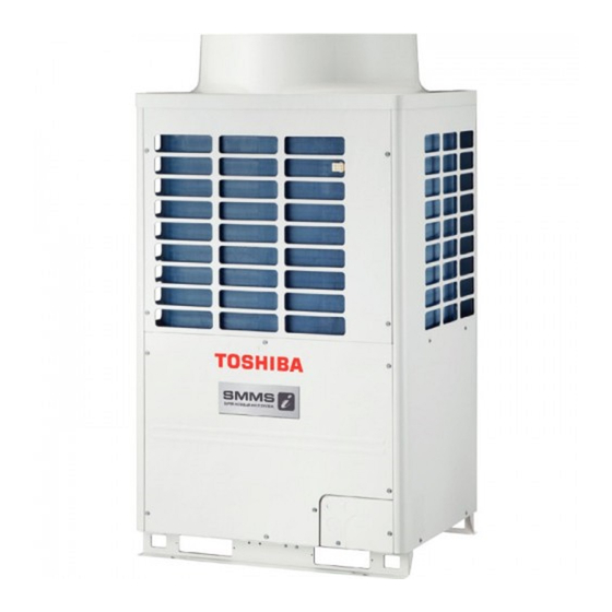
MMY-MAP1404T8(Z)(ZG)-E a person who has been trained in matters relating to electrical work on the air conditioners made by Toshiba Carrier Corporation or, alternatively, he or she has been instructed in such matters by an individual or individuals who have MMY-MAP1604HT8(Z)(ZG)-E been trained and is thus thoroughly acquainted with the knowledge related to this work.
Installation Manual Installation Manual Super modular Multi System Super modular Multi System ACCESSORY PARTS Work undertaken Protective gear worn Protective gloves All types of work ‘Safety’ working clothing Part name Q’ty Shape Usage Gloves to provide protection for electricians and from heat Electrical-related Insulating shoes Installation Manual...
Installation Manual Installation Manual Super modular Multi System Super modular Multi System PRECAUTIONS FOR SAFETY Refrigerant piping • Install the refrigerant pipe securely during the installation work before operating the air conditioner. If the compressor is operated with the valve open and without refrigerant pipe, the compressor sucks air and the refrigeration cycles is over pressurized, which may cause a injury.
Installation Manual Installation Manual Super modular Multi System Super modular Multi System INSTALLATION OF NEW REFRIGERANT Relocation • Only a qualified installer(*1) or qualified service person(*1) is allowed to relocate the air conditioner. It is dangerous for the AIR CONDITIONER air conditioner to be relocated by an unqualified individual since a fire, electric shocks, injury, water leakage, noise and/or vibration may result.
Installation Manual Installation Manual Super modular Multi System Super modular Multi System SELECTION OF INSTALLATION PLACE Installation space Leave space necessary for running, installation and servicing. WARNING Air outlet • Install the air conditioner in a place able to bear its weight. If strength is insufficient, the unit may fall down resulting in injury.
Installation Manual Installation Manual Super modular Multi System Super modular Multi System CARRYING IN THE OUTDOOR UNIT Cooperating outdoor unit Model name (Standard type) Unit 1 Unit 2 Unit 3 MMY-AP3214* MMY-MAP1604* MMY-MAP1604* CAUTION MMY-AP3414* MMY-MAP1204* MMY-MAP1204* MMY-MAP1004* MMY-AP3614* MMY-MAP1204* MMY-MAP1204* MMY-MAP1204* Handle the outdoor unit carefully, observing the following items.
Installation Manual Installation Manual Super modular Multi System Super modular Multi System INSTALLATION OF THE OUTDOOR UNIT • Anchor bolt positions are as shown below: 310 or 310 or Continuous hole more more (15 x 20 long hole) WARNING • Be sure to install the outdoor unit in a place able to bear its weight. If strength is insufficient, the unit may fall down resulting in human injury.
Installation Manual Installation Manual Super modular Multi System Super modular Multi System REFRIGERANT PIPING 5. Be careful of the connecting arrangement of the header unit and follower units. Set the outdoor units in order of capacity from the one with the largest capacity. (A (Header unit) ≥ B ≥ C ≥ D) •...
Page 10
Installation Manual Installation Manual Super modular Multi System Super modular Multi System Pipe REQUIREMENT MMY- Draw-out forward Draw-out downward diameter • For a welding work of the refrigerant pipes, be sure to use nitrogen gas in order to prevent oxidation of the inside Cut the L-shaped pipe at the horizontal straight Cut the L-shaped pipe at the vertical straight of the pipes;...
Page 11
Installation Manual Installation Manual Super modular Multi System Super modular Multi System (Unit: mm) Table 2 Connected section Capacity code Outdoor unit model name No. of indoor units External size Internal size (Standard model) Standard outer dia. Equivalent to HP Equivalent to capacity Min.
Page 12
Installation Manual Installation Manual Super modular Multi System Super modular Multi System Piping parts Name Selection of pipe size Remarks Piping parts Name Selection of pipe size Remarks Connecting pipe size of indoor unit Connecting pipe size of outdoor unit Liquid Model Gas side...
Page 13
Installation Manual Installation Manual Super modular Multi System Super modular Multi System Allowable length of refrigerant pipes and allowable height Header Follower Follower Follower unit A unit B unit C unit D difference between units Outdoor unit Follower unit D Outdoor unit Height (1) Outdoor unit connecting pipes...
Page 14
Installation Manual Installation Manual Super modular Multi System Super modular Multi System ◆ Cautions for installation WARNING • Set the outdoor unit first connected to the bridging pipe to the indoor units as the header unit. Never use oxygen, flammable gases, or noxious gases in an airtight test. •...
Installation Manual Installation Manual Super modular Multi System Super modular Multi System Air purge Adding refrigerant • Be sure to perform vacuuming from both liquid and gas sides. After finishing vacuuming, exchange the vacuum pump with a refrigerant canister and start additional charging of refrigerant.
Page 16
Installation Manual Installation Manual Super modular Multi System Super modular Multi System C (Corrective amount Ball valve Combined HP (HP) Combined outdoor units (HP) of refrigerant) (kg) Using a minus screwdriver, turn it counterclockwise by 90° until it hits the stopper. (Full open) -4.0 10HP...
Installation Manual Installation Manual Super modular Multi System Super modular Multi System ELECTRIC WIRING Power Supply MOCP Model Phase and frequency Nominal Voltage MMY-MAP3414* 82.5 CAUTION MMY-MAP3614* 85.5 MMY-MAP3814* 90.5 Be sure to attach an earth leakage breaker. MMY-MAP4014* 93.5 3N~ 50Hz 380-400-415V If no earth leakage breaker is attached, an electric shock may be caused.
Page 18
Installation Manual Installation Manual Super modular Multi System Super modular Multi System ◆ Restriction of control wiring Specifications for communication wiring Be sure to keep the rule of below tables about size and length of control wiring. ◆ Design of control wiring Central control device...
Page 19
Installation Manual Installation Manual Super modular Multi System Super modular Multi System ◆ Group Operation through a Remote Controller ◆ Power cable connection Group operation of multiple indoor units (8 units) through a single remote controller switch 1. Insert the power cable and earth line through the cutout on the side of the electric parts box and connect the power cable to the power terminal block and the earth line to the earth screw.
Installation Manual Installation Manual Super modular Multi System Super modular Multi System ADDRESS SETTING ◆ Address setting procedure 1 Turn on the indoor and outdoor units. (Indoor units first) On this unit, it is required to set the addresses of the indoor units before starting air conditioning. About one minute after turning the power on, confirm that the 7-segment display on the interface Set the addresses following the steps below.
Page 21
Installation Manual Installation Manual Super modular Multi System Super modular Multi System ◆ Address setting procedure 2 SW13 SW14 System address Set a system address for each system using SW 13 and 14 on the interface P.C. board on the header outdoor unit of each system.
Page 22
Installation Manual Installation Manual Super modular Multi System Super modular Multi System Connect the relay connectors between the [U1U2] and [U3U4] terminals of the header outdoor Switch setting (setting example when controlling two or more refrigerant lines centrally) unit of each refrigerant line. Outdoor units (setting manually) *The items in black cells must be set manually.
Page 23
Installation Manual Installation Manual Super modular Multi System Super modular Multi System Confirmation of indoor (OK when display goes on.) CAUTION <Indoor address> address and the main unit Relay connector connection Using the setup temp. buttons, position on the remote Never connect relay connectors between the [U1U2] and [U3U4] terminals before completing address setting of all the set to the item code.
Page 24
Installation Manual Installation Manual Super modular Multi System Super modular Multi System When you want to know position of the ▼ To confirm all the unit numbers from an Change of indoor address ▼ To change all the indoor addresses from an arbitrary wired remote controller;...
Page 25
Installation Manual Installation Manual Super modular Multi System Super modular Multi System Central control device CODE No. DATA SETTING UNIT No. R.C. TEMP. ON / OFF Follower unit Header unit Follower unit Header unit Header unit Center unit Center unit Center unit Center unit U3 U4...
Installation Manual Installation Manual Super modular Multi System Super modular Multi System TEST OPERATION After the test operation has finished, push Set the rotary switch SW01 on the interface ON / OFF button to stop the operation. P.C. board of the header unit to [16], and (Display is same to that in procedure 1.) match SW02 and SW03 to the address of the indoor unit to be operated with test mode.
Installation Manual Installation Manual Super modular Multi System Super modular Multi System TROUBLESHOOTING <Collective test operation> ▼ Start operation In addition to the check code on the remote controller of the indoor unit, a trouble of the outdoor unit can be Set the rotary switches of interface P.C.
Page 28
Installation Manual Installation Manual Super modular Multi System Super modular Multi System Check code Check code Indication on 7-segment display on the outdoor unit Check code name Indication on 7-segment display on the outdoor unit Check code name Auxiliary code Auxiliary code 01: Compressor 1 01: TK1 oil circuit error...
Manufacturer: Toshiba Carrier Corporation 336 Tadehara, Fuji-shi, Shizuoka-ken 416-8521 JAPAN Authorized Nick Ball Representative/ Toshiba EMEA Engineering Director TCF holder: Toshiba Carrier UK Ltd. Porsham Close, Belliver Industrial Estate, PLYMOUTH, Devon, PL6 7DB. United Kingdom Hereby declares that the machinery described below:...
Page 30
WARNINGS ON REFRIGERANT LEAKAGE Check of Concentration Limit Important The room in which the air conditioner is to be installed NOTE 2 : requires a design that in the event of refrigerant gas The standards for minimum room volume are as leaking out, its concentration will not exceed a set limit.
This manual is also suitable for:
Mmy-map0804ht8-eMmy-map0804t8-eMmy-map1004t8-eMmy-map1204t8-eMmy-map1404t8-eMmy-map1604t8-e...
Show all
Need help?
Do you have a question about the MMY-MAP1004HT8-E and is the answer not in the manual?
Questions and answers