
Related Manuals for MEN Mikro Elektronik A14C – 6U VME64 MPC8540

Summary of Contents for MEN Mikro Elektronik A14C – 6U VME64 MPC8540
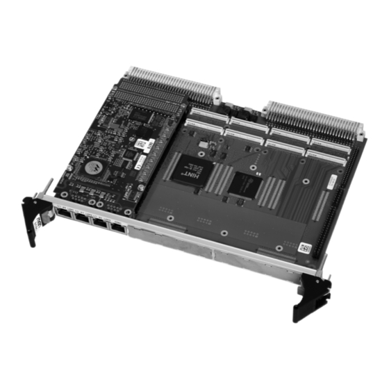
- Page 1 20A014-00 E2 – 2007-08-16 A14C – 6U VME64 MPC8540 SBC / PMC Configuration example User Manual ®...
- Page 2 The A14C comes with MENMON™ support. This firmware/BIOS can be used for bootstrapping operating systems (from disk, Flash or network), for hardware testing, or for debugging applications without running any operating system. MEN Mikro Elektronik GmbH 20A014-00 E2 – 2007-08-16...
-
Page 3: Technical Data
- Two on-board LEDs to signal LAN Link and Activity • One RS232 UART (COM1) - One RJ45 connector at front panel - Data rates up to 115.2kbits/s - 16-byte transmit/receive buffer - Handshake lines: CTS, RTS MEN Mikro Elektronik GmbH 20A014-00 E2 – 2007-08-16... - Page 4 • The FPGA offers the possibility to add customized I/O functionality. See FPGA. Mezzanine Slots • Two PMC slots - Compliant with PMC standard IEEE 1386.1 - Up to 64-bit/64-MHz, 3.3V V(I/O) - PMC I/O module (PIM) support through J4 MEN Mikro Elektronik GmbH 20A014-00 E2 – 2007-08-16...
- Page 5 - -12V (-5%/+5%), only provided for PMCs that need 12V • MTBF: 92,800h @ 40°C (derived from MIL-HDBK-217F) Mechanical Specifications • Dimensions: standard double Eurocard, 233.3mm x 160mm • Weight (without PMC modules): 450g MEN Mikro Elektronik GmbH 20A014-00 E2 – 2007-08-16...
- Page 6 IEC1000-4-4 (burst) with regard to CE conformity BIOS • MENMON™ Software Support • VxWorks® • Linux (ELinOS) • QNX® • For more information on supported operating system versions and drivers see online data sheet. MEN Mikro Elektronik GmbH 20A014-00 E2 – 2007-08-16...
-
Page 7: Block Diagram
R Rear I/O MPC8540 Ethernet On Board 1000Base-T Option Ethernet 100Base-T RS232 COM1 FPGA COM10 GPIO SDRAM NAND Additional Flash Quad UART COM20..23 PMC 1 PCI-toPCI Bridge PMC 0 SSRAM PCI-to-VMEbus Bridge MEN Mikro Elektronik GmbH 20A014-00 E2 – 2007-08-16... -
Page 8: Configuration Options
• 2 PMC • 3 PC-MIP® Operation Temperature • 0..+60°C Please note that some of these options may only be available for large volumes. Please ask our sales staff for more information. MEN Mikro Elektronik GmbH 20A014-00 E2 – 2007-08-16... - Page 9 - Integrated VHDL and Verilog HDL synthesis and support for third-party syn- thesis software - SOPC Builder system generation software - Place-and-route, verification, and programming » Altera® Quartus® II Web Edition FPGA design tool MEN Mikro Elektronik GmbH 20A014-00 E2 – 2007-08-16...
- Page 10 • Store the board only in its original ESD-protected packaging. Retain the original packaging in case you need to return the board to MEN for repair. MEN Mikro Elektronik GmbH 20A014-00 E2 – 2007-08-16...
-
Page 11: About This Document
"in" meaning "to the board or component", "out" meaning "coming from it". Vertical lines on the outer margin signal technical changes to the previous edition of the document. MEN Mikro Elektronik GmbH 20A014-00 E2 – 2007-08-16... -
Page 12: Legal Information
MEN was negligent regarding the design or manufacture of the part. Unless agreed otherwise, the products of MEN Mikro Elektronik are not suited for use in nuclear reactors and for application in medical appliances used for therapeutical purposes. Application of MEN products in such plants is only possible after the user has precisely specified the operation environment and after MEN Mikro Elektronik has consequently adapted and released the product. -
Page 13: Table Of Contents
2.13 PMC Slots ..........46 2.13.1 Installing a PMC Mezzanine Module ....47 MEN Mikro Elektronik GmbH 20A014-00 E2 – 2007-08-16... - Page 14 IDE/NAND Flash ....... . 102 MEN Mikro Elektronik GmbH 20A014-00 E2 – 2007-08-16...
- Page 15 Number ..........119 MEN Mikro Elektronik GmbH...
- Page 16 Figure 10. MENMON – State diagram, Main State ..... . . 95 Figure 11. Label giving the board’s article number, revision and serial number 119 MEN Mikro Elektronik GmbH 20A014-00 E2 – 2007-08-16...
- Page 17 Table 34. MENMON – Program update files and locations ....97 Table 35. MENMON – Diagnostic tests: Ethernet......99 MEN Mikro Elektronik GmbH 20A014-00 E2 – 2007-08-16...
- Page 18 Table 60. PCI devices on Bus 0 ........117 MEN Mikro Elektronik GmbH...
-
Page 19: Getting Started
Figure 1. Map of the Board – front view Seond Front Alternative COM20..23 COM20..23 A14c Standard (via 40-pin via 10-pin connector) connectors COM20 COM21 COM22 COM23 PMC 1 COM23 COM22 COM21 PMC 0 COM20 MEN Mikro Elektronik GmbH 20A014-00 E2 – 2007-08-16... -
Page 20: Figure 2. Map Of The Board - Top View
Plug-on Module Heat Sink (facing in) LAN2 LAN3 SO-DIMM COM1 SA-Adapter COM23 PMC1 SA-Adapter COM22 SA-Adapter COM21 PMC0 Hard disk on adapter card SA-Adapter COM20 fuse Quad UART COM 20..23 IDE Interface MEN Mikro Elektronik GmbH 20A014-00 E2 – 2007-08-16... -
Page 21: Configuring The Hardware
Chapter 2.7 IDE Interface on page 28 for details on the IDE interface. PMC modules Refer to Chapter 2.13.1 Installing a PMC Mezzanine Module on page 47 for a detailed installation description. MEN Mikro Elektronik GmbH 20A014-00 E2 – 2007-08-16... -
Page 22: Integrating The Board Into A System
- No parity Power-up the system. The terminal displays a message similar to the following: ___________________ Secondary MENMON for MEN EM3 Family 1.3 _________________ (c) 2005 - 2005 MEN Mikro Elektronik GmbH Nuremberg MENMON 2nd Edition, Created Nov 18 2005 15:57:50... -
Page 23: Installing Operating System Software
By standard, no operating system is installed on the board. Please refer to the operating system installation documentation on how to install the software! You can find any software available on MEN’s website. MEN Mikro Elektronik GmbH 20A014-00 E2 – 2007-08-16... -
Page 24: Functional Description
A control flag indicates a back-up power fail condition. In this case the contents of the RTC cannot be expected to be valid. A message will be displayed on the MENMON console in this case. MEN Mikro Elektronik GmbH 20A014-00 E2 – 2007-08-16... -
Page 25: Powerpc Cpu
Note: MEN gives no warranty on functionality and reliability of the A14C if you use any other heat sink than that supplied by MEN. Please contact either MEN directly or your local MEN sales office! MEN Mikro Elektronik GmbH 20A014-00 E2 – 2007-08-16... -
Page 26: Bus Structure
The local processor can thus freely access the VMEbus (master). For communication in multiprocess applications, the bridge has a fast communication memory of 1 MB size. This memory can be accessed both from the local processor and from the VMEbus (slave). MEN Mikro Elektronik GmbH 20A014-00 E2 – 2007-08-16... -
Page 27: Memory
By standard, the board is supplied with 16 MB additional SDRAM. It is controlled by the FPGA and can be used for graphics or other functions. 2.6.6 EEPROM The board has a 4-kbit serial EEPROM for factory data, MENMON parameters, and for the VxWorks bootline. MEN Mikro Elektronik GmbH 20A014-00 E2 – 2007-08-16... -
Page 28: Ide Interface
Table 1. Pin assignment of 44-pin IDE plug connector IDE_RST# IDE_D[7] IDE_D[8] IDE_D[6] IDE_D[9] IDE_D[5] IDE_D[10] IDE_D[4] IDE_D[11] IDE_D[3] IDE_D[12] IDE_D[2] IDE_D[13] IDE_D[1] IDE_D[14] IDE_D[0] IDE_D[15] IDE_WR# IDE_RD# IDE_RDY IDE_IRQ IDE_A[1] IDE_A[0] IDE_A[2] IDE_CS1# IDE_CS3# MEN Mikro Elektronik GmbH 20A014-00 E2 – 2007-08-16... -
Page 29: Figure 3. Position Of Fuse For Ide Protection
The fuse is located on the top side of A14C. Figure 3. Position of fuse for IDE protection SA-Adapter COM21 Hard disk on adapter card SA-Adapter COM20 fuse Quad UART COM 20..23 IDE Interface MEN Mikro Elektronik GmbH 20A014-00 E2 – 2007-08-16... -
Page 30: Installing A Hard Disk
Make sure to match the pins correctly. Fasten the hard disk to the adapter card at the bottom side of the adapter using the four cross-recess screws (M3x5) and suitable nuts provided with the adapter. MEN Mikro Elektronik GmbH 20A014-00 E2 – 2007-08-16... - Page 31 Fasten the hard-disk adapter card to A14C at the bottom side of the A14C using the four recess screws (M2.5x4) and suitable nuts provided with the adapter. Reinsert the board into your system. MEN Mikro Elektronik GmbH 20A014-00 E2 – 2007-08-16...
-
Page 32: Ethernet Interfaces
Lights up whenever there is transmit or receive activity MDX[1]+ MDX[2]+ MDX[2]- MDX[1]- Lights up as soon as the link is established MDX[3]+ MDX[3]- Note: Please note that LAN3 supports only 10/100Base-T! MEN Mikro Elektronik GmbH 20A014-00 E2 – 2007-08-16... -
Page 33: Table 5. Pin Assignment Of 9-Pin D-Sub 10Base-T/100Base-Tx Plug Connector
(LAN1 and LAN2) LAN1_TX+ LAN1_TX- LAN2_TX+ LAN2_TX- LAN2_RX- LAN2_RX+ LAN1_RX- LAN1_RX+ Table 6. Pin assignment of 9-pin D-Sub 10Base-T/100Base-TX plug connector (LAN3 and COM1) LAN3_TX+ LAN3_TX- COM1_RXD COM1_RTS# COM1_TXD COM1_CTS# LAN3_RX+ LAN3_RX- MEN Mikro Elektronik GmbH 20A014-00 E2 – 2007-08-16... -
Page 34: General
Because many companies already use CAT-5 cabling, 1000Base-T can be easily implemented. Other 1000Base-T benefits include compatibility with existing network protocols (i.e. IP, IPX, AppleTalk), existing applications, Network Operating Systems, network management platforms and applications. MEN Mikro Elektronik GmbH 20A014-00 E2 – 2007-08-16... -
Page 35: Uart Com1 Interface
Connection via RJ45 Connector Connector types: • Modular 8/8-pin mounting jack according to FCC68 • Mating connector: Modular 8/8-pin plug according to FCC68 Table 8. Pin assignment of 8-pin RJ45 UART connector (COM1) CTS# RTS# MEN Mikro Elektronik GmbH 20A014-00 E2 – 2007-08-16... -
Page 36: Table 9. Pin Assignment Of 9-Pin D-Sub Com1/Lan3 Plug Connector
9-pin D-Sub receptacle according to DIN41652/MIL-C-24308, available for rib- bon cable (insulation piercing connection), hand-soldering connection or crimp connection Table 9. Pin assignment of 9-pin D-Sub COM1/LAN3 plug connector LAN3_TX+ LAN3_TX- COM1_RXD COM1_RTS# COM1_TXD COM1_CTS# LAN3_RX+ LAN3_RX- MEN Mikro Elektronik GmbH 20A014-00 E2 – 2007-08-16... -
Page 37: Uart Com10 Interface
PMC I/O signals, since this may cause damage to the CPU board. See Chapter 2.16.16.1 Rear I/O using VMEbus P2 on page 77 for more details and for pin assignments of P2. MEN Mikro Elektronik GmbH 20A014-00 E2 – 2007-08-16... -
Page 38: Uart Com20..Com23 Interfaces
+5V power supply; current-limited to 1.5A by a fuse with 10-pin connectors CTS# Clear to send DCD# Data carrier detect DSR# Data set ready DTR# Data terminal ready Digital ground Ring indicator RTS# Request to send Receive data Transmit data MEN Mikro Elektronik GmbH 20A014-00 E2 – 2007-08-16... -
Page 39: Connection Via 40-Pin Connector
COM23 DSR23# CTS23# DCD23# RI23# TXD22 RXD22 DTR22# RTS22# COM22 DSR22# CTS22# DCD22# RI22# TXD21 RXD21 DTR21# RTS21# COM21 DSR21# CTS21# DCD21# RI21# TXD20 RXD20 DTR20# RTS20# COM20 DSR20# CTS20# DCD20# RI20# MEN Mikro Elektronik GmbH 20A014-00 E2 – 2007-08-16... - Page 40 SA-Adapter. Remove the blind connector from the additional front panel, if you need a slot that is covered: Loosen the two screws at the front of the panel. COM20 COM21 COM22 COM23 MEN Mikro Elektronik GmbH 20A014-00 E2 – 2007-08-16...
- Page 41 Use the SA-Adapter’s front panel screws to fasten the adapter at the additional front panel. You can now reinsert the board and the additional front panel into your system. Make sure to fasten the SA-Adapter front panel appropriately in your enclo- sure! MEN Mikro Elektronik GmbH 20A014-00 E2 – 2007-08-16...
-
Page 42: Connection Via 10-Pin Sa-Adapter Connectors
Loosen the two screws at the front of the panel. COM23 COM22 COM21 COM20 The SA-Adapter is plugged on the A14C with the component sides of the PCBs facing each other. MEN Mikro Elektronik GmbH 20A014-00 E2 – 2007-08-16... -
Page 43: Figure 4. Installing Sa-Adapters On A14C Directly
Screw the SA-Adapter tightly to the A14C using the front-panel and standoff screws removed before. Figure 4. Installing SA-Adapters on A14C directly SA-Adapter Mounting 10-pin connectors standoff CPU board 2 M3x6 pan-head screws according to DIN85 with washers MEN Mikro Elektronik GmbH 20A014-00 E2 – 2007-08-16... -
Page 44: Figure 5. Position Of Fuse For Com20..Com23 Protection
• Size: 1206 • MEN part number: 5675-0001 The fuses are located on the bottom side of A14C. Figure 5. Position of fuse for COM20..COM23 protection COM23 fuse COM22 fuse COM21 fuse COM20 fuse MEN Mikro Elektronik GmbH 20A014-00 E2 – 2007-08-16... -
Page 45: Gpio
PMC I/O signals, since this may cause damage to the CPU board. See Chapter 2.16.16.1 Rear I/O using VMEbus P2 on page 77 for more details and for pin assignments of P2. MEN Mikro Elektronik GmbH 20A014-00 E2 – 2007-08-16... -
Page 46: Pmc Slots
P2. Connector types: • 64-pin, 1-mm pitch board-to-board receptacle according to IEEE 1386 • Mating connector: 64-pin, 1-mm pitch board-to-board plug according to IEEE 1386 MEN Mikro Elektronik GmbH 20A014-00 E2 – 2007-08-16... -
Page 47: Installing A Pmc Mezzanine Module
M2.5x6. Figure 6. Installing a PMC mezzanine module PMC module Mounting standoff 64-pin connectors CPU board 2 M2.5x6 oval-head 2 M2.5x6 oval- head cross- cross-recessed recessed screws screws MEN Mikro Elektronik GmbH 20A014-00 E2 – 2007-08-16... -
Page 48: Board-To-Board I/O Connector
Chapter 2.16.16.1 Rear I/O using VMEbus P2 on page 77 for more details and for pin assignments of P2. Connector types: • 4-row, 120-pin PCI-104 receptacle connector, 2mm pitch • Mating connector: 4-row, 120-pin PCI-104 plug connector, 2mm pitch MEN Mikro Elektronik GmbH 20A014-00 E2 – 2007-08-16... -
Page 49: Table 14. Pin Assignment Of I/O Connector J2 - Factory Standard Fpga
GPIO_1.7 IDE_RDY +3.3V GPIO_2.1 GPIO_3.4 GPIO_2.0 +3.3V GPIO_2.2 GPIO_2.3 IDE_IRQ GPIO_3.5 GPIO_2.5 PBRST# (GPIO_2.4) IDE_A1 GPIO_2.6 GPIO_2.7 IDE_A0 GPIO_3.6 GPIO_4.1 IDE_A2 GPIO_4.0 IDE_CS1# GPIO_4.2 GPIO_4.3 GPIO_3.7 IDE_CS3# GPIO_4.5 GPIO_4.4 +3.3V_STBY GPIO_4.6 GPIO_4.7 MEN Mikro Elektronik GmbH 20A014-00 E2 – 2007-08-16... -
Page 50: Table 15. Signal Mnemonics Of I/O Connector J2 - Factory Standard Fpga
COM10 Data set ready DTR10# COM10 Data terminal ready RI10 COM10 Ring indicator RTS10# COM10 request to send RXD10 COM10 receive data TXD10 COM10 transmit data Other GPIO_x in/out GPIO lines PBRST# Push button reset MEN Mikro Elektronik GmbH 20A014-00 E2 – 2007-08-16... -
Page 51: Reset Button
Functional Description 2.15 Reset Button A reset button is integrated in the A14C’s front panel handle. Figure 7. Position of reset button Reset button MEN Mikro Elektronik GmbH 20A014-00 E2 – 2007-08-16... -
Page 52: Vmebus Interface
• DMA controller with scatter gather DMA (A32/D64) • Mailbox functionality • Location monitor A16, A24, A32 • Dual-ported system register • Access to 1 MB dual-ported fast SRAM, 66-MHz or access to PCI space MEN Mikro Elektronik GmbH 20A014-00 E2 – 2007-08-16... -
Page 53: Pci Configuration Space Registers
0x28 Card Bus CIS Pointer 0x2C Subsystem ID (0x7A30) Subsystem Vendor ID (0x3032) 0x30 Expansion ROM Base Address Register 0x34 Reserved 0x38 Reserved 0x3C Maximum Minimum Grant Interrupt Pin Interrupt Line Latency MEN Mikro Elektronik GmbH 20A014-00 E2 – 2007-08-16... -
Page 54: Runtime Registers
MAILBOX_2 – Mailbox Data Register (r/w) 0x FF80C MAILBOX_3 – Mailbox Data Register (r/w) 0x FF900..FF90C DMA_BD#1 – DMA Buffer Descriptor (r/w) 0x FF910..FF91C DMA_BD#2 – DMA Buffer Descriptor (r/w) .. 0x 0FF0..0FFC Further Buffer Descriptors MEN Mikro Elektronik GmbH 20A014-00 E2 – 2007-08-16... -
Page 55: Vmebus Master Mapping
Table 22. VMEbus interface BAR4 BAR4 Size Function 0x 0000 0000 .. 0x 00FF FFFC 16MB VME A24 D32 (standard) space 0x 0100 0000 .. 0x 01FF FFFC 16MB VME A24 D32 (standard) space swapped MEN Mikro Elektronik GmbH 20A014-00 E2 – 2007-08-16... -
Page 56: Vme Slave Mapping
Slave Control Registers for A24 or A32 (in A32 mode the SRAM is mirrored!). The SRAM has a size of 1 MB. It is accessible via block and standard transfers (user and supervisor space). MEN Mikro Elektronik GmbH 20A014-00 E2 – 2007-08-16... -
Page 57: Slot-1 Function
Reset VMEbus; generates SYSRES# on the VMEbus SYSRES# not active SYSRES# active SYSCON System controller status (depends on slot 1 auto-detection after reset). May be overridden by software. Slot 1 function disabled Slot 1 function enabled MEN Mikro Elektronik GmbH 20A014-00 E2 – 2007-08-16... -
Page 58: Vmebus Master Interface
The following master/slave RMW accesses are allowed: • Byte or word access in D16 mode • Byte, word or long access in D32 mode Note: During RMW cycles all interrupts on the host CPU should be masked. MEN Mikro Elektronik GmbH 20A014-00 E2 – 2007-08-16... -
Page 59: Table 24. Vmebus Interface Valid Combinations For Byte Enables Supported By Pci
D7..D0 Second: D15..D8 D7..D0 First: D31..D24 D7..D0 Second: D7..D0 D15..D8 First: D23..D16 D15..D8 Second: D15..D8 D7..D0 First: D23..D16 D15..D8 Second: D7..D0 D15..D8 D15..D8 D7..D0 First: D23..D16 D15..D8 D31..D24 D7..D0 Second: D15..D8 D7..D0 MEN Mikro Elektronik GmbH 20A014-00 E2 – 2007-08-16... - Page 60 D55..D48 D15..D8 D63..D56 D7..D0 PCI address bits A1 and A0 are only examined during I/O reads and writes. During memory reads and writes (as is the case here) these are always 0. MEN Mikro Elektronik GmbH 20A014-00 E2 – 2007-08-16...
-
Page 61: Table 25. Vmebus Master Address Modifier Codes
Read-Modify-Write operations to the VMEbus can be done via bit RMW in the MSTR – Master Control Register (0x0010) (read/write). Only byte and word accesses are allowed, with word accesses being made to even addresses. VME-to-SRAM Operations Supported. MEN Mikro Elektronik GmbH 20A014-00 E2 – 2007-08-16... -
Page 62: Vmebus Slave Interface
SLBASE16 Slave's Base Address. Specifies the lowest address in the VME address range that will be decoded. Since only A[15:12] are monitored, the smallest possible address space is 4 KB. Default: 0000 MEN Mikro Elektronik GmbH 20A014-00 E2 – 2007-08-16... - Page 63 SLBASE32 Slave's Base Address. Specifies the lowest address in the VME address range that will be decoded. Since only A[31:20] are monitored, the smallest possible address space is 1 MB. Default: 000000000000 MEN Mikro Elektronik GmbH 20A014-00 E2 – 2007-08-16...
- Page 64 SLBASE24_PCI Slave's Base Address for PCI access. Specifies the lowest address in the VME address range that will be decoded. Since only A[23:16] are monitored, the smallest possible address space is 64 KB. Default: 00000000 MEN Mikro Elektronik GmbH 20A014-00 E2 – 2007-08-16...
- Page 65 PCI_OFFSET 4-kbyte aligned offset address on PCI bus for VME-to-PCI accesses. The PCI space is accessible via A24 and A32 access on the VMEbus. To do this, the SLV24_PCI or SLV32_PCI control registers must be set. MEN Mikro Elektronik GmbH 20A014-00 E2 – 2007-08-16...
-
Page 66: Table 26. Vmebus Slave Address Modifier Codes
H A32 supervisory data access 0x0C H H L A32 supervisory 64-bit block transfer (MBLT) 0x0B H H A32 non-privileged block transfer (BLT) 0x09 H A32 non-privileged data access 0x08 A32 non-privileged 64-bit block transfer (MBLT) MEN Mikro Elektronik GmbH 20A014-00 E2 – 2007-08-16... -
Page 67: Vmebus Requester
Both register schemes are implemented as fair requester. Settings are made in the MSTR – Master Control Register (0x0010) (read/write). Chapter 2.16.7 VMEbus Master Interface on page Unused daisy-chain lines are passed by (BG0IN#/OUT#, BG1IN#/OUT#, BG2IN#/ OUT#). MEN Mikro Elektronik GmbH 20A014-00 E2 – 2007-08-16... -
Page 68: Vmebus Interrupt Handler
In order to read the interrupt STATUS/ID from the interrupter, the CPU must generate a read cycle to the IACK memory area by setting the last significant address bits A[3..1] to the corresponding interrupt level (e. g. for IRQ5# set A[3:1] to [101]). MEN Mikro Elektronik GmbH 20A014-00 E2 – 2007-08-16... -
Page 69: Vmebus Interrupter
INTID – VME Interrupt STATUS/ID Register (0x0004) (read/write) 7..0 INT_ID In this Register, the STATUS/ID of the internal interrupter is set. INT_ID The STATUS/ID of the interrupt that the external handler reads during the IACK cycle. Default: 0x00 MEN Mikro Elektronik GmbH 20A014-00 E2 – 2007-08-16... -
Page 70: A32 Address Mode
ADDR31..ADDR29 Upper 3 address bits for A32 access. These bits will be combined with the address bits ADDR28..ADDR2 while an A32 access on the VMEbus is performed, in order to address the entire A32 space. MEN Mikro Elektronik GmbH 20A014-00 E2 – 2007-08-16... -
Page 71: Mailbox
Interrupt Request Register (0x0024) (read/write), if the interrupt is enabled in the MAIL_IRQE – Mailbox Interrupt Enable Register (0x0020) (read/write). This data register can be used to transmit a status or ID. MEN Mikro Elektronik GmbH 20A014-00 E2 – 2007-08-16... -
Page 72: Location Monitor
A16 - Address bits [15:10] on VMEbus will be compared with LOCADDR_x [15:10] 1 1 = A24 - Address bits [23:10] on VMEbus will be compared with LOCADDR_x [23:10] LOC_IRQE_x 0 = Monitor interrupt request is disabled Monitor interrupt request is enabled MEN Mikro Elektronik GmbH 20A014-00 E2 – 2007-08-16... - Page 73 ADDR[31:0] ADDR[31:0] Compare address for location monitor The desired address bits depend on LOC_AM_1: LOC_AM_1 = 0 0: LOCADDR_1 [31:10] LOC_AM_1 = 1 0: LOCADDR_1 [15:10] LOC_AM_1 = 1 1: LOCADDR_1 [23:10] MEN Mikro Elektronik GmbH 20A014-00 E2 – 2007-08-16...
-
Page 74: Dma Controller
DMA IRQ is disabled DMA IRQ is enabled DMA_EN DMA transaction is stopped (or will be stopped if set to 0) DMA transaction is enabled (will be set to 0 when done) MEN Mikro Elektronik GmbH 20A014-00 E2 – 2007-08-16... - Page 75 A32 D64 swapped INC_SOUR Increment source address during operation Keep source address INC_DEST Increment destination address during operation Keep destination address DMA_NULL End is not yet reached End of buffer descriptor list is reached MEN Mikro Elektronik GmbH 20A014-00 E2 – 2007-08-16...
-
Page 76: Connection
BG3IN# SYSFAIL# GA0# BG3OUT# BERR# GA1# DS1# BR0# SYSRESET# DS0# BR1# LWORD# GA2# WRITE# BR2# BR3# GA3# DTACK# GA4# IACK# IACKIN# IACKOUT# IRQ7# IRQ6# IRQ5# IRQ4# IRQ3# IRQ2# IRQ1# -12V VSTBY +12V MEN Mikro Elektronik GmbH 20A014-00 E2 – 2007-08-16... - Page 77 You can switch FPGA signals to the P2 connector through an MEN software tool, Chapter Switching FPGA and PMC Signals on Connector P2 through Software on page The following tables give the detailed pin assignments for P2. MEN Mikro Elektronik GmbH 20A014-00 E2 – 2007-08-16...
-
Page 78: Table 28. Pin Assignment Of Vmebus Rear I/O Connector P2 - Pmc Signals
PMC0_J4.34 PMC0_J4.33 PMC0_J4.36 PMC0_J4.35 PMC0_J4.38 PMC0_J4.37 PMC0_J4.40 PMC0_J4.39 PMC0_J4.42 PMC0_J4.41 PMC0_J4.44 PMC0_J4.43 PMC0_J4.46 PMC0_J4.45 PMC0_J4.48 PMC0_J4.47 PMC0_J4.50 PMC0_J4.49 PMC0_J4.52 PMC0_J4.51 PMC0_J4.54 PMC0_J4.53 PMC0_J4.56 PMC0_J4.55 PMC0_J4.58 PMC0_J4.57 PMC0_J4.60 PMC0_J4.59 PMC0_J4.62 PMC0_J4.61 PMC0_J4.64 PMC0_J4.63 MEN Mikro Elektronik GmbH 20A014-00 E2 – 2007-08-16... -
Page 79: Table 29. Signal Mnemonics Of Vmebus Rear I/O Connector P2 - Pmc 0
Direction Function Power +5V power supply Digital ground VME64 A[31:24] VME64 address lines D[31:16] in/out VME64 data lines PMC 0 PMC0_J4.xx in/out Signal xx from PMC 0 rear I/O con- nector J4 MEN Mikro Elektronik GmbH 20A014-00 E2 – 2007-08-16... - Page 80 78. FPGA signals are only available if switched through to P2. See page Some of the PMC signals and FPGA I/O signals overlap on the P2 connector. Do not use overlapping interfaces simultaneously! MEN Mikro Elektronik GmbH 20A014-00 E2 – 2007-08-16...
-
Page 81: Table 31. Signal Mnemonics Of Vmebus Rear I/O Connector P2 - Fpga I/O
-p 0 -x 1 Switch FPGA I/O signals to P2 fpga_load -p 0 -x 2 Switch PMC signals to P2 fpga_load -p 0 -x 3 Disable both FPGA and PMC signals on P2 MEN Mikro Elektronik GmbH 20A014-00 E2 – 2007-08-16... -
Page 82: Fpga
FPGA IP cores. Chapter 3.3 Standard Factory FPGA Configuration on page 92 describes one possible configuration of the FPGA. Please ask our sales staff for other configurations. MEN Mikro Elektronik GmbH 20A014-00 E2 – 2007-08-16... -
Page 83: System Unit
5V/3.3V can be used by the CPU to save the date and time of exception. This interrupt can be enabled or disabled by handling the System Unit Control Register (SUCR). MEN Mikro Elektronik GmbH 20A014-00 E2 – 2007-08-16... - Page 84 If the time interval exceeds without a correct write operation, the watchdog executes a system reset by forcing HRSTN to 0. Additionally bit WDEX is set in the Reset Cause Register to provide the reset cause information after system restart. MEN Mikro Elektronik GmbH 20A014-00 E2 – 2007-08-16...
-
Page 85: Address Organization
0x0098 System Unit Interrupt Request Register (SUIRQR) (r/w) 0x009C General Purpose Memory Register (GPMR) (r/w) 0x00A4..0x00FF Reserved 0x0100..0x1FFF FPGA IP cores (see detailed address map in the respective IP core user manual) MEN Mikro Elektronik GmbH 20A014-00 E2 – 2007-08-16... - Page 86 You can find an overview and descriptions of all available FPGA IP cores on MEN’s website. Chapter 3.3 Standard Factory FPGA Configuration on page 92 gives an example configuration, including a configuration table. MEN Mikro Elektronik GmbH 20A014-00 E2 – 2007-08-16...
- Page 87 1 = External reset button was activated WDEX 0 = Internal watchdog triggered correctly 1 = Internal watchdog expired (not triggered by CPU) HRSTN 0 = No HRESET occurred 1 = HRESET from an external module occurred MEN Mikro Elektronik GmbH 20A014-00 E2 – 2007-08-16...
- Page 88 0 124 s count clock This calculation leads to a user-configurable watchdog expiration time interval of: Register Value = 000000000000000bin Wdextime = 1.966 ms Register Value = 111111111111111bin Wdextime = 64.4 s MEN Mikro Elektronik GmbH 20A014-00 E2 – 2007-08-16...
- Page 89 1 = Heartbeat LED turned off SW_RST 0 = CPU reset inactive 1 = CPU reset active RCIREN 0 = Reset controller interrupt request disabled 1 = Reset controller interrupt request enabled MEN Mikro Elektronik GmbH 20A014-00 E2 – 2007-08-16...
- Page 90 1 = Power supply powerfail interrupt pending SD_INT 0 = No shutdown interrupt occurred 1 = Shutdown interrupt pending RCIRQ 0 = No reset controller interrupt request 1 = Reset controller interrupt request pending MEN Mikro Elektronik GmbH 20A014-00 E2 – 2007-08-16...
- Page 91 The register can be read from and written to by the programmer. Only power on resets the register to its initial value. 15..8 7..0 Reserved for future use GPMR 0x0000 Reset value: MEN Mikro Elektronik GmbH 20A014-00 E2 – 2007-08-16...
-
Page 92: Standard Factory Fpga Configuration
Table 33. FPGA – Factory standard configuration table for A14C IP Core Device ID Revision Offset 16Z054_SYSTEM 16Z023_IDE_NHS 16Z034_GPIO 16Z034_GPIO 16Z034_GPIO 16Z034_GPIO 16Z034_GPIO 16Z025_UART 16Z043_SDRAM 16Z053_IDEATA 16Z068_IDETGT 16Z063_NANDRAW CDEF Magic Word All values are given in Variant hexadecimal notation. Revision MEN Mikro Elektronik GmbH 20A014-00 E2 – 2007-08-16... -
Page 93: Menmon
• Update firmware or operating system. The following description only includes board-specific features. For a general description and in-depth details on MENMON 3.x, please refer to the MENMON 2nd Edition User Manual. Not supported by standard A14C! MEN Mikro Elektronik GmbH 20A014-00 E2 – 2007-08-16... -
Page 94: State Diagram
DRAM not working Check for 'D' pressed Parse SO-DIMM SPD Init DRAM Check for 'd' pressed Quick DRAM test DRAM ok Relocating MainState Full Mode FullStartup Init heap in DRAM StartupPrologue MainState MEN Mikro Elektronik GmbH 20A014-00 E2 – 2007-08-16... -
Page 95: Figure 10. Menmon - State Diagram, Main State
Leave dialog after 5 seconds Booting MenmonCli User abort or Execute mmstartup string entry/ start network servers Boot failure [mmstartup empty] do/ process command line Jump to bootstrapper No user intervention MEN Mikro Elektronik GmbH 20A014-00 E2 – 2007-08-16... -
Page 96: Interacting With Menmon
You can view and modify this string directly, using the Expert Setup Menu, option Startup string, or through the command-line command EE-MMSTARTUP. (See also MENMON 2nd Edition User Manual for further details.) MEN Mikro Elektronik GmbH 20A014-00 E2 – 2007-08-16... -
Page 97: Updating Boot Flash And Nand Flash
Copy external CF:IMAGE.FP0 -> boot flash FPGA code Copy external CF:IMAGE.FP1 -> boot flash fallback FPGA code Copy external CF:IMAGE.SMM -> boot flash sec. MENMON Copy internal CF -> external CF (1:1) MEN Mikro Elektronik GmbH 20A014-00 E2 – 2007-08-16... -
Page 98: Automatic Update Check
(see MENMON 2nd Edition User Manual). If there is no user input for 5 seconds after the menu appears, booting continues. MENMON versions < 3.4 only search for BOOTFILE. MEN Mikro Elektronik GmbH 20A014-00 E2 – 2007-08-16... -
Page 99: Diagnostic Tests
Checks: • Connection between CPU and LAN controller • Connection between LAN controller and PHY Does not check: • Connection between PHY and physical connector • Interrupt line • All LAN speeds MEN Mikro Elektronik GmbH 20A014-00 E2 – 2007-08-16... -
Page 100: Sdram And Fram
• All address lines • All data lines • Byte enable signals • Indirectly, checks clock and other control signals Does not check: • SDRAM cells • SO-DIMM SPD EEPROM • Burst mode MEN Mikro Elektronik GmbH 20A014-00 E2 – 2007-08-16... -
Page 101: Eeprom
Availability EEPROM I2C access/Magic nibble check Always Groups: POST AUTO ENDLESS This test reads the first EEPROM cell over SMB and checks if bits 3..0 of this cell contain the magic nibble MEN Mikro Elektronik GmbH 20A014-00 E2 – 2007-08-16... -
Page 102: Ide/Nand Flash
• RTS and CTS (optionally), not yet implemented To test TXD/RXD, a test string is sent through the UART. To test handshake lines, the lines are toggled and it is checked whether input lines follow. MEN Mikro Elektronik GmbH 20A014-00 E2 – 2007-08-16... -
Page 103: Primary/Secondary Menmon
Does not check: • If RTC is running • RTC backup voltage 4.5.8.2 Extended RTC Test Checks: • Presence (e.g. I2C access) • RTC is running Does not check: • RTC backup voltage MEN Mikro Elektronik GmbH 20A014-00 E2 – 2007-08-16... -
Page 104: Menmon Configuration And Organization
MENMON has been programmed that does not work or if you have misconfigured a system parameter. Note that when a JTAG debugger is connected, the abort pin is always read as active. MEN Mikro Elektronik GmbH 20A014-00 E2 – 2007-08-16... -
Page 105: Menmon Memory Map
+0x 00 0000 0x FF80 0000 5 MB Available to user (in case of 8 MB Flash), 6MB available if back-up FPGA code not used Note: Negative offsets are offsets relative to the end of Flash. MEN Mikro Elektronik GmbH 20A014-00 E2 – 2007-08-16... -
Page 106: Menmon Bios Logical Units
Table 47. MENMON – Device Logical Units (DLUNs) MENMON CLUN/DLUN Description BIOS Name 0x20/0x00 NAND NAND Flash IDE 0x01/0x00 Ext. CF If 16Z023_IDE present, external CompactFlash 0x01/0x00 IDE1-M If 16Z023_IDE_NHS or 16Z016_IDE present, 0x01/0x01 IDE1-S non-hot-swappable IDE MEN Mikro Elektronik GmbH 20A014-00 E2 – 2007-08-16... -
Page 107: System Parameters
MENMON used as the boot device (hexadecimal) flash0 Flash size (decimal, kilobytes) Read-only immr Physical address of CCSR register Read-only block mem0 RAM size (decimal, kilobytes) Read-only mem1 Size of FRAM (decimal, kilobytes) Read-only MEN Mikro Elektronik GmbH 20A014-00 E2 – 2007-08-16... -
Page 108: Table 49. Menmon - A14C System Parameters - Production Data
Access Board name Read-only brdmod Board model "mm" Read-only brdrev Board revision "xx.yy.zz" Read-only prodat Board production date MM/DD/YYYY Read-only repdat Board last repair date MM/DD/YYYY Read-only sernbr Board serial number Read-only MEN Mikro Elektronik GmbH 20A014-00 E2 – 2007-08-16... -
Page 109: Table 50. Menmon - A14C System Parameters - Menmon Persistent
(0 = dis- able, 1 = enable reset) psr1v0 psr1v5 psr2v5 psr3v3 psr5v Chapter 4.6.6.5 Hardware Monitor Support – Parameter psrXXX on page selftest Self-test mode Read/write stdis Disable POST (bool) Read/write MEN Mikro Elektronik GmbH 20A014-00 E2 – 2007-08-16... - Page 110 Time after which watchdog timer shall 0 (disabled) Read/write reset the system after MENMON has passed control to operating system (decimal, in 1/10 s) If 0, MENMON disables the watchdog timer before starting the operating sys- tem. MEN Mikro Elektronik GmbH 20A014-00 E2 – 2007-08-16...
-
Page 111: Table 51. Menmon - A14C System Parameters - Vxworks Bootline
VxWorks processor number (decimal) Read/write VxWorks start-up script Empty string Read/write tn (netname) Host name of this machine Empty string Read/write unitnum VxWorks boot device unit number (deci- Read/write mal) MEN Mikro Elektronik GmbH 20A014-00 E2 – 2007-08-16... -
Page 112: Table 52. Menmon - Reset Causes Through System Parameter Rststat
±10% psr5v ±10% 1.5V (FPGA) psr1v5 ±10% 1.0V (PHY) psr1v0 800mV..1100mV In addition, the MENMON command LM81 shows the current voltages and temperature value. Overtemperature does not cause a board reset. MEN Mikro Elektronik GmbH 20A014-00 E2 – 2007-08-16... -
Page 113: Menmon Commands
FI <from> <to> <val> Fill memory (byte) GO [<addr>] Jump to user program Print help (list commands) HELP I [<D>] List board information ICACHE OFF | ON Enable/disable instruction cache Scan for BIOS devices MEN Mikro Elektronik GmbH 20A014-00 E2 – 2007-08-16... - Page 114 PING <host> [<opts>] Network connectivity test Cause an instant system reset RTC[-xxx] [<arg>] Real time clock commands S [<addr>] Single step user program SERDL [<passwd>] Update Flash using YModem protocol SETUP Open Setup Menu MEN Mikro Elektronik GmbH 20A014-00 E2 – 2007-08-16...
-
Page 115: Organization Of The Board
PCI I/O space of on-board FPGA (4 KB) 0x FDFF 1000..FDFF FFFF PCI I/O space of all other PCI devices (60 KB) PCI I/O space divided in two areas as of MENMON revision 1.7. MEN Mikro Elektronik GmbH 20A014-00 E2 – 2007-08-16... -
Page 116: Interrupt Handling
Table 59. SMB devices Address Function 0x5E LM81 hardware monitor 0xA0 SPD of SO-DIMM 0xA8 / 0xAA CPU plug-on module EEPROM (512 bytes) 0xAC / 0xAE Carrier board EEPROM (512 bytes) 0xD0 RTC RA8185 MEN Mikro Elektronik GmbH 20A014-00 E2 – 2007-08-16... -
Page 117: Pci Devices On Bus 0
INTC, INTD 0x15 0x1172 0x5056 PCI-to-VMEbus bridge INTB 0x16 0x1415 0x9501 Quad UART COM20..23 INTC (function no. 0) 0x16 0x1415 0x9511 Quad UART COM20..23 INTD (function no. 1) 0x1D 0x1172 0x4D45 FPGA MEN Mikro Elektronik GmbH 20A014-00 E2 – 2007-08-16... -
Page 118: Appendix
Configuration Guidelines book • www.iol.unh.edu/training/ethernet.html collection of links to Ethernet information, including tutorials, FAQs, and guides • ckp.made-it.com/ieee8023.html Connectivity Knowledge Platform at Made IT technology information service, with lots of general information on Ethernet MEN Mikro Elektronik GmbH 20A014-00 E2 – 2007-08-16... -
Page 119: Pmc
If you need support, you should communicate these numbers to MEN. Figure 11. Label giving the board’s article number, revision and serial number Complete article number Article No.: 01A014c00 Serial No.: Serial number 000001 Rev. 00.00.00 Revision number MEN Mikro Elektronik GmbH 20A014-00 E2 – 2007-08-16... - Page 120 MEN reserves the right to refuse sending of confidential information for any reason that MEN may consi- der substantial. Non-Disclosure Agreement for Circuit Diagrams provided by MEN Mikro Elektronik GmbH between MEN Mikro Elektronik GmbH Neuwieder Straße 5-7 D-90411 Nürnberg...
- Page 121 Amendments to this Agreement can be adopted only in writing. There are no supplementary oral agree- ments. This Agreement shall be governed by German Law. MEN Mikro Elektronik GmbH The court of jurisdiction shall be Nuremberg. Neuwieder Straße 5-7 90411 Nürnberg Deutschland Tel.
Need help?
Do you have a question about the A14C – 6U VME64 MPC8540 and is the answer not in the manual?
Questions and answers