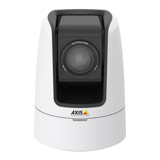
Axis V5915 Installation Manual
Axis v59 series
Hide thumbs
Also See for AXIS V5915:
- User manual (64 pages) ,
- Installation manual (147 pages) ,
- Installation manual (109 pages)
Subscribe to Our Youtube Channel
Summary of Contents for Axis AXIS V5915
-
Page 1: Installation Guide
AXIS V59 Series AXIS V5914 Network Camera AXIS V5915 Network Camera Installation Guide... - Page 2 Every care has been taken in the preparation of this • document. Please inform your local Axis office of any Electromagnetic Compatibility (EMC) Directive 2004/108/EC. See Electromagnetic Compatibility (EMC) inaccuracies or omissions. Axis Communications AB cannot on page 2 .
- Page 3 FAQ database. 使⽤して接続してください。また適切に接地し Search by product, category, or phrase てください。 • report problems to Axis support staff by logging in to your private support area Korea • chat with Axis support staff 이 기기는 업무용(A급) 전자파적합기기로서 판매...
-
Page 5: Hazard Levels
AXIS V59 Series Safety Information Read through this Installation Guide carefully before installing the product. Keep the Installation Guide for future reference. Hazard Levels DANGER Indicates a hazardous situation which, if not avoided, will result in death or serious injury. -
Page 6: Safety Instructions
Axis or a third party. • Use only spare parts provided by or recommended by Axis. • Do not attempt to repair the product yourself. Contact Axis support or your Axis reseller for service matters. • Do not point the camera lens toward the sun or other high-intensity radiation sources because this could cause damage to the camera. - Page 7 WARNING • Risk of explosion if the battery is incorrectly replaced. • Replace only with an identical battery or a battery which is recommended by Axis. • Dispose of used batteries according to local regulations or the battery manufacturer's instructions.
-
Page 9: Installation Steps
Installation Guide This Installation Guide provides instructions for installing AXIS V59 Series Network Camera on your network. For other aspects of using the product, see the User Manual available at www.axis.com Installation Steps 1. Make sure the package contents, tools and other materials necessary for the installation are in order. -
Page 10: Hardware Overview
AXIS V59 Series Hardware Overview Power connector 3.5 mm, unbalanced audio in 3.5 mm, unbalanced audio out Network connector Microphone power LED (XLR) XLR, balanced audio in (left) XLR, balanced audio in (right) BNC connector (SDI) HDMI connector 10 SD card slot (SDHC) -
Page 11: Led Indicators
AXIS V59 Series LED Indicators Status LED Indication Unlit Connection and normal operation. Green Shows steady green for 10 seconds for normal operation after startup completed. Amber Steady during startup. Flashes during firmware upgrade. Amber/Red Flashes amber/red if network connection is unavailable or lost. - Page 12 (LPS) with either a rated output power limited to ≤100 W or a rated output current limited to ≤5 A. Audio Connector The Axis product has the following audio connectors: • Audio in – 3.5 mm input for a stereo microphone, or a line-in stereo signal.
-
Page 13: Specifications
• Resetting the product to factory default settings. See page 19. • Connecting to an AXIS Video Hosting System service or AXIS Internet Dynamic DNS Service. For more information about these services, see the User Manual. Specifications This section contains the following specifications: •... -
Page 14: Power Consumption
AXIS V59 Series Product Classification Temperature Humidity AXIS V5914 IEC60721-4-3 0°C to 40°C(32°F to 10-85%RH (non-condensing) Class 3K3, 3M3, 104°F) AXIS V5915 C60529IP52 Power Consumption NO TICE TICE TICE Use a limited power source (LPS) with either a rated output power limited to ≤100W or a rated output current limited to ≤5A. - Page 15 AXIS V59 Series Power Connector 2-pin terminal block for DC power input. Use a Safety Extra Low Voltage (SELV) compliant limited power source (LPS) with either a rated output power limited to ≤100 W or a rated output current limited to ≤5 A.
-
Page 16: Install The Hardware
AXIS V59 Series SD Card Slot Supports SD cards with up to 64 GB of storage. For best recording performance, use an SDHC or SDXC card with speed class 10. Install the Hardware There are three ways to install the camera:... -
Page 17: Drop Ceiling Mount
AXIS V59 Series Mounting bracket Tripod screw Outer mounting hole Camera 5. Route and connect all cables to the camera. NO TICE TICE TICE Be careful not to stretch or bend the cables too much. This could cause damage to the cables. -
Page 18: Connect The Camera To A Hdmi Display
AXIS V59 Series 3. Drill a 7 mm (9/32 in) hole in the ceiling tile. 4. Remove the tripod screw from the mounting bracket. 5. Attach the short end of the threaded rod to the camera and tighten. 6. Assemble the camera, ceiling tile and the mounting bracket and tighten the nut. -
Page 19: Access The Product
AXIS V59 Series If the display supports the maximum resolution of the camera, just connect the display without adjusting any settings. If the display’s maximum resolution does not match that of the camera, the capture mode in the camera has to be changed to match the resolution of the display. -
Page 20: Further Information
For the latest version of this document, see www.axis.com The User Manual is available at www.axis.com Visit www.axis.com/techsup to check if there is updated firmware available for your network product. To see the currently installed firmware version, go to Setup > About. - Page 22 Installation Guide Ver. M3.2 AXIS V59 Series Date: November 2015 © Axis Communications AB, 2015 Part No. 1539537...


Need help?
Do you have a question about the AXIS V5915 and is the answer not in the manual?
Questions and answers