Sharp UP-3300 Service Manual
Hide thumbs
Also See for UP-3300:
- Instruction manual (249 pages) ,
- Service manual (108 pages) ,
- Programming manual (40 pages)
Table of Contents
Advertisement
Quick Links
CHAPTER 1. SPECIFICATIONS. . . . . . . . . . . . . . . . . . . . . . . . . . . . . . . . . . . . . . . 1-1
CHAPTER 2. OPTIONS. . . . . . . . . . . . . . . . . . . . . . . . . . . . . . . . . . . . . . . . . . . . . . 2-1
CHAPTER 3. SERVICE PRECAUTION . . . . . . . . . . . . . . . . . . . . . . . . . . . . . . . . . 3-1
CHAPTER 4. PROGRAM RESET AND SRV MODE . . . . . . . . . . . . . . . . . . . . . . . 3-8
CHAPTER 5. MASTER RESET (ALL MEMORY CLEAR) . . . . . . . . . . . . . . . . . . . 5-1
CHAPTER 6. DIAGNOSTICS SPECIFICATIONS. . . . . . . . . . . . . . . . . . . . . . . . . . 6-1
CHAPTER 7. CIRCUIT DESCRIPTION . . . . . . . . . . . . . . . . . . . . . . . . . . . . . . . . . 7-1
CHAPTER 8. CIRCUIT DIAGRAM . . . . . . . . . . . . . . . . . . . . . . . . . . . . . . . . . . . . . 8-1
CHAPTER 9. PWB LAYOUT . . . . . . . . . . . . . . . . . . . . . . . . . . . . . . . . . . . . . . . . . . 9-1
PARTS GUIDE
Parts marked with "
" is important for maintaining the safety of the set. Be sure to replace these parts with specified
ones for maintaining the safety and performance of the set.
SERVICE MANUAL
CONTENTS
SHARP CORPORATION
CODE: 00ZUP3300USME
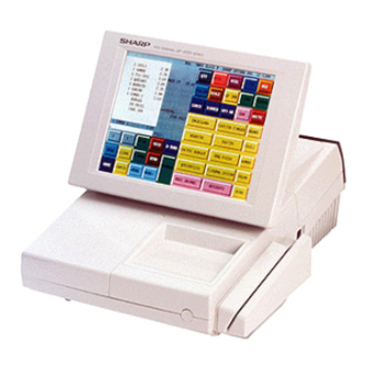
POS TERMINAL
UP-3300
MODEL
(For "U" & "A" version)
This document has been published to be used
for after sales service only.
The contents are subject to change without notice.
Advertisement
Chapters
Table of Contents

Related Manuals for Sharp UP-3300


Summary of Contents for Sharp UP-3300
- Page 1 SERVICE MANUAL CODE: 00ZUP3300USME POS TERMINAL UP-3300 MODEL (For "U" & "A" version) CONTENTS CHAPTER 1. SPECIFICATIONS........1-1 CHAPTER 2.
- Page 2 BATTERY DISPOSAL Contains Nickel Metal Hydride Battery. Must be Disposed of Properly. Contact Local Environmental Officials for Disposal Instructions.
- Page 3 10.4" Full screen 640 (W) × 480 (H) mm Full dot Dot format 0.09 × RGB(W) × 0.31 mm Dot size Dot space 0.02 mm ∗ Note that the application software for the UP-3300 uses 16 colors. 1 – 1...
- Page 4 Screen example (REG mode) Status indication Mode caption Time Window Touch-panel keyboard Numeric entry: An entered figure appears at the cursor position. NOTE: The size of a display area depends on the layout of a touch-panel keyboard (ex. key size) or the function mode (ex. drive-through function).
- Page 5 • Keyboard layout (default) Sub3 keyboard • This keyboard appears when you touch the MORE→ key on the Home keyboard Sub2 keyboard. This keyboard appears when touch the HOME key. DISC. MISC G.CHK MENU01 MENU02 MENU03 MENU04 MENU05 000001 000006 000011 000002 000007...
- Page 6 • • Function menu 3 (MISC) keyboard Payment menu (PAYMENT MENU) keyboard This keyboard appears when you touch the MISC key on the This keyboard appears when you touch the PAYMENT MENU Home, Main2, or Main3 keyboard. key on the Home, Main2, or Main3 keyboard. TAX1SF RLU/SB WASTE...
- Page 7 Function keys list (default keyboard and labels) Caption (default) Function Caption (default) Function HOME Used to return to HOME keyboard. %1 thru %9 Used to enter the percent calculation (percent 1 thru 9). CANCEL Used to cancel your current operation or menu or return to previous menu.
- Page 8 3) Screen save mode Caption (default) Function WAIT Used to shift the corresponding guest To save electrical power or the display’s life, your POS terminal is check to the wait mode (for drive-thru). provided with the screen save function. This function can turn the LCD backlight off when the POS terminal is left idle for an extended RECALL Used to re-call the corresponding guest...
- Page 9 CHAPTER 2. OPTIONS 1. System configuration INLINE Communication Satellite Remote printer <Option> <Local purchase> ER=04RP/03RP <Local purchase > (SRN) IR Communication RS-232 Communication Master machine (RS-232) (IR) RS-232 board <Option> ER-A7RS <Local purchase > R/J printer <Local purchase> <Option> ER-01PU Expansion Built in printer memory board...
- Page 10 Toledo, NCI Coin Dispenser Telequip Coporation Color Kitchen Monitor Progressive sys. This equipment will be purchased locally and it will be connected to UP-3300 via SRN and RS232 I/F. 4. Service options : None 5. Service tools NAME PARTS CODE PRICE...
- Page 11 5-2. MCR test card: UKOG-6718RCZZ Test pins : Used to check the bus signals. • Used when executing the diagnostics of the UP-E12MR2. • External view Bus connector : Used to check the bus signals. Connected to the UP-3300 Mother PWB. 2 – 3...
- Page 12 UP-3300 ........
- Page 13 4) Entering correction mode If the power supply is turned off during correction, the following messages are displayed and all the steps are started over again. The command "Entering correction mode" is issued to the touch panel controller. Calibration failed. At this step, the coordinate data of the four corners in the input Touch the panel to try again area are passed to the controller.
- Page 14 3300 series. The "UTL33.EXE" is a program which runs on the PC the application software written in it, and there is no need for DOS prompt screen, it is connected to the UP-3300 through IR. It has writing the application software when replacing the main PWB unit.
- Page 15 Turn ON the power. Starting of "IPL Mode". UP-3300 shows "IPL from IR" IPL from IR Connect P.C. and UP-3300 via IR. (Fig 1) Execute "UTL33.EXE" on P.C. Operation: >UTL33 3300_1.ROM 3300_2.ROM ("3300_1.ROM" and "3300_2.ROM" are file name of S-type ROM object.)
- Page 16 Procedure on UP-3300 side Install "UTL33.EXE" on the P.C. Enter the SRV mode. Then turn OFF the power or UP-3300. While pressing the On-Line key, tum ON the power of UP-3300. Keep pressing the On-Line key, and then press the Feed key also.
- Page 17 2: UP-T80BP LOGO STAMP "UTL33.EXE" is a utility program on P.C. - a program that sends the application program data of UP-3300, the image data of the Logo 3: UP-T80BP IPL stamp of UP-T80BP or the application program data of UP-T80BP in Normally, UTL33.EXE takes the suitable function automatically.
- Page 18 5. Conditions for soldering circuit parts To solder the following parts manually, follow the conditions described below. PARTS NAME PARTS CODE LOCATION CONDITIONS FOR SOLDERING RCRMZ7002RCZZ Ceramic oscillator MAIN PWB: X1 (8M) 270°/3sec. RCRMZ7004RCZZ MAIN PWB: X2 (7.37M) 270°/3sec. • How to Connect or Disconnect FFC 6.
-
Page 19: Chapter 4. Program Reset And Srv Mode
LOCATION QCNCW7217RC3J TOUCH CONNECTOR PWB: CN1 In the UP-3300, the following reset switch (location No: S1) is used to switch to the service (SRV) mode and to reset. • How to Insert FFC (1) Open the slider to unlock position PROGRAM RESET Open the slider upwards up to an angle of 60 degrees. - Page 20 8) MASTER RESET-1 is started. CHAPTER 5. MASTER RESET DISPLAY: (All Memory Clear) There are three possible methods to perform a master reset. MASTER RESET 1. MRS-1 (Master resetting 1): Clear the 9) After completion of the master reset, the buzzer sounds three entire memory and resumes initial times and the following SRV mode display is shown.
- Page 21 6) The master reset menu window is displayed as shown below. 10) After completion of the master reset, the buzzer sounds three times and the following SRV mode display is shown. DISPLAY: DISPLAY: [SRV mode screen] Please select MASTER RESET MASTER RESET 1 MASTER RESET 2 Touch the [MASTER RESET 2] key.
- Page 22 6) The master reset menu window is displayed as shown below. 9) Set the fixed keys in the table below (Start from the [HOME] key, The key are displayed sequentially) DISPLAY: DISPLAY: Please select ENTER HOME MASTER RESET MASTER RESET 1 MASTER RESET 2 KEY NAME HOME...
-
Page 23: Table Of Contents
UP-P02MB2. 1) Rear Display Check ............7 1) Master reset procedure 3-9. SHARP Retail Network Diagnostics........7 Turn off the power. 1) SRN Self Check.............7 Set the CKDC reset switch to RESET position. 2) SRN Flag Send Check...........8 3) SRN Data Send Check ..........8... -
Page 24: Ram Diagnostics
Check point address = 700000H, 700001H 700002H, 700004H UP-3300 Diagnostics V1.0A 700008H, 700010H Product & Test Diag IrDA Diag 700020H, 700040H 700080H, 700100H RAM Diag Drawer Diag 700200H, 700400H ROM & SSP Diag Rear Display Diag 700800H, 701000H 702000H, 704000H Clock &... -
Page 25: Rom & Ssp Diagnostics
The format of data (ASCII) to be stored is as Service ROM Check follows: SSP Check D1FFE0H ∼ D1FFEFH: Model name code (example: UP-3300. Display is made up to 00H of data.) D1FFF0H ∼ D1FFF9H: 27801R****(****=PROGRAM VERSION) D1FFFAH ∼ D1FFFBH: BLOCK NO. ("20" ∼ "2F") D1FFFCH: TERMINATOR ("=") -
Page 26: Timer & Clerk Switch Diagnostics
Check the time updated and indicated. When setting channels of RS232, do not set two or more ports to one channel. In the UP-3300, max. two units of ER-A7RS can be Timer Diagnostics installed. In each PWB, do not set two or more ports to the same DATE &... -
Page 27: Ch1 Check
• ER-A7RS CON3 Data transfer check The loop back data (256 bytes) of 00H ∼ 0FFH are used for S1-1 S1-2 S1-3 CHANNEL data transfer check. The baud rate is set to 38400BPS. Invalid • Timer check (RS232 on board timer) CHANNEL 1: Do not set this (Reserved for Before performing the check, set the timer to TCVDT start and... -
Page 28: Ch6 Check
The check procedure, the display, and the terminating procedure are the same as CH1 Check. 3-7. Liquid Crystal Display Diagnostics The UP-3300 LCD display is checked. The test program displays the patterns in the following sequence. Every time when the Touch panel is pressed, the next pattern is vii. -
Page 29: Rear Display Diagnostics
The number of data received in DMA is abnormal. b3 The number of data transmitted in DMA is abnormal. 3-9. SHARP Retail Network Diagnostics b2 An overrun error is generated. The SRN test is performed. b1 An underrun error is generated. -
Page 30: Srn Flag Send Check
The error status from the controller to the host is as shown in 4) Data Transmission Check the table below. Data transmission is checked in an actually composed system. The system is composed of one master machine and max. 15 satellite b7 Not used. -
Page 31: Irda & Ask Diagnostics
UP-3300 quence No. and 256byte AAH data. In case of an error, the • UP-3300 as checker master machine displays an error code and terminates the The following menu is displayed. Press the touch key for the opera- check. If two or more satellite machines are used, the above tion you want to execute to execute individual Diag programs. -
Page 32: Irda & Ask Check
1) IrDA & ASK Check Display IR communication is checked between the UP-3300 sending unit and Data Transmission Check (Send MODE) the receiving unit. COUNTER : **** (The RING COUNTER (0~9999) is displayed Check content • Data transmission is made from the machine to be checked in ASK format. -
Page 33: Drawer 1 Check
1) Drawer 1 Check Indication Check content The indication is the same as that for RS232 DIAGNOSTICS. The solenoid of drawer 1 is turned on, and the drawer open sensor value is sensed at every 100ms, and the state is displayed. Press the PANEL to end the program. -
Page 34: Chapter 7. Circuit Description
CHAPTER 7. CIRCUIT DESCRIPTION 1. Hardware block diagram Drawer x 2 DRIVER +24V H8/510 DRIVER +24V FLASH MPCA8 RS232 x 2 DRIVER/ PSEUDO RECEIVER SRAM OPC2 EXT.SLOT (80pin x 2) RAMCN (72pin) PRINTER VRAM TOUCH PANEL CONTROLLER (DRAM 512K) VFD CONTROLLER CKDC9 CONTROLLER MN89303A... - Page 35 2. Description of main LSI’s 2-1. CPU (HD6415108FX) 1) Pin description AVSS 7 – 2...
- Page 36 2) Block diagram P27/A23 P26/A22 Data bus Port 1 P25/A21 P24/A20 P23/A19 P22/A18 P21/A17 P20/A16 EXTAL XTAL Clock Watch oscillator dog timer H8/500 CPU STBY Interruption controller 16bit free running Refresh controller timer x 2ch RFSH BREQ BACK Wait state 8bit timer controller WAIT...
- Page 37 Data bus /STOP System reset output signal Data bus /IPLON0 From IPL SW of ER-A7RS Data bus /IPLON1 From IPL SW of UP-3300 Data bus Data bus NORDY Flash Memory ready ("H" active) Data bus FVPON Flash Memory write protect ("L"...
- Page 38 2-2. G.A.(MPCA8) 1) Pin configuration EXINT0Z EXINT1Z PCUTZ EXINT2Z FCUTZ EXINT3Z WROZ STAMPZ RDOZ VIOZ RA15 VMEMZ RA16 SWAPZ RESZ RA17 FROS1Z RA18 FROMLZ EXWAITZ POFF WAITZ INT1Z MCR2Z HTS1 IPLON SCK1 DAX2 STH1 DAX1 MCRINT RCRXZ VWAITZ IRRXZ MCRINTZ UATXZ VRESC UARXZ...
- Page 39 2) Block diagram M P C A 8 A23-A0 IPLONZ VMEMZ DROS1Z SSP COMPARISON RASPN1 REGISTER SSPRQZ DECODE RASPN1E RASPN12Z RASPN2 RASPN2E IRTX IRRXZ RCRXZ D0-D7 BUFFER UASCK CONTROL UARXZ UATXZ DAX1 RDOZ DAX2 READ WROZ WRITE PHAI CONTROL TXDI RESETZ SCKI RESZ...
- Page 40 3) Pin description Name Description Name Description RXDI SERIAL OUT FOR CPU TXDI SERIAL IN FROM CPU PCUTZ SCKI SERIAL CLOCK FROM CPU FCUTZ IRQ0Z INTERRUPT SIGNAL FOR CPU ADDRESS BUS STAMPZ ADDRESS BUS VIOZ ADDRESS BUS VMEMZ VRAM DEOCDE ADDRESS BUS SWAPZ ADDRESS BUS...
- Page 41 Name Description Name Description 100 VDD – 150 HTS2 SERIAL OUT (OPTION CKDC INTERFACE) 101 GND – 151 SCK2 SERIAL CLOCK (OPTION CKDC 102 IRRXZ IR IN FROM IR UNIT INTERFACE) 103 RCRXZ 152 STH2 SERIAL IN (OPTION CKDC 104 DAX1 OSCI IR CLOCK (7.37MHz) INTERFACE) 105 DAX2...
- Page 42 2-3. OPC2 1) Pin configuration SL00 TRNDTB SL01 /CSB SL02 SL10 SYCBKA SL11 TRNEMPA SL12 RCVRDYA SL20 TRNRDYA SL21 /DSRA SL22 /CTSA SL30 RCVDTA SL31 /RTSA SL32 /DTRA /CD0 TRNDTA BRK0 /CSA TRNEMP0 UTST RCVRDY0 DBTST TRNRDY0 RCVCLK /CTS0 TRNCLK RCVDT0 /CI0 /RTS0...
- Page 43 OPC1 DATA BUS OPC1~USART BAUD RATE GENERATOR BAUD RATE GENERATOR USART USART USART USART USART Common input 3) Pin description Name UP-3300 Description Name UP-3300 Description SL00 RS-232/UNIT0 24 /CS0 /CS1 RS-232 chip select channel select signal SL01 25 /CD1...
- Page 44 Name UP-3300 Description Name UP-3300 Description 40 RCVDT2 RCVDT3 RS-232 reception to 90 DB1 DATA BUS (USART) send signal 91 DB2 DATA BUS (USART) 41 /CI2 92 DB3 DATA BUS (USART) 42 /CS2 /CS3 RS-232 chip select 93 GND signal...
- Page 45 • The Z80 microprocessors and associated family of peripherals can Name UP-3300 Description be linked by a vectored interrupt system. This system can be daisy-chained to allow implementation of a priority interrupt 131 /CSC /CS3 USART_C chip select scheme. 132 TRNDTC...
- Page 46 3) General description Signal Symbol In/Out Function name The CPUs are fourth-generation enhanced microprocessors with ex- ceptional computational power. They offer higher system throughput S RDS Rread signal and more efficient memory utilization than comparable second- and S WRS Write signal third-generation microprocessors.
- Page 47 During operation, the individual counter channel counts down from the preset time constant value. In counter mode operation the counter CLK/TRG0 decrements on each of the CLK/TRG input pulses until zero count is ZC/TO0 reached. Each decrement is synchronized by the system clock. For counts greater than 256, more than one counter can be cascaded.
- Page 48 3) Pin configuration Signal Symbol In/Out Function name Signal Symbol In/Out Function — name S A1 Channelselect signal READY READY Ready signal 36 CLK/TRG3 S TM1 External clock / timer signal HLDAK HLDAK Hold acknowledge signal 37 CLK/TRG2 S TM0 External clock / timer signal ASTB S ASTB...
- Page 49 The MB62H149 is a semi-custom LSI chip for the peripheral circuits (b) CPU and DMAC wait signal control unit in the SRN (SHARP Retail Network), its main function is to communi- Clocks into the CPU (Z-80), SUB CPU and its peripheral LSI, cate data with the host CPU and control the peripheral circuits and DMAC and CTC are operated respectively on 4 MHz.
- Page 50 3) Terminal Name and Description (MB62H149) Terminal Host/ Description name IO/WR I/O write 23.9 ± 0. 6 IO/RD I/O read Address enable from DMAC Address strobe from DMAC Terminal count DAK23 DMA acknowledge 2+3 DRQRS DMA request read to sub DRQWS DMA request write to sub Host...
- Page 51 2-8. VGA controller (MN89303A) 1) Pin Configuration /SBEH /IOWR /IORD /SMEMW /SMEMR SA19 SA18 LOGICON SA17 LCDON SA16 BACKON SA15 SA14 SA13 SA12 SA11 SA10 /BIOSEN /REFRESH 2) Block diagram Gray scale RAM table engine Hardware UD[7:0] cursor LD[7:0] BACKON LCD panel LCDON controller...
- Page 52 3) Pin configuration Signal Signal Symbol Function Symbol Function name name 25.175MHz DCLK Out Data shift clock DISP DISP Out Display enable /SBEH /SBEH System byte high enable Out Line pulse /IOWR /IOWR I/O write OUt Frame pulse /IORD /IORD I/O read Out Upper data /SMEMW...
- Page 53 — 1) General description VCKDC — The CKDC7 is a 4-bit microcomputer developed for the UP-3300 and Clock signal provides functions to control the real-time clock, keys, and displays. Key data from host The basic functions of the CKDC7 are shown below.
- Page 54 2-10. ISP2032 Name Function This IC has been developed specially for UP-3300 to achieve VGA RASPN2E EXTENDED PSRAM2 DECODE CHIP and PSRAM interfaces. (FROM MPCA) Pin descriotion 800000H ∼ 9FFFFFH RASPN2 EXTENDED PSRAM2 DECODE Name Function (FROM MPCA) 800000H ∼ 9FFFFFH...
- Page 55 Fig. 4 3-4. ROM space 3-5. VRAM & RAM space Fig.5 shows the ROM space. The UP-3300 uses 2MB of NOR-type The VRAM is the display memory of the LCD. flash memory instead of conventional ROM, so that the ROS1 from...
-
Page 56: Customer Display
3-6. Extended I/O area The addresses from F00000h to FFFFFFh are called an extended I/O area. The UP-3300 uses the following addresses as the break ad- dress register (BAR) for SSP. • FFFF00h ∼ FFFFFFh 4. LCD display The main display is a 640 × 480 dot liquid crystal display. - Page 57 The figure below shows a typical pseudo SRAM interface in the up- 8. SSP control 3300. ISP2032 The UP-3300 uses flash memory in the place of EPROM, so it is Odd side PSRAM possible to rewrite the contents of the flash memory in changing the /OWR...
- Page 58 VGA controller. Extension RAM connector terminals Signal Signal Signal Name Name Name 11. CKDC9 — — The UP-3300 performs the following controls, using CKDC9. • Customer display — — • Clock — — • Buzzer —...
- Page 59 (system reset) and CKDCR signal (CKDC reset) are different ters. from each other. in the UP-3300, MRS, SRV resetting is selected and executed by the key which has bee depressed when the CKDC reset is released to start the system.
- Page 60 However, while the ER-A5RS uses the IRQ2 terminal of the CPU for worn magnet stripe. interruption of the RS232, the UP-3300 cannot use the IRQ1 terminal instead of it. (The IRQ2 terminal is used for IR as the SCK1 terminal.) 19.
-
Page 61: Chapter 8. Circuit Diagram
CHAPTER8. CIRCUIT DIAGRAM 1/16 1. Main PWB H8CPU IPLON0 R222 R219 R147 R132 R135 R137 R139 R144 R212 R249 R231 R237 R148 /RFSH R248 R247 R145 /LWR 10K X8 R140 /HWR R138 100pF IC30 R136 C233 C217 C237 C252 /RESET STBY C230 C250... - Page 62 2/16 DISPLAY MD[0..15] IC33 MD15 MD14 C257 MD13 47pF MD12 IC27 MD11 MD10 /VMEM /VHEM /VIO2 /VIO2 C168 /VHEM2 /SBHE /SBHE /VMEM2 0.1uF OS 33uF/10V /HWR /HWR /IORW /IOWR /LWR /LWR /IORD /IORD DHAI /COE0 IC27 VCC --- GND /ISPEN /SMEMW /SMEMW R149...
- Page 63 FLASH ROM 3/16 C182 0.1uF 10uF/16V IC29 VCC --- GND D[8..15] A[0..20] IC29 DQ10 DQ11 DQ12 DQ13 DQ14 DQ15 /FROS1 D[0..7] /HWR R184 /HWR FVPON /RES NORDY RY/BY /IPLON0 /IPLON0 BYTE C199 100pF LH28F016SUT...
- Page 64 PSRAM 4/16 VMEM /PSRFO IC43A VMEM /PSREF /RESET 74LVX08 IC34 20PIN - - - VCC IC21D ODD SIDE D[0..7] 10PIN - - - GND D[8..15] 74LVX00 IC37 IC34 VMEM IC19A VMEM VMEM 74LVX32 /M3SWP RASPN1 IC22B 74AHCT245NS IC24A /PCE1_O from MPCA /RESET 74LVX00 74LVX32...
- Page 65 MPCA8 5/16 IC23 14PIN - - - VCC 7PIN - - - GND IC23B IC20 RASP RCP2 RCP2 C126 C135 C139 PCUT LCDWT R105 74LS393 from MCR C131 C137 FCUT CLS2 CLS2 10K X2 RDD2 RDD2 STAMP TEST2 330pF X5 IC23A TEST1 C152...
- Page 66 OPC2 6/16 CLK_USART SL00 MCLK RES_USART SL01 SL02 RSLCT1 SL10 RSLCT0 /RDH SL11 /WRH SL12 SL20 SYCBKD SL21 TRNEMPD SL22 RCVRDYD SL30 TRNRDYD 0.1uF SL31 DSRD 10uF/16V SL32 CTSD /DCD1 RCVDTD BRK1 BRK0 RTSD TRNEMP1 TRNEMP0 DTRD RCVRDY1 RCVRDY0 TRNDTD TRNRDY1 TRNRDY0 /CTS1...
- Page 67 RS232 7/16 330pF FB25 /CI1 /CI1 BLM31 IC4C 100pF 75189 330pF C221 10uF/16V /DCD1 /DCD1 0.1uF R115 BLM31 IC4D 100pF R102 R130 75189 10K X3 to PRINTER -12V CN20 +12V FB34 RCVDT3_1 BLM31 FB33 TXD3 FB35 BLM31 /DTR3 BLM31 FB17 FB36 TXD1 /DSR3_1...
- Page 68 SRN1 8/16 IC14 14PIN - - - VCC IC14 VCC---GND C106 7,10,11,13PIN - - - GND S_WAIT- 0.1uF S_RES- 100pF 10uF/16V 0.1uF 0.1uF S_D0 C136 IC14A 10uF/16V 0.1uF 74HC74 X 16 S_D1 C129 S_M1 S_A0 S_A0 S_D0 S_A1 S_A1 S_D1 C119 S_D2 S_MRQ-...
- Page 69 SRN2 9/16 IC42D KIA7806 74LV08 SRN_+12V SRN_+12V SRN_+12V 0.22uF/50V 0.1uF/50V 150 3W IC42C 2SJ187 2SC4699K SRN_RTS 1.6K 74LV08 1.6K CFI06B1H101 SFPB54 5045-02 1SS353 (SRN CN) 51 1/2W (NOT INSTALL) 1SS353 BFD3580R2F 1.2K 1SS353 2SC4699K 3.9KG STRB IC5B 3300pF SN75115 0.1uF 1.5KG 20K VOL.
- Page 70 MCR I/F 10/16 MCR CN CN17 4.7KX6 FB22 FB19 CLS1# CLS1 RDD1# FB16 RCP1# FB12 CLS2# RDD2# RCP2# RDD1 5045-0810 BLM31 X6 RCP1 CLS2 RDD2 RCP2...
- Page 71 CLERK I/F 11/16 U/A NOT USED IC48,IC49 - - - 14PIN VCC 7PIN GND IC48 CN13 FB39 BLM31 IC46A 74LS125 74HC138 IC49 FB40 GIL-G-12P-5ST2-E CN14 (WMF CN) /CFSR BLM31 IC46B 74LS125 74HC138 FB41 53014-0810 0.1uF 0.1uF 1SS353 X7 (CLERK CN) BLM31 IC46C 74LS125...
- Page 72 CONNECTOR 12/16 CKDC CN VCKDC CHIP 0.1uF 47uF/25V VCKDC MOTHER CN CN4A A[0..19] /SCK IC40 VCC---GND /KRQ /SHEN /RDO BUZZ IC40B /RESETS IC40A /RESET /WRO /RESET 74HC00 A[0..23] 74HC00 /STOP /POFF VCKDC 1000PF 1000PF /PCE22_E -32V 1000PF /PCE21_E /PSREF /PCE22_O /CFSR /PCE21_O (RUN)
- Page 73 DRAWER 13/16 +24V VRES +24V 0.1uF /DRAW0 /DR0 /DRAW1 /DR1 +24V BFW7550R2 DRSNS TD62308F CN16 BFW7550R2 C254 5045-03A 0.1uF DRAWER CN1 CN15 FB13 BFW7550R2 C255 5045-03A 0.1uF DRAWER CN0 FB27 DRSNS DOPS BLM21 2.2K 1000pF...
- Page 74 VCC/INV_+12V CIRCUIT 14/16 [ VCC POWER CIRCUIT ] C124A 0.1uF +24V KTD1415 IC18A MC34063 R100A R104A R86A 3.6K F C20A 5.6K C21A 220uF/10V OS 33uF/10V OS R89A ZD4A VRESC C22A 180uH RD5.6PB3 1000uF/16V C121A 2SA1270 220pF D20A R108A SFPB54 1.2K F VRES [ INV_+12V POWER CIRCUIT ] INV_+12V...
- Page 75 +24V POWER CIRCUIT 16/16 IC36A L4960H +24V +24V 220uH R235A R262A C239A T2.5AL/250V CN7A 2200pF BD1A ZD5A UL/CSA 1.5A/125V CP301 RD30PB C47A VINA R229A SFPL52 C40A C36A 100uF/50V C38A 2.2uF/ 2200uF/ VINB 0.01uF/100V R238A (103K) 4.7K C235A MLX 5274-02A 33000pF R226A 4.3K D14A...
- Page 76 2. CKDC PWB 112-LT-04GK 3 4 5 6 7 8 9 2K X7 -32V 100K X7 -32V 100K X4 S1/2 -32V 100K DG11 DG12 2K X4 -32V DG10 DG13 DG14 DG15 VCC2 60 VCKDC 100K 32.768KHz /RESETS 13/RESET /DCS 14/CS /DSCK 15 SCK 16 SDATA...
- Page 77 3. IR PWB R104 C103 0.1uF IC101 R103 C102 0.33uF C101 0.033uF S101 CN101 /IPLON1 ASK/IRDA IRTX 53015-0510 R101 QNCM7226BH0E C106 330pF RPM-851 R102 C104 C105 4.7uf/16v 10uF/10V OS...
- Page 78 4. LCD PWB VCON VCON LCDON1 DISP DISP DL[0..7] CN31 52437-3091 DU[0..7] DISP VCON...
- Page 79 5. INVERTER PWB CN502A +12V SHUTDOWN- VR2-1 VR2-2 53015-0510 C504A 22pF/3.15KV GNDP GNDL T501A F601A 841TN-1157 ICP0.5 CN501A R501A VLOW COLOR VHIGH 12K F BHR-03VS-1 VLOW MONO VHIGH C501A R602A 2.2uF/50V C103 C502A M60-04-30-134P R603A C601A IC501A 220K 1000pF 2.2K 22uF/16V MITSUMI NOT USED...
- Page 80 6. MOTHER PWB 47uF /25V CN12A CN11A CN10A /RDO /RDO /RDO /WRO /WRO /WRO +24V +24V +24V /RESET /RESET /RESET /OPTCS /OPTCS /OPTCS SYNC SYNC SYNC MCRRDY1 MCRRDY1 MCRRDY1 MCRRDY2 MCRRDY2 MCRRDY2 /MCR1 /MCR1 /MCR1 /MCR2 /MCR2 /MCR2 CLK_USART CLK_USART CLK_USART CN12B CN11B...
- Page 81 7. N/F PWB UNIT N/F PWB (U/A) 120V POWER TRANS CN1A SW1A RCILC6654BHZZ CN2A PSCN VINA 1/2W 0.1uF 0.1uF 390K 250v VINB 250V UL/CSA 1.5A/125V POWER SWITCH BLOCK T/M TRCN...
- Page 82 8. TOUCH PANEL PWB AVCC VCCD 1SS353 DTA124EKA *PSW0 AVCC VCCD 1SS353 1SS353 *PSW1 EROMCK DTA124EKA EROMSO EROMSI EROMCS 0.1uF 1SS353 PSW2 VCCD DTC124TKA S-29390AF AVCC AVSS (E ROM) 10KX3 *PSW 1SS353 T/PRES- *RST DTA124EKA *RXINT TPTXD TPRXD 1SS353 PSW4 DTC124TKA 330pFX2 1SS353X4...
-
Page 83: Chapter 9. Pwb Layout
CHAPTER9. PWB LAYOUT MAIN PWB [A side]... - Page 84 [Bside]...
- Page 85 2. CKDC PWB [A side] [B side] 9 – 3...
- Page 86 3. IR PWB 4. LCD PWB [A side] [B side] 5. INVERTER PWB [A side] [B side] 9 – 4...
- Page 87 6. MOTER PWB (Side-A) 7. N/F PWB 8. TOUCH PANEL PWB 9 – 5...
- Page 88 UP-3300U/A PARTS GUIDE UP-3300 MODEL (for U.S.A., Canada) CONTENTS Top cabinet etc. Bottom cabinet etc. Packing material & Accessories Main PWB unit Mother PWB unit Touch panel PWB unit N/F PWB unit Invertor PWB unit Rear display PWB unit IR PWB unit...
-
Page 89: Top Cabinet Etc
UP-3300U/A 1 Top cabinet etc. PRICE PART PARTS CODE DESCRIPTION RANK MARK RANK 1 G S T N - 2 0 0 5 B H Z Z Tilt stand 2 J K N B Z 2 4 1 1 B H Z Z Tilt knob 3 M S P R P 2 3 7 2 B H Z Z Tilt spring... - Page 90 UP-3300U/A 1 Top cabinet etc. PSPS0020 – 2 –...
-
Page 91: Bottom Cabinet Etc
UP-3300U/A 2 Bottom cabinet etc. PRICE PART PARTS CODE DESCRIPTION RANK MARK RANK 1 L X - B Z 6 7 8 2 B H Z Z Screw (3×8KS) 2 P S H E P 2 8 6 0 B H Z Z R-disp sheet 3 C P W B F 7 5 7 6 B H 0 1 Rear-Disp PWB unit... - Page 92 UP-3300U/A 2 Bottom cabinet etc. PSPS0021 – 4 –...
-
Page 93: Packing Material & Accessories
UP-3300U/A 3 Packing material & Accessories PRICE PART PARTS CODE DESCRIPTION RANK MARK RANK S P A K C 3 0 1 9 B H Z Z Packing case [U.S.A] S P A K C 3 0 2 0 B H Z Z Packing case [Cnada] 2 S P A K A 8 4 5 4 B H Z Z... -
Page 94: Main Pwb Unit
UP-3300U/A 4 Main PWB unit PRICE PART PARTS CODE DESCRIPTION RANK MARK RANK 1 Q S O C Z 1 0 1 2 A C 7 B Socket (MM20-72B2-1-T24) [CN9] R C I L Z 5 0 1 7 S C Z / Chip core (BLM31) [FB1,2,3,6,7,9,10,11,12] R C I L Z 5 0 1 7 S C Z /... - Page 95 UP-3300U/A 4 Main PWB unit PRICE PART PARTS CODE DESCRIPTION RANK MARK RANK 60 V C K Y T V 1 H F 1 0 4 Z Capacitor (50WV 0.10µF) [C238,244,245,246,,220,254,255] 61 V H D 1 S S 3 5 3 / / - 1 Diode (1SS353) [D4,5,6,7,12,13A,16A,17A,18,19A] 62 V H D S F P B 5 4 / / - 1...
- Page 96 UP-3300U/A 4 Main PWB unit PRICE PART PARTS CODE DESCRIPTION RANK MARK RANK Resistor (1/10W 9.1KΩ ±2%) 120 V R S - T S 2 A D 9 1 2 G [R84A,85A] 121 V S 2 S A 1 0 3 6 K Q R C Transistor (2SA1036KQRC) [Q9A] 122 V S 2 S C 2 4 1 2 K / - 1...
-
Page 97: Mother Pwb Unit
UP-3300U/A 5 Mother PWB unit PRICE PART PARTS CODE DESCRIPTION RANK MARK RANK 1 Q C N C M 7 2 0 3 R C 8 J Option connector (20-5061-080) [CN12] 2 Q C N C W 7 2 0 4 R C 8 J I/O connector (80PIN;ST 10-5061-080) [CN4,10,11] 3 V C E A P S 1 E C 4 7 6 M... -
Page 98: Rear Display Pwb Unit
UP-3300U/A 8 Invertor PWB unit PRICE PART PARTS CODE DESCRIPTION RANK MARK RANK 12 V C K Y T V 1 H B 1 0 2 K Capacitor (50WV 1000PF) [C103] 13 V H D S F P B 5 4 / / - 1 Diode (SFPB54) [D601A,602A] 14 V H V I C P S 0 . -
Page 99: Glcd Pwb Unit
UP-3300U/A 11 LCD PWB unit PRICE PART PARTS CODE DESCRIPTION RANK MARK RANK 1 Q C N C W 7 2 1 7 R C 3 J Connector (30pin)(04-6239-030-001-800) [CN2] 2 Q C N C W 1 2 3 0 A C 3 A Connector (31pin) [CN1] ( U n i t ) -
Page 100: Index
UP-3300U/A Index PRICE PART PARTS CODE RANK MARK RANK PSHEG2859BHZZ 1- 38 PRICE PART PARTS CODE RANK MARK RANK PSHEP2471BHZZ 1- 45 PSHEP2472BHZZ 1- 44 CKOG-6724BHZZ PSHEP2860BHZZ CPWBF7573BH01 2- 22 PSHEP2861BHZZ 2- 57 " 7-901 PSHEP2862BHZZ 2- 58 CPWBF7576BH01 PSPAG6729RCZZ 9- 17 "... - Page 101 UP-3300U/A PRICE PART PRICE PART PARTS CODE PARTS CODE RANK MARK RANK RANK MARK RANK RCILZ1003BHZZ VCEAPS1CC336M 4-129 RCILZ5017SCZ/ VCEAPS1CC475M " VCEAPS1EC476M 4- 44 4-191 " " RCORF1008ACZZ 4- 45 VCEAPS1HC104M RCORF2025HCZZ VCKYTV1CF105Z 1- 20 4- 53 RCORF2031SCZZ " 1- 50 8- 11 RCORF6691BHZZ 4-130...
- Page 102 UP-3300U/A PRICE PART PRICE PART PARTS CODE PARTS CODE RANK MARK RANK RANK MARK RANK VHISN74HC74D1 VRS-TS2AD912G 4- 32 4-120 VHISN74HCU04D 4- 33 VRS-TS2HD130J 4- 41 VHISN74LS393N VRSTS2AD1032F 4- 34 4- 80 VHISN75115NS1 VS2SA1036KQRC 4- 35 4-121 VHISN75189DR/ 4- 36 VS2SA1270-/-1 4-142 VHITD62308F-1...
- Page 103 UP-3300U/A COPYRIGHT C 1998 BY SHARP CORPORATION All rights reserved. Printed in Japan. No part of this publication may be reproduced, stored in a retrieval system, or transmitted, in any form or by any means, electronic, mechanical, photocopying, recording, or otherwise, without prior written permission of the publisher.
- Page 104 COPYRIGHT 1998 BY SHARP CORPORATION All rights reserved. Printed in Japan. No part of this publication may be reproduced, stored in a retrieval system, or transmitted, in any form or by any means, electronic, mechanical, photocopying, recording, or otherwise, without prior written permission of the publisher.
Need help?
Do you have a question about the UP-3300 and is the answer not in the manual?
Questions and answers