
Related Manuals for X-TREME scooter XB-504


Summary of Contents for X-TREME scooter XB-504
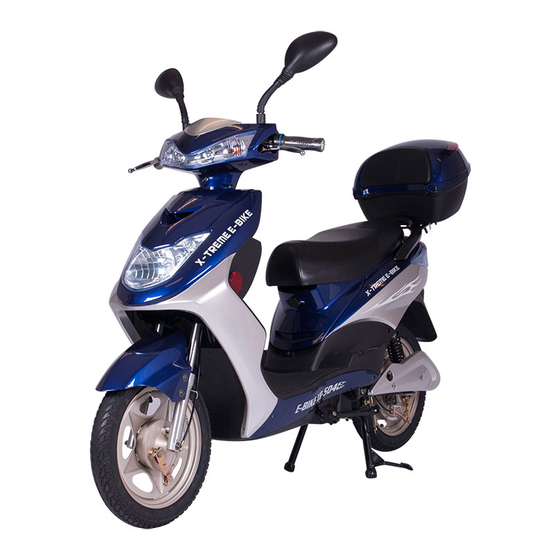
- Page 1 X-Treme Electric Moped XB-504 Electric Moped/Bicycle Owner’s Manual Read this manual completely before riding your electric bicycle...
-
Page 2: Table Of Contents
Table of Contents Table of Contents…………………………………………………………………………………. 2-3 Riding Safety……………………………………………………………………………………….. 4-6 Package Contents………………………………………………….……………………………… 7 Installation Instructions…………………………………………….……………………………… 7-10 Front Wheel & Brake………………………….…………………………………………….. 7 Handle Bar Installation………………………..…………………………………………….. 8 Face cover Installation..…….……………………………………………......8 Trunk/Pedals/Mirror Installation……….…………………………………………………… 9 Battery Connection & Initial Charging Instructions………………………………………. 9 Front Fender Installation……………………………………………………………………. 10 Tire Inflation………………………………………………………………………………….. - Page 3 How to Check Voltage………………………………………………………………………. 22 How To Test Motor Sensors……………………………………………………………….. 22-23 Troubleshooting…………………………………………………………………………………… 23-30 Scooter Won’t Run, Charger Light Stays Green…………………………………………. 23 Scooter Won’t Run, Charger Light Stays Red & Green………………………………… 24 Is It My Throttle or My Controller?................. 24 Throttle Voltage Test………………………………………………………………………… 25 Intermitted Power Loss……………………………………………………………………..
-
Page 4: Riding Safety
Never carry a passenger. The maximum carrying capacity is 300 lbs. Never ride barefoot or wearing sandals. Don’t jump with your XB-504. It puts great stress on everything from frame and forks to drive train. Riders who insist on jumping their XB-504 risk serious damage to their XB-504 as well as to themselves. - Page 5 Operating Reminders and Suggestions Review all instructions carefully before riding the XB-504. Follow all rules and regulations in your area for operating a motorized bicycle. Obey the same road laws as all other road vehicles, including yielding the right-of-way to pedestrians, and stopping at red lights and stop signs.
- Page 6 90 days. Do not store your XB-504 in direct sunlight for an extended time. Store your XB-504 in a dry place. Exposing your XB-504 to rain, snow, or other precipitation may result in damage. DO NOT RETURN TO STORE! Do not use this vehicle for the first time until you have inflated the tires to the correct PSI and completely charged the battery.
-
Page 7: Package Contents
Remove axle from front fork & shipping crate and set aside, do not discard. There are 8 installation steps that must be done prior to using your XB-504. Be sure to do them in order and do not skip a step. 1.) INSTALLATION OF FRONT WHEEL AND BRAKE. -
Page 8: 2.) Handlebar Installation
2.) HANDLEBAR INSTALLATION Locate and remove the handlebar bolt, washer & nut as shown above. Slide handlebars over post in the correct position, then insert the bolt & concave washer into the front (speedometer side) of the handlebars and secure with nut on the back (riders side). -
Page 9: Trunk/Pedals/Mirror Installation
6.) TRUNK, PEDALS & MIRROR INSTALLATION Attach trunk to back cargo rack using the 4 enclosed bolts/nuts & washers. Secure to rack with the washers & nuts on the underside. Attach left & right foot pedals according to correct side by lining up pedal with bearing on pedal shaft and snap into place. -
Page 10: Front Fender Installation
8.) FRONT FENDER INSTALLATION Locate and remove packing material from the front fender. Line up face cover to front fork of the scooter . Finally, secure to front of scooter using the 4 enclosed screws. 9.) TIRE INFLATION Finally, inflate both tires to the minimum recommended tire pressure depending on the number of riders that will be using the bike. -
Page 11: Product Specification
Product Specifications 1. Wire diagram 2. Specifications Battery Voltage 48Volt Dc,12Ah Motor Wattage 500W Wheel Size 16 inch Top Speed 20 MPH Charging Time 6-8h Distance of full charge 20 - 25 miles Battery charging cycles Around 350 times Max rider weight 300 Lbs Two rider Left and Right Indicators... -
Page 12: Operation
Operation Your new Electric Bicycle/scooter is a revolutionary new transport product using a sealed lead acid batteries and a super high efficiency electric hub motor designed to ASSIST in the propulsion of you and your bicycle. It is important to note the following riding guidelines to ensure you get the best possible experience from your electric bicycle. -
Page 13: Battery Charging & Safety
Battery Charging and & Battery Safety Charging Specification: 1.Input(AC) : 100-240V frequency:50Hz/60Hz 2.Output: 54.60 ± 0.2V 3.Charge current:1.8±0.2A Charging Ensure bike is turned off and key is removed. 1.First connect to the battery charger to the charging socket located below the front of the seat or under the front seat. - Page 14 4) Plug the end of the charger’s cord into the socket of the adaptor first. Next connect the adaptor to the XB-504 (the charger port in located below the front of the seat). Then plug the chargers’ AC cords into the wall outlet.
-
Page 15: Basic Maintenance & Schedule
Maintenance ----Basic 1. Your bike comes with a 30amp fuse, pre-installed at the factory and is located inside the battery box. 2. Clean Chain Regularly. 3. Ensure Tires are inflated to 35-45 PSI. 4. Adjust Brake tension via adjusting screws located at Brake lever or on Brake control lever. -
Page 16: Other Helpful Instructions
Other Helpful Instructions Pedals 1. Use a pedal wrench of 16mm spanner to tighten pedals. 2. Check and tighten pedal crank bolts with 14mm socket. Tires 1. Inflate tire using a pump to 35-45psi. Remember lower tire pressures will negatively impact performance by causing too much resistance, but over inflating may cause the tube to burst. -
Page 17: How To Guide
How To Assemble Rear Wheel 1. First, remove the two screws that hold the plastic plates on both sides of rear wheel. 2. Remove the screw from the end of Brake Cable, and then pull the cable out. 3. Remove the tightening screw. 4. -
Page 18: How To Remove Front Wheel
How To Remove Front Wheel 1. Remove the two nuts from both sides of the front wheel. 2. Remove the screw from the end of Brake Cable, and then pull the cable out. Then remove the axle and spacer as shown below. 3. -
Page 19: How To Replace Controller
to turn until the chain is totally off of the sprocket. Then remove the sprocket off of wheel sprocket. Remove wheel motor from scooter. How To Replace Controller Remove the Battery Pack from the scooter and set aside until new controller is installed. Open the seat and remove the four (4) seat barrel screws, two (2) near the Latch and two (2) in Front. -
Page 20: How To Center Handle Bars
Now the handle bar faring is ready to be removed, Start on the left side by where you removed the mirror. Gently pull the front and back of the handle bar fairing apart. It should snap apart fairly easily. Work your way across until the top is completely apart. Remove and replace. -
Page 21: How To Install Bearings
Next fine tune the adjustment by screwing the cable tension screw outward to pull on brake line until proper braking is achieved. Lock this position down by tightening the nuts. Avoid adjusting brakes on handlebars because there is a safety switch built into the handles to kill motor while using the brakes. -
Page 22: How To Check Voltage
How To Check Voltage Tools Needed: Multi-meter to read VDC First be sure the battery connector from the scooter is firmly attached to the battery case. Leave all connectors connected when measuring the voltage by sliding your meter probes into where the wires go on the backside of the connectors. -
Page 23: Troubleshooting
Blue. Now, there are two methods used to determine a bad connection or which of the three sensors have failed. Both require the motor to be fully assembled. The first is to simply run the motor while one sensor lead is disconnected, “refer to section-A below on how to do this”, then again for the second lead, and a third time for the last lead. -
Page 24: Scooter Won't Run, Charger Light Stays Red & Green
Troubleshooting: Scooter Won’t Run, Charger Light Stays Red & Green When you plug your charger into your scooter and the wall outlet the charger light stays green. This is telling me that somewhere between the batteries, fuse, and charger socket you have an open circuit. -
Page 25: Throttle Voltage Test
Troubleshooting: Throttle Voltage Test Follow throttle wires until you find its white connector. You will be testing the “Red”, “Green”, and “Black” wires. Set your meter to test DC volts. Block rear wheel off the ground so scooter will not take off. Turn the scooter on. Place the red meter test lead on the “Red” wire and the black meter lead on the “Black”... -
Page 26: No Power
Troubleshooting: No Power In this situation we will assume that the battery has been charged or allowed to stand for several hours (a battery will normally self-charge up to a point and make the scooter power up for a fair distance). -
Page 27: After Fully Charging, Powers Only For Short Distance Use
WARNING! Batteries contain acid that can explode, or the vapors ignite from an arc. Batteries produce current and voltage that can burn you when a shorted circuit occurs. Be absolutely sure you know what you are doing before trying any tests to eliminate a component from consideration of being defective!!! 3. -
Page 28: Charger
F) Wires behind fuse assembly have come off due to improper replacement of fuses or loose wire connections to the battery. This is always due to the customer rotating the whole fuse assembly (when changing fuses) and twisting the 2 wires that are in the back of the fuse holder. You must open up scooter and reattach these wires to back of fuse assembly or to battery and control box. - Page 29 Place the red meter lead on the red sensor wire. (7-20meg ohms) Place the red meter lead on the yellow sensor wire. (Infinite) 3. Place the red meter lead on the green sensor wire. (Infinite) 4. Place the red meter lead on the blue sensor wire. (Infinite) Place the red meter lead on the black sensor lead for the next three tests.
- Page 30 Common Causes To Complaints: Any customer complaints of jerky motor or motor not running have the customer check the sensor and motor connections at the controller and at the connectors at the rear of the moped. If this doesn’t help go to steps one or two below. If the customer complains that the moped is stuttering or jerking and moving slowly the most likely cause is that a motor sensor has failed and the motor will need to be replaced.
-
Page 31: Support
DO NOT RETURN TO STORE! IF YOU NEED HELP CALL OR GO ONLINE 1-253-777-0690 www.x-tremescooters.com/support/ For General Information or Parts Visit www.x-tremescooters.com Revised 05/20/13...
Need help?
Do you have a question about the XB-504 and is the answer not in the manual?
Questions and answers