Table of Contents
Advertisement
OPERATING MANUAL:
Instructions for use & maintenance of the
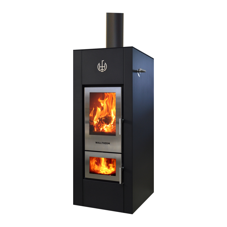
Walltherm®
Version / 12.1
The first natural down-draught wood gasification stove
for the living room.
Dear stove-owner,
You have made an excellent choice purchasing the Walltherm
stove/boiler for
®
your living room. Especially in connection with a heat storage tank, it offers you
all the advantages of a radiant heat stove for the living room and furthermore,
an economical heating system for your whole house. Please study this manual, it
explains how the stove works, how you should operate it and how it has to be
maintained.
For further information, please contact the manufacturer or any authorized
Walltherm dealer
progress & innovation
1/46
Advertisement
Table of Contents

Related Manuals for Wallnofer Walltherm


Summary of Contents for Wallnofer Walltherm
- Page 1 Version / 12.1 The first natural down-draught wood gasification stove for the living room. Dear stove-owner, You have made an excellent choice purchasing the Walltherm stove/boiler for ® your living room. Especially in connection with a heat storage tank, it offers you all the advantages of a radiant heat stove for the living room and furthermore, an economical heating system for your whole house.
- Page 2 BLT-Wieselburg (AUT), VKF (Switzerland) and TÜV Rheinland (GER). This operation manual is directed at the owner of the stove Mod. Walltherm, the tradesman who installs it, the operators, and the service personell. In any case of doubt or for further information concerning the manual, please contact the producer or any authorized Walltherm dealer.
- Page 3 CO (carbon monoxide) caused by incomplete combustion. This is a unique feature of the Walltherm stove for the living room. progress & innovation Vers. 12.1...
-
Page 4: Table Of Contents
Index 5.c.2. Limitation of space above the stove 1) Introduction 5.c.3. Combustion air 5.c.4. Smoke outlet pipe 1.a. Symbols 1.b. Intended use 1.c. Purpose and contents of the 6 Installation manual 6.a. Leveling the stove 1.d. Keeping the manual 6.b.1 Connecting Electricity 1.e. -
Page 5: A. Symbols
1.b. Use of the stove Walltherm is an innovative, technologically advanced stove for heating, burning fuels like firewood and wood briquettes providing a healthy and safe way of heating. This stove features the dual primary and secondary combustion system with positive effects both on efficiency and on emission of “cleaner smoke”. -
Page 6: F. General Information
Contents This manual contains all the information necessary for installation, use and maintenance of the Walltherm stove. By complying scrupulously with the contents of this manual you will ensure a high degree of safety and productivity of the stove. 1.d. Keeping the manual... -
Page 7: G. Main Accident Prevention
1.h. Legal guarantee Wallnöfer H.F. offers 5 years of guarantee for the body of the Walltherm, exclusiv spare parts like combustion jets, grid, glass, seals, cat, fireclay.. For all the valves an other components the user may only make use of the legal guarantee, as under the EEC... -
Page 8: J. User Characteristics
Please clean the external parts only with water and soap, do never use alcohol or similar agressiv cleaning liquids. b) To protect the upper side of the Walltherm® please close the exhaust fume flap (5) when the gas temperature reaches about 300 - 350°C. (look chapter: 7 Using the stove –... -
Page 9: L. Spare Parts
1.l. Spare parts Use genuine spare parts only! Do not wait until the components are worn from use before changing them. Changing a worn component before it breaks makes it easier to prevent accidents that could otherwise lead to serious harm to people or damage to things. ... - Page 10 2. Safety Precautions 2.a. Instructions for the installer comply with the indications given in this manual check that the flue and air intake are suitable for the type of installation opted for (12 pa draft) the electrical connections must not be done using temporary or non-insulated leads ...
- Page 11 3. Parts list of the stove 3.a. Spare parts/components Upper combustion chamber injektor block with secondary air feed Secondary air knob Grid Lower combustion chamber (gas combustion tunnel) Door with glass to lower combustion chamber Smoke channels Stove pipe flange with thermometer Horizontal smoke channels Opening with lid for access to smoke channels for cleaning Adjustable lid for smoke diversion...
- Page 12 Parts list of the stove: Front view top view 4 Handling und Transport Der Ofen wird mit allen vorgesehenen Teilen geliefert. Der Schwerpunkt des Heizofens liegt im hinteren Bereich. Dies ist auch beim Verstellen des Heizofens auf seinem Transport- Untergestell zu beachten. Gefahr: Sicherstellen, dass die Belastbarkeit des Hubstaplers über Fig.
- Page 13 View from Front view Backside right side dimensions are in mm Top view View from under the stove Chimney muff Air intake from under the stove progress & innovation Vers. 12.1...
- Page 14 I Forward flow II Backflow III Cold water IV Drain for thermal safety V Drain for overpressure valve A Security heat exchanger B Sensor thermal safety drain C Overpressure valve D Thermostat(sensor E Forward flow F Thermometer G Thermostat for air intake H Pressure gauge I Backflow J Fume sensor...
-
Page 15: Handling And Transport
4. Handling and Transport The stove is delivered complete with all the parts specified. Pay attention to the stove’s tendency to oscillate. Bear the above well in mind when moving the stove on the transport stand. Make sure the lifting capacity of the lift truck is more than the weight of the stove. - Page 16 5.c.1. Restriction of space around the stove The figure below (fig. 5.c.1.) shows the minimum distances to flammable materials and other items which have to be kept when installing the stove. adjoining wall back wall side wall floor protection Every item which is eventually flammable has to be protected from the heat.
- Page 17 If you would like to obtain the combustion air from outside, you can connect a canal. Follow the right of the installation country! On the Walltherm® we have two possibilities to connect the canal with the external combustion air: - On the bottom we have an aperture of Ø 180 mm on which we can connect the canal.
- Page 18 Right stove side Right stove side Top view Maintain distance to flammable objects! A external air cover B Air inlet from the backside 2 x 100mm Floor Floor Right stove side Right stove side View from under the stove Maintain distance to flammable objects! A external air cover B Air inlet from under the stove...
- Page 19 How does the cap for the external air connection work? The channel for the external air is connected from under the stove or from the backside. That air enters the lower part of the stove. From there the air exits, as you can see on the pictures below.
- Page 20 (rock wool) or to use double insulated steel pipes. If the chimney is not isolated, the Walltherm will most probably not work! There should be no horizontal parts in the exhaust pipe, because it corrupts the drought a lot! The chimney tube gets inserted into the muff of the Walltherm stove (see picture).
- Page 21 Danger: The connecting of the exhaust-pipe must not be connected with the following pipes: Chimney hoods which are already used for other heating systems (boilers, heaters, chimneys etc.); Ventilation systems (extractor hoods, ventilations etc.) even if they are running separately. Attention: Due to unfavourable conditions of the extractor hood (several bends, curves, unsuited chimney etc.) the smoke outlet may not work optimally.
- Page 22 6. Installation 6.a. Levelling of the wood-gasification stove Please level off the stove with the help of a spirit level. 6.b. Different connections 6.b.1. Electricity connection Please connect the thermostat, which was delivered together with the stove, with the heating pump and through a plug with the electric cable. The Thermostat needs to be set to at least 60°C! Inside the thermostat there are 4 connections.
- Page 23 WAL02 is also configurated with an ALARMFUNCTION this function will inform you when you have to close the exhaust fume flap WAL02 Digital regulation for the Walltherm® and a solar system: - regulation for the Walltherm with minimum temp. - with Alarmfunction* for the Walltherm...
- Page 24 Wiring of Walltherm and solar plant: A1 – Solar plant B1 – Water tank F1 – Walltherm stove R1 – Solar pump R2 – Stove pump T1 – Sensor for solar plant T2 – Sensor for tank temperature (inferior part) T3 –...
-
Page 25: C.2. Thermal Safety Drain
Earthing Danger: The system must be earthed and fitted with a circuit breaker as provided for by current laws (fig. circuit diagram). 6.c. Important indications 6.c.1. The doors The boiler must never be operated with open doors. Eventually out coming glowing materials can cause fire. -
Page 26: Using The Stove - Lighting
6.c.6. Cleaning The stove requires frequent and thorough clean and periodical inspection to guarantee it will work properly and to ensure constant heat efficiency. Use a vacuum cleaner to remove all the ash (when it is cold) that has collected in the stove. 7. -
Page 27: B. Lighting Phase
7.b. Lighting phase Before the lighting the turn flap/lever (5) must be opened for the exhaust switch over (lever pointing down) that the smoke is taken up gradually through the flue. Attention: Do not leave the exhaust fume flap opened constantly, the opened possition is only used to heat the stove up at the beginning. - Page 28 Spread on the two grills of the filling chamber (upper combustion chamber) about 5-6 sheets of crumpled newsprint (please begin at the front). Do not use cardboard. Then spread highly inflammable kindling (again begin at the front) over the complete width of the grill (quantity/amount: about 200 grams softwood or about 500 grams hardwood).
- Page 29 If the Walltherm® works correct you will see the following conditions: a) the gasification flame remains visible b) the temperature of the exhaust gases dropes down to 120 -150 °C c) the temperature on the reverse flow (pump group) grows to 60 – 75 °C.
- Page 30 Inside the stove: Exhaust fume flap (5) (9) cooking plate (4a) stove pipe (1) Upper combustion muff chamber Smoke chamber (2a) secondary air slide bar (10) (3) Lower combustion chamber (8) boiler Combustion jets The hot wood gases now draw/pass through the combustion jets into the lower gas ...
-
Page 31: C. Loading The Fuel
7.c. Loading the fuel Only open the door of the upper combustion chamber after the wood has burned off and changed into embers. Before putting some more wood on the fire please open the fume flap (5) (lever pointing down), wait a second, and then slowly open the door. - Page 32 How to set up the secondary air: By turning the round stainless steel knob directly between the upper and the lower combustion chamber, you can adjust the amount of air which enters the injector block of the stove. Attention: Mostly this doesn´t change the visual appearance of the flame! Adjusting the secondary air: Turn left = open the secondary air Turn right = close the secondary air...
- Page 33 C) The pump group We add one of the following pump groups to the stove: Forward flow Reverse flow Deaerator storage tank storage tank Thermal valve, set to at least 60°C Pump Temperature of the forward flow Temperature of the reverse flow (must be at least 60°C) Positioning of...
- Page 34 - Spinning the lever on the pump to 0 will change backlight color operating mode of the pump - For use with the walltherm the pump should be in standard mode where the LED is white, not blue! Lever White LED = manual control of the pump speed...
- Page 35 The firewood has to be dry. The natural drying process lasts 1 ½ - 2 ½ years. This process can occur outdoors (covered up) and should be continued in an appropriate shed. The Walltherm boiler is totally planned as wood boiler and is therefore for the following types of wood particularly suitable: Guideline for the storage chopped hardwood: max.
-
Page 36: Maintenance And Cleaning
8. Maintenance and cleaning 8.a. Safety precautions Prior to embarking on any maintenance work the following precautions must be taken: a) Make sure all parts of the stove are cold. b) Make sure the ashes are completely cold and not burning. c) Use the individual protective gear as established by the EEC directive 89/391. - Page 37 Periodical cleaning: There are two little ash boxes under the two stair grids. Please lightly lift the grids on the side of the jets and clean them. This is very easy when using a ash vacuum cleaner. This should be done every 2 weeks. To prevent the glass from the upper combustion chamber to get black you need to clean the air inlet which is right behind the upper door (stainless steel grill, see pictures below) Also clean the gap in between the door and the refractory stones in the lower combustion...
- Page 38 Also the grid in the lower combustion chamber and the injector block needs to be cleaned. To get the grid out, you need to lift the injector block! Grid Injector block Hole on the front needs to point to the door Monthly cleaning: The smoke channels should be cleaned every 6 –...
-
Page 39: B.2. Cleaning The Glass
Clean all channels with the long brushes! Important: Every brush must hit the bottom of the lower combustion chamber to make sure every channel is completely cleaned! Repeat until the channels are free of ash remnants. After cleaning the lower combustion chamber set in the grid on the right position. Please make shure the injector block is clean, otherwhise it could influence the drought! Make shure to insert the injector block with the hole on the front side pointing towards the front door. -
Page 40: Recognizing Errors And Taking
8.b.4. Controlling the sealing The sealing of the doors (upper and lower combustion chamber), the cooking plate (9), the opening with lid for access to smoke channels (4c) and the fume flap for exhaust switchover (5) must be checked yearly. If necessary, they have to be changed and at all events replaced every two years. -
Page 41: Saving Energy
10. Saving energy The temperatures of the rooms and how long the stove works represent great influences on the consumption of fuels. 1° C lower room temperature can effect an economizing/saving of fuels up to 6 %. Therefore please notice the following: Try to avoid room temperatures which are higher than 20°... -
Page 42: Concept Of Water Pipes
11. Concept of waterpipes progress & innovation Vers. 12.1... - Page 43 Indications for the connection to the pipe An emptying tap has to be installed in lowest area of the water circulation. The thermostat for pump’s beginning has to be set when it is in cold state. The stove’s heat exchanger must not be the highest part/point of the system! If ...
-
Page 44: Safety Functions
12 Safety functions Thermostat at the air inlet with thermostatically controlled flap (6a) A safety thermostat for control of combustion air intake 6b with connection bar and chain is connected with a thermostatically controlled flap for combustion air 6a. If the temperature of the boiler is higher than 80-95°... - Page 45 Thermal sfety drain Thermal safety drain in case of overheating (8b, 8c, 8e): As further safety precaution the oven has a thermal safety frain consisting of a safety valve 8b, a heat exchanger 8c, and a valve for thermal drain. In any case of over- temperature the valve 8e opens and makes the hot water flow towards the drain.
-
Page 46: Technical Features/Data
Thank you very much a South Tyrolean “Herzliches Vergelt’s Gott” Thank you very much for having chosen the Walltherm stove and please enjoy this innovative natural down-draught woodgasification stove. The Team Wallnöfer H.F. GmbH Energiesysteme 39026 Prad am Stj.
Need help?
Do you have a question about the Walltherm and is the answer not in the manual?
Questions and answers