Table of Contents
Advertisement
HF2013DX-A
HF POWER AMPLIFER
CAUTION
Before you turn the amplifier on, at least 2 hours should have expired since
it was brought in and unpacked in the room where it will be used. Pay
particular attention when you move it from a very cold into a very warm place
- condensation is likely and this could result in damage to the high voltage
circuits. In such a case, wait at least 4 hours. A similar effect can occur after
a rapid warming of the operating room (for instance after switching on a
powerful heater).
CAUTION
To avoid
Advertisement
Table of Contents

Summary of Contents for Ham radio HF2013DX-A
- Page 1 HF2013DX-A HF POWER AMPLIFER CAUTION Before you turn the amplifier on, at least 2 hours should have expired since it was brought in and unpacked in the room where it will be used. Pay particular attention when you move it from a very cold into a very warm place - condensation is likely and this could result in damage to the high voltage circuits.
- Page 2 Instruction Manual Version 1.09 HF2013DX-A HF AMPLIFER INSTRUCTION MANUAL Page 2 of 37...
-
Page 3: Important Safety Instructions
The amplifier must be installed so that free flow hot air from the tube is unrestricted. Do not install the amplifier in an area that could constrain airflow. HF2013DX-A HF AMPLIFER INSTRUCTION MANUAL Page 3 of 37... - Page 4 In such cases the user is to take proper actions to mitigate this disturbance, by using proper station earth, use of Ferrite beads, high quality antennas and high quality coax such as LMR400 or better. HF2013DX-A HF AMPLIFER INSTRUCTION MANUAL Page 4 of 37...
-
Page 5: Table Of Contents
GENERAL DESCRIPTION OF THE HF2013DX-A AMPLIFIER SPECIFICATION OF HF2013DX-A DESCRIPTION OF HF2013DX-A POWER AMPLIFIER PUTTING THE POWER AMPLIFIER INTO OPERATION COOLING OPERATION CONFIGURING AND OPERATING THE HF2013DX-A POWER AMPLIFIER TUNING TUNING INSTRUCTIONS INDICATION OF FAULT CONDITIONS HF2013DX-A HF AMPLIFER INSTRUCTION MANUAL Page 5 of 37... -
Page 6: General Description Of The Hf2013Dx-A Amplifier
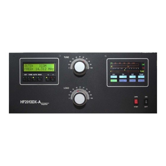
GENERAL DESCRIPTION OF THE HF2013DX-A AMPLIFIER The linear amplifierHF2013DX-A is designed for all short wave amateur bands from 1.8MHzto 29MHz (including WARC – bands) and all operating modes. It is equipped with anceramic tetrodeFU728F(4CX1500B). The HF2013DX-Ais automatically tuned to the operating frequency of your TRX when the correct control cable is connected. - Page 7 OPR/STBY Operate and Standby modes. OSD INDICATION LCD display 2x32 Characters Colour 5 inch LCD Information Panel DIMENSIONS: 485 x 200 x 455mm (width x height x depth) WEIGHT: 38 kg HF2013DX-A HF AMPLIFER INSTRUCTION MANUAL Page 7 of 37...
-
Page 8: Description Of Hf2013Dx-A Power Amplifier
DESCRIPTION of HF2013DX-A POWER AMPLIFIER In this amplifier a tetrodetubeFU728F (similar to a 4CX1500B)is used in a grounded-cathode circuit (input into control grid). This amplifier achieves excellent linearity by the voltage stabilization of the control grid bias and the screen voltage. The power input is given to the control grid, using a broadband input circuit with an input impedance of 50 Ohms. - Page 9 TOP VIEW OF OPENED HF2013DX-A SIDE VIEW OF OPENED HF2013DX-A HF2013DX-A HF AMPLIFER INSTRUCTION MANUAL Page 9 of 37...
- Page 10 POWER SUPPLY BOARD OF THE HF2013DX-A SWITCH ON BOARD OF THE HF2013DX-A HF2013DX-A HF AMPLIFER INSTRUCTION MANUAL Page 10 of 37...
- Page 11 AC POWER CONNECTORS AND COOLING FAN TOROIDAL TRANSFORMER 2.0 KVA HF2013DX-A HF AMPLIFER INSTRUCTION MANUAL Page 11 of 37...
-
Page 12: Putting The Power Amplifier Into Operation
2KW each. If connected to a single phase, ensure your mains supplyis able to deliver 4KW. Failure to do this will result in limited RF output and could cause issues with RFI. HF2013DX-A HF AMPLIFER INSTRUCTION MANUAL Page 12 of 37... - Page 13 CINCH-socket is used. On the side of your transceiver you have to use a socket suitable for your transceiver. The relays of the HF2013DX-A have to be switched earlier than HF is applied (cold switching). Modern transceivers have a time delay between PTT switching and power output. If you are...
- Page 14 1. ALC Out 2. NC 3. INHIBIT Control voltage 4. TX INHIBITfor Yaesu and Elecraft – this supersedesALC output 5. NC 6. KEY OUT 7. NC 8. KEY IN 9. – 15. GND HF2013DX-A HF AMPLIFER INSTRUCTION MANUAL Page 14 of 37...
-
Page 15: Cooling
Thesupplemental rear mounted fan is turned on depending on the temperature of the air exiting from the tube tower of the amplifier. It is activated when the exit temperature exceeds 70°C and is switched off at 60°C. HF2013DX-A HF AMPLIFER INSTRUCTION MANUAL Page 15 of 37... -
Page 16: Operation
OPERATION TUNE Anode capacitor for tuning, Anode capacitor for tuning, tuning of H igher frequencies to 0, Lower igher frequencies to 0, Lower frequencies to 100 frequencies to 100 . LOAD Output capacitor tunes antenna load resistance to amplifier. Output capacitor tunes antenna load resistance to amplifier.Capacity is low at Capacity is low at 100 and high at 0 100 and high at 0 on the scale. -
Page 17: Configuring And Operating The Hf2013Dx-A Power Amplifier
∧ ∧ ∧ ∧ ∨ ∨ ∨ ∨ CONFIGURING AND OPERATING THE HF2013DX-A POWER AMPLIFIER When the Power switch is selected to the ON position the amplifier will start. This will also start the process of heating the ceramic tube.During this process the PA LCD will display STBYand WAIT. - Page 18 JST-245<>= DB37- JST-245 cable <> MKII ( or other device from microHAM, which hasa CI-V output ) <> PC, HF2013DX-A is connected to the CI-V output of a microHAM device. EXAMPLE OF COMMUNICATION If theTRX is not connected or communication settings are incorrect the messageof COMMUNICATION LOST will be displayed.
- Page 19 TRX.(Please refer to your TRX user guide)To confirm your selection press SET. When using aYaesu TRX you will need to configure the STOP BIT parameter and confirm this selectionwith SET. HF2013DX-A HF AMPLIFER INSTRUCTION MANUAL Page 19 of 37...
- Page 20 Ie. Select 1. By scrolling ∧ ∧ ∧ ∧ and∨ ∨ ∨ ∨ you assign which PORT is used onyour external antennas switch. Ie. ANT 1 ON PORT 01 HF2013DX-A HF AMPLIFER INSTRUCTION MANUAL Page 20 of 37...
- Page 21 If you just want to default a single parameter use ∧ ∧ ∧ ∧ and∨ ∨ ∨ ∨ to select which option and confirm by SET. HF2013DX-A HF AMPLIFER INSTRUCTION MANUAL Page 21 of 37...
- Page 22 LCD CONTRAST (Confirming by pressing SET). Adjustment of the contrast level can be made by pressing or DWN. When you have achieved the correct contrast confirm by pressing SET. HF2013DX-A HF AMPLIFER INSTRUCTION MANUAL Page 22 of 37...
- Page 23 ∧ ∧ ∧ ∧ and∨ ∨ ∨ ∨ buttons. TUNE HF2013DX-A has been design to deliver maximum output power at 50 Ohms load. To delivermaximum output into a real load, you will need to adjust the tuning according to your antennaimpedance.
-
Page 24: Tuning
Width of segment in KHz TUNING The HF2013DX-A amplifier is operated in class AB.Thus it’s possible to obtain a maximum outputpower at an excellent linearity. For this purpose the amplifier has to be tuned very carefully.The operation of a mistuned PA will cause malfunctions;the increase of grid current (the G2 will Alarm) and you will have problems with TVI/RFI. -
Page 25: Tuning Instructions
TUNING THE AMPLIFIER TO AN OUTPUT OF 2000 W PEP HF2013DX-A will tune automatically to the TRX frequency via CAT interface. 1. Reduce the power output of your transceiver to the 0. 2. Switch OPR/STBY to OPRposition – The LCD will display 3. - Page 26 G2 Grid is less than 50mA and IA is less than 1500mA Best practice is to Adjust for Maximum RF output power with minimum current on G2 and IA,such as G2 less than 50mA and IA less than 1500mA. HF2013DX-A HF AMPLIFER INSTRUCTION MANUAL Page 26 of 37...
- Page 27 Be sure that you have followed the tuning instructions carefully. Be sure that SWR is not higher than 1:2 and input power is LOW!After excluding any human errors, this Amplifier will provide you a long service life. HF2013DX-A HF AMPLIFER INSTRUCTION MANUAL Page 27 of 37...
-
Page 28: Indication Of Fault Conditions
Should a fault condition appear during the tuning or operation of the amplifier the safetycircuits of HF2013DX-A will react. The amplifier will be turned to STBYmode. After approx. 5seconds the control circuits will switch the amplifier back to OPR. If the fault repeat 3 times, the control circuits will turn the amplifier to STBY. -
Page 29: Hf2013Dx-A Hf Amplifer Instruction Manual
EXAMPLE OF CONNECTION TO AN ICOM HF2013DX-A HF AMPLIFER INSTRUCTION MANUAL Page 29 of 37... -
Page 30: Hf2013Dx-A Hf Amplifer Instruction Manual
EXAMPLE OF CONNECTION FOR ELECRAFT HF2013DX-A HF AMPLIFER INSTRUCTION MANUAL Page 30 of 37... -
Page 31: Hf2013Dx-A Hf Amplifer Instruction Manual
EXAMPLE OF CONNECTION WITH YEASU HF2013DX-A HF AMPLIFER INSTRUCTION MANUAL Page 31 of 37... -
Page 32: Hf2013Dx-A Hf Amplifer Instruction Manual
ICOM 7700/7800, WITH ACCESSORY USB MICRO KEYER IIAND PC HF2013DX-A HF AMPLIFER INSTRUCTION MANUAL Page 32 of 37... -
Page 33: Hf2013Dx-A Hf Amplifer Instruction Manual
ICOM, WITH ACCESSORY USB MICRO KEYER II AND PC HF2013DX-A HF AMPLIFER INSTRUCTION MANUAL Page 33 of 37... -
Page 34: Hf2013Dx-A Hf Amplifer Instruction Manual
YEASU / ELECRAFT, WITH ACCESSORY USB MICRO KEYER II AND PC HF2013DX-A HF AMPLIFER INSTRUCTION MANUAL Page 34 of 37... -
Page 35: Hf2013Dx-A Hf Amplifer Instruction Manual
YEASU / ELECRAFT, WITH ACCESSORY USB MICRO KEYER II (MK2R+ ETC) WITH CI-V OUTPUT HF2013DX-A HF AMPLIFER INSTRUCTION MANUAL Page 35 of 37... -
Page 36: Hf2013Dx-A Hf Amplifer Instruction Manual
YEASU WITH ACCESSORY ANTENNA SWITCH AND BPF CONNECTED TO PC HF2013DX-A HF AMPLIFER INSTRUCTION MANUAL Page 36 of 37... - Page 37 BLOCK DIAGRAM. HF2013DX-A HF AMPLIFER INSTRUCTION MANUAL Page 37 of 37...
Need help?
Do you have a question about the HF2013DX-A and is the answer not in the manual?
Questions and answers