Table of Contents
Advertisement
677D- - - - A
EVOLUTIONR 15 SEER
SINGLE- - PACKAGED HYBRID HEATR DUAL FUEL SYSTEM WITH
PURONr (R- - 410A) REFRIGERANT
2- - 5 NOMINAL TONS (SIZES 24- - 60)
CAUTION
!
EQUIPMENT OPERATION HAZARD
Failure to follow this caution may result in improper unit
operation.
OAT sensor must be field installed. Follow installation
instructions for proper installation.
CAUTION
!
EQUIPMENT OPERATION HAZARD
Failure to follow this caution may result in improper unit
operation.
This Evolutionr unit is designed for use with an Evolution
User Interface.
NOTE:
Read the entire instruction manual before starting the
installation.
TABLE OF CONTENTS
. . . . . . . . . . . . . . . . . . . . . . . . . . . . . . . . . . .
. . . . . . . . . . . . . . . . . . . . . . . . . . . . . . . . . .
. . . . . . . . . . . . . . . . . . . . . . . . . . . . . . . . . . . .
. . . . . . . . . . . . . . . . . . . . . . . . . . . . . . . . .
. . . . . . . . . . . . . . . . . . . . . . . . . . . . . . .
. . . . . . . . . . . . . . . . . . . . . . . . . . . . . . . . . . . . . .
. . . . . . . . . . . . . . . . . . . . . . . . . . . . . . . . . . . . .
. . . . . . . . . . . . . . . . . . . . . . . . . . . . . . . . .
. . . . . . . . . . . . . . . . . . . . . . . . . . . . . . . . .
. . . . . . . . . . . . . . . . . . . . . . . . . . . . . . . . . . . . . .
. . . . . . . . . . . . . . . . . . . . . . . . . . . .
. . . . . . . . . . . . . . . . . . . . . . . . . . . . . . . . . .
. . . . . . . . . . . . . . . . . . . . . . . . . . . . . . . . .
. . . . . . . . . . . . . . . . . . . . . . . . . . . .
. . . . . . . . . . . . . . . . . . . . . . . . . . . . . . . . . . .
. . . . . . . . . . . . . . . . . . . . . . . . . . . . . . . . . . . . .
. . . . . . . . . . . . . . . . . . . . . . . . . . . . .
. . . . . . . . . . . . . . . . . . . . . . . . . . . . . .
Installation Instructions
. . . . . . . . . . . . . . . . . . . . . . . . .
. . . . . . . . . . . . . . . . .
. . . . . . . . . . . . . . . . . . . . . . . . . . .
. . . . . . . . . . . . . . . . . . . . . . . . . .
. . . . . . . . . . . . . . . . . . . . .
. . . . . . . . . . . . . . . . . . . . . . . .
. . . . . . . . . . . . . . . . . . . . . . . .
. . . . . . . . . . . . . . . . . . . . .
. . . . . . . . . . .
. . . . . . . . . . . . . . . . . . . . .
. . . . . . . . . . . . . .
. . . . . . . . . . . . . .
. . . . . . . . . . . . . . . . . . .
. . . . . . . . . . . . . . . . . . . . . . . . .
. . . . . .
PAGE
2
2
2- -13
2
2
2
2
. . . . . . . . . . . . . . . . . . . . . . . . . . . . . . . . . . . . . . . .
2
3
3
3
3
3
9
9
10
10
10
12
12
12
12
12
12
13
13
15
16- -30
16
22
29
29
29
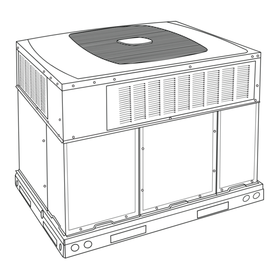
1
Fig. 1 - - Unit 677D- -- -A
. . . . . . . . . . . . . . . . . . . . . . . . . . . . . .
. . . . . . . . . . . . . . . . . . . . . . . . . . . . . . . . . . . . .
. . . . . . . . . . . . . . . . . . . . . . . . . . . . .
. . . . . . . . . . . . . . . . . . . .
. . . . . . . . . . . . . . . . . . . . . . . . . . . . . . . .
. . . . . . . . . . . . . . . . . . . . . . . . . . . . . .
. . . . . . . . . . . . . . . . . . . . . . . . . . . .
. . . . . . . . . . . . . . . . . . . . . . . . . . . . . . . . . . .
. . . . . . . . . . . . . . . . . . . . . . . . . . . . . . . . . . . .
. . . . . . . . . . . . . . . . . . . . . . . . . . . .
. . . . . . . . . . . . . . . . . . . . . . . . . . . . . . . . . . . . .
. . . . . . . . . . . . . . . . . . . . . . .
. . . . . . . . . . . . . . . . . . . . . . . . . . . . . . . . .
. . . . . . . . . . . . . . . . . . . . . . . . . . . . . . . . . . .
®
. . . . . . . . . . . . . . . . . . . . . . . . . . . . . . . . .
. . . . . . . . . . . . . . . . . . . . . . . . . . . .
. . . . . . . . . . . . . . . . . . . . . . . . . . . .
®
. . . . . . . . . . . . . . . . . . . . . . . . . . . . . . . .
. . . . . . . . . . . . . . . . . . . . . . . . . . . . . . . . . . . .
. . . . . . . . . . . . . . . . . . . . . . . . . . . . . . . . .
. . . . . . . . . . . . . . . . . . . . . . . . . .
. . . . . . . . . . . . . . .
. . . . . . . . . . . . . . . . . . . . . . . . . . . . . .
. . . . . . . . . . . . . . . . . . . . . . . . . . . . . . . . . . .
. . . . . . . . . . . . . . . . . . . . . . . .
. . . . . . . . . . . . . . . . . . . . . . . . . . . .
A09032
. . . . . . . . . . .
29
30
30
30
30
. .
30
30- -33
32
32
32
32
32
33
. . . . .
33
33
34
34
34
. . . . . . . . . . .
34
34
34
34
. . . . . . . .
34
34
35
35
. . . .
35
35
35
35
37
37
40
Advertisement
Table of Contents
Troubleshooting

Related Manuals for Bryant 677D--A


Summary of Contents for Bryant 677D--A
-
Page 1: Table Of Contents
677D- - - - A EVOLUTIONR 15 SEER SINGLE- - PACKAGED HYBRID HEATR DUAL FUEL SYSTEM WITH PURONr (R- - 410A) REFRIGERANT 2- - 5 NOMINAL TONS (SIZES 24- - 60) Installation Instructions CAUTION EQUIPMENT OPERATION HAZARD Failure to follow this caution may result in improper unit operation. -
Page 2: 677D
SAFETY CONSIDERATIONS INTRODUCTION The 677D- -- -A packaged HYBRID HEATR unit is a fully Improper installation, adjustment, alteration, service maintenance, self- -contained combination Category I gas heating/electric heat or use can cause explosion, fire, electrical shock, or other pump designed for outdoor installation (See Fig. 1). Standard units conditions which may cause death, personal injury, or property are shipped in a horizontal- -discharge configuration for installation damage. -
Page 3: Slab Mount
Rig and Place Unit spacer blocks (for easy alignment to existing curb) and gaskets for the perimeter seal and duct openings. This kit is WARNING used when existing curb is modified by removing outer horizontal flange. CAUTION PERSONAL INJURY OR PROPERTY DAMAGE HAZARD Failure to follow this warning could result in personal UNIT/STRUCTURAL DAMAGE HAZARD... - Page 4 HVAC unit HVAC unit basepan base rails Sealing Gasket Roofcurb Anchor screw Wood nailer* Flashing field Roofcurb* supplied Insulation (field supplied) Roofing material field supplied Cant strip field supplied SMALL CURB A09418 *Provided with roofcurb A09090 ROOF CURB DETAIL LARGE CURB A09415 A09419 CATALOG...
- Page 5 A09561 Fig. 5 - - 677D- -- -A24- -30 Unit Dimensions...
- Page 6 A09562 Fig. 6 - - 677D- -- -A36- -60 Unit Dimensions...
- Page 7 Table 1 – Physical Data - - Unit 677D- -- -A UNIT SIZE A24040 A30040 A30060 A36060 A36090 A42060 A42090 NOMINAL COOLING CAPACITY (ton) 2 ---1/2 2 ---1/2 3 ---1/2 3 ---1/2 NOMINAL HEATING CAPACITY (Btu) 40,000 40,000 60,000 60,000 90,000 60,000 90,000...
- Page 8 Table 1—Physical Data Con’t - - Unit 677D- -- -A UNIT SIZE A48090 A48115 A48130 A60090 A60115 A60130 NOMINAL COOLING CAPACITY (ton) NOMINAL HEATING CAPACITY (Btu) 90,000 115,000 130,000 90,000 115,000 130,000 SHIPPING WEIGHT (lb) (kg) Two- -Stage Scroll COMPRESSORS Quantity REFRIGERANT: PURON (R- - 410A) Quantity (lb)
-
Page 9: Select And Install Ductwork
CAUTION - NOTICE TO RIGGERS PRUDENCE - AVIS AUX MANIPULATEUR ACCESS PANELS MUST BE IN PLACE WHEN RIGGING. PANNEAUX D'ACCES DOIT ÊTRE EN PLACE POUR MANIPULATION. Use top skid as spreader bar. / Utiliser la palette du haut comme barre de répartition DUCTS MINIMUM HEIGHT: 36"... -
Page 10: Provide For Condensate Disposal
1. Open all electrical disconnects before starting any service If the installation requires draining the condensate water away from work. the unit, install a field- -supplied 2- -in. (51 mm) trap at the 2. Remove horizontal (metal) duct covers to access vertical condensate connection to ensure proper drainage. - Page 11 Table 2 – Maximum Gas Flow Capacity* LENGTH OF PIPE ft (m)† NOMINAL INTERNAL IRON PIPE DIAMETER SIZE (IN.) (IN.) (3.0) (6.1) (9.1) (12.1) (15.2) (18.3) (21.3) (24.4) (27.4) (30.5) (38.1) (45.7) (53.3) (61.0) .622 — — .824 1.049 1--- 1/4 1.380 1400 1--- 1/2...
-
Page 12: Install Electrical Connections
Install Electrical Connections GROUND SCREW (IN SPLICE BOX) WARNING GROUND LEAD ELECTRICAL SHOCK HAZARD SINGLE-PHASE Failure to follow this warning could result in personal CONNECTIONS injury or death. TO DISCONNECT PER NEC The unit cabinet must have an uninterrupted, unbroken electrical ground. -
Page 13: Accessory Installation
Option 1: Mounting Sensor to the Adjacent ACCESSORY INSTALLATION Building Structure A. Humidifier Connections The furnace control board terminal marked HUM is provided for 1. The recommended wall for mounting the sensor is the north low voltage (24- -vac) control of a humidifier. No humidistat is side of the building. - Page 14 HP/AC BOARD PACKAGE TWO BLACK WIRES TO CONNECT OAT SENSOR FURNACE BOARD A12248 Fig. 13 - - Control Plate A06357 Fig. 14 - - Control Voltage Wiring Connections...
-
Page 15: Pre- -Start- -Up
A09075 Fig. 15 - - Typical Installation PRE- -START- - UP Use the Start- -Up Checklist supplied at the end of this book and proceed as follows to inspect and prepare the unit for initial WARNING start- -up: 1. Remove all access panels. (See Fig. 25.) 2. -
Page 16: Unit Start- -Up And Troubleshooting
d. Make sure that air filter(s) is in place. 1. Check system transformer high- - and low- -voltage to be sure the system is powered. e. Make sure that condensate drain trap is filled with water to ensure proper drainage. 2. - Page 17 information provided below. Codes are listed in order of their STATUS CODE 15 - - BLOWER MOTOR LOCKOUT priority, highest to lowest. Though multiple faults can exist at any Indicates the blower failed to reach 250 RPM or the blower failed time, only the highest priority code will be displayed on STATUS to communicate within 30 seconds after being turned ON in two LED.
- Page 18 A10217C Fig. 17 - - Connection Wiring Schematic- -677D- -- -A Single Phase Gas Inputs 040, 060, 090 kBtu/hr...
- Page 19 A10217L Fig. 16 Cont. - - Ladder Wiring Schematic- -677D- -- -A Single Phase Gas Inputs 040, 060, 090 kBtu/hr...
- Page 20 A10219C Fig. 18 - - Connection Wiring Schematic- -677D- -- -A Single Phase Gas Inputs 115, 130 kBtu/hr...
- Page 21 A10219L Fig. 17 - - Ladder Wiring Schematic- -677D- -- -A Single Phase Gas Inputs 115, 130 kBtu/hr...
-
Page 22: Sequence Of Operation
UTILITY RELAY Liquid Line Solenoid UTILITY SIGNAL OPEN RELAY SUPPLIED BY UTILITY PROVIDER A05247 Fig. 19 - - 2- -Stage HP/AC Control Board STATUS CODE 31, 32 - - PRESSURE SWITCH OR RELAY STATUS CODE 45 - - CONTROL CIRCUITRY LOCKOUT DID NOT CLOSE OR REOPENED Auto reset after one hour lockout due to gas valve relay stuck open, Control relay may be defective. - Page 23 INDOOR AIRFLOW ADJUSTMENTS call for heat still exists after 10 minutes, the system will stage to second stage gas and run until the call for heat is satisfied. The nominal requested airflow for heat pump operations will be 350 cfm per ton of nominal cooling capacity as defined by unit NOTE: Heat stages are not shortened due to a 5 degree or higher size.
- Page 24 Table 4 – Heat Pump/Air Conditioner Board Status Codes AMBER OPERATION FAULT POSSIBLE CAUSE AND ACTION FLASH CODE Standby – no call for unit opera- On solid, None Normal operation. tion no flash Rapid, con- Unit being controlled by standard thermostat inputs instead of Standard Ther- Emergency Mode tinuous...
- Page 25 COMPRESSOR OPERATION stabilize.) When the compressor is operating in low stage, the modulating S In high stage and low stage, fan is on when outdoor coil temp > ring is deactivated, allowing two internal bypass ports to close off outdoor air temperature plus 25_F (13.4_C)or outdoor coil temp 33% of the scroll compression area so the system operates at part >...
- Page 26 the UI. When activated, the following sequence of operation will inducer motor will remain on for a 4- -second post- -purge occur. Reversing valve will energize and compressor will turn off period. The indoor blower and air cleaner terminal EAC- -1 for 30 seconds, then turn back on to complete defrost.
- Page 27 For installations above 2,000 ft (610 m), multiply the input by on REGULATOR COVER SCREW the rating plate by the derate multiplier in Table 5 for the correct input rate. PLASTIC ADJUST SCREW ON/OFF SWITCH IN CANADA: REGULATOR SPRING The input rating for altitudes from 2,000 (610 m) to 4,500 ft (1372 m) above sea level must be derated 10 percent by an authorized HIGH STAGE GAS PRESSURE REGULATOR...
- Page 28 supply air temperature, while ”EFFICIENCY” will b. Derate for altitude, if applicable. provide lower gas consumption. c. Return and supply ducts for excessive restrictions c. Make sure access panel is re- -installed on the unit. causing static pressures in excess of .5 IN. W.C. d.
-
Page 29: Check For Refrigerant Leaks
Table 6 – Heating Inputs GAS SUPPLY PRESSURE (IN. W.C.) MANIFOLD PRESSURE (IN. W.C.) HEATING INPUT (BTU/HR)* NUMBER OF NUMBER OF Natural Natural ORIFICES ORIFICES High Stage Low Stage High Stage Low Stage 40,000 26,000 13.0 3.2∼ 3.8 1.4 ∼ 2.0 60,000 39,000 13.0... -
Page 30: Refrigerant Charge
very minimal. If a substantial adjustment is indicated, an abnormal TO USE COOLING CHARGING CHARTS condition exists somewhere in the cooling system, such as Take the liquid line temperature and read the manifold pressure insufficient airflow across either coil or both coils. gauges. - Page 31 A09109 Fig. 24 - - Cooling Charging Table- -Subcooling Table 7 – ECM Wet Coil Pressure Drop (IN. W.C.) STANDARD CFM (SCFM) UNIT SIZE 1000 1100 1200 1300 1400 1500 1600 1700 1800 1900 2000 2100 0.005 0.007 0.010 0.012 0.015 –...
-
Page 32: Maintenance
MAINTENANCE 7. Inspect all accessories. Perform any service or maintenance to the accessories as recommended in the accessory To ensure continuing high performance, and to minimize the instructions. possibility of premature equipment failure, periodic maintenance Air Filter must be performed on this equipment. This HYBRID HEAT unit should be inspected at least once each year by a qualified service IMPORTANT: Never operate the unit without a suitable air filter person. -
Page 33: Inducer Pressure Switch
Inducer Pressure Switch 8. Partially slide the burner rack out of the unit (see Fig. 26 and 27). Remove ignitor and sensor wires at the burner as- Inspect pressure switch connections. Inspect pressure switch tube sembly. Remove wires to rollout switch. for cracks or restrictions. -
Page 34: Electrical Controls And Wiring
Loss- -of- -Charge (Low Pressure) Switch This switch is located on the liquid line and protects against low suction pressures caused by such events as loss of charge, low airflow across indoor coil, dirty filters, etc. It opens if the system pressure drops to about 20 psig. -
Page 35: Refrigerant
TROUBLESHOOTING REFRIGERANT WARNING LED DESCRIPTION LEDs built into Evolution control boards provide installer or service person information concerning operation and/or fault UNIT OPERATION, SAFETY condition of the unit controls and ECM motor. This information is ENVIRONMENTAL HAZARD also available at the system UI in text with basic troubleshooting Failure to follow this warning could result in personal instructions. - Page 36 CONTROL FAULT TEMPERATURE THERMISTORS If the HP/AC control board has failed, the control will flash the Thermistors are electronic devices which sense temperature. As the appropriate fault code (See Table 4). The control board should be temperature increases, the resistance decreases. Thermistors are replaced.
-
Page 37: Final Checks
FINAL CHECKS IMPORTANT: Before leaving job, be sure to do the following: 1. Ensure that all wiring is routed away from tubing and sheet metal edges to prevent rub- -through or wire pinching. 2. Ensure that all wiring and tubing is secure in unit before adding panels and covers. - Page 38 Table 9 – Troubleshooting Chart- -Heat Pump Operation SYMPTOM CAUSE REMEDY Power failure Call power company Fuse blown or circuit breaker tripped Replace fuse or reset circuit breaker Defective contactor, transformer, HP/AC control board, Replace component or high--pressure, loss--of--charge or low--pressure switch Insufficient line voltage Determine cause and correct...
- Page 39 Table 11 – Troubleshooting Chart- -Gas Furnace Operation SYMPTOM CAUSE REMEDY Water in gas line Drain. Install drip leg. Check power supply fuses, wiring or circuit No power to unit breaker. Check transformer. NOTE: Some transformers have internal over-- No 24--v power supply to control circuit current protection that requires a cool--down peri- od to reset.
-
Page 40: Start- -Up Checklist
{ Measured at liquid line leaving condenser. Catalog No. II677D---07 E2012 Bryant Heating & Cooling Systems D 7310 W. Morris St. D Indianapolis, IN 46231 Edition Date: 06/12 Manufacturer reserves the right to discontinue, or change at any time, specifications or designs without notice and without incurring obligations.
Need help?
Do you have a question about the 677D--A and is the answer not in the manual?
Questions and answers