Table of Contents
Advertisement
Quick Links
677E- - - - A and 677E- - - - B
PREFERREDt 15 SEER 2- - STAGE PACKAGED HYBRID HEATr
DUAL FUEL SYSTEM WITH PURONr (R- - 410A) REFRIGERANT
SINGLE AND THREE PHASE
2- - 5 NOMINAL TONS (SIZES 24- - 60)
IMPORTANT: Effective January 1, 2015, all split system and
packaged air conditioners must be installed pursuant to applicable
regional efficiency standards issued by the Department of Energy.
NOTE:
Read the entire instruction manual before starting the
installation.
NOTE:
Installer: Make sure the Owner's Manual and Service
Instructions are left with the unit after installation.
TABLE OF CONTENTS
. . . . . . . . . . . . . . . . . . . . . . . . . . . . . . . . . . .
. . . . . . . . . . . . . . . . . . . . . . . . . . . . . . . . . .
. . . . . . . . . . . . . . . . . . . . . . . . . . . . . . . . . . . .
. . . . . . . . . . . . . . . . . . . . . . . . . . . . . . . . .
. . . . . . . . . . . . . . . . . . . . . . . . . . . . . . .
. . . . . . . . . . . . . . . . . . . . . . . . . . . . . . . . . . . . . .
. . . . . . . . . . . . . . . . . . . . . . . . . . . . . . . . . . . . .
. . . . . . . . . . . . . . . . . . . . . . . . . . . .
. . . . . . . . . . . . . . . . . . . . . . . . . . . . . . . . .
. . . . . . . . . . . . . . . . . . . . . . . . . . . . . . . . .
. . . . . . . . . . . . . . . . . . . . . . . . . . . . . . . . . . . . . .
. . . . . . . . . . . . . . . . . . . . . . . . . . . .
. . . . . . . . . . . . . . . . . . . . . . . . . . . . . . . . . .
. . . . . . . . . . . . . . . . . . . . . . . . . . . . . . . . .
. . . . . . . . . . . . . . . . . . . . . . . . . . . .
. . . . . . . . . . . . . . . . . . . . . . . . . . . . . . . . . . . . .
. . . . . . . . . . . . . . . . . . . . . . . . . . . . .
. . . . . . . . . . . . . . . . . . . . . . . . . . .
. . . . . . . . . . . . . . . . . . . . . . . . . . . . . . . . . . .
. . . . . . . . . . . . . . . . . . . . . . . . . . . . . . . . . . . . .
. . . . . . . . . . . . . . . . . . . . . . . . . . .
. . . . . . . . . . . . . . . . . . . . . . . . . . . . . . . .
. . . . . . . . . . . . . . . . . . . . . . . . . . . . . . . .
. . . . . . . . . . . . . . . . . . . . . . . . . . . . .
. . . . . . . . . . . . . . . . . . . . . . . . . . . . . . .
. . . . . . . . . . . . . . . . . . . . . . . . . . . . . . . . .
. . . . . . . . . . . . . . . . . . . . . . . . . . . . . . . . .
. . . . . . . . . . . . . . . . . . . . . . . . . . . . . . . .
. . . . . . . . . . . . . . . . . . . . . . . . . . . . . . . . . . . . . .
Installation Instructions
. . . . . . . . . . . . . . . . . . . . . . . . .
. . . . . . . . . . . . . . . . .
. . . . . . . . . . . . . . . . . . . . . . . . . .
. . . . . . . . . . . . . . . . . . . . . . . .
. . . . . . . . . . . . . . . . . . . . . . . .
. . . . . . . . . . . . . .
. . . . . . . . . . . . . . . . . . . . . . .
. . . . . . . . . . . . . . . . . . . . . . . . . .
. . . . . . . . . . . . . . . . . . . . . . . . .
. . . . . . . . . . . . . . . .
. . . . . . . . . . . . . . . . . . . . . .
. . . . . . . . . . . . . . . . . . . . .
. . . . . . . . . . . . . . . .
. . . . . . . . . . . . . . . .
. . . . . . . . . . . .
. . . . . . . . . . . . .
. . . . . . . . . . . . . . . . . . . . .
. . . . . . . . . . . . . . . . . . . . . . . . .
PAGE
1
2
2- -16
2
2
2
2
2
3
3
3
3
3
3
12
12
13
14
14
15
15
15
15
. . . . . . . . . . . . . . . . . . . . . . . . . . . . . . . . . . . . . .
16
16
16
16
17- -29
SAFETY CONSIDERATIONS
17
Improper installation, adjustment, alteration, service maintenance,
17
or use can cause explosion, fire, electrical shock, or other
18
conditions which may cause death, personal injury, or property
18
damage. Consult a qualified installer, service agency, or your
18
distributor or branch for information or assistance. The qualified
19
installer or agency must use factory- -authorized kits or accessories
27
when modifying this product. Refer to the individual instructions
27
packaged with the kits or accessories when installing.
27
Follow all safety codes. Wear safety glasses, protective clothing,
27
and work gloves. Have a fire extinguisher available. Read these
27
instructions thoroughly and follow all warnings or cautions
27
included in literature and attached to the unit. consult local
27
building codes, the current editions of the National Fuel Gas Code
28
(NFGC) NFPA 54/ANSI Z223.1, and the National Electrical Code
28
(NEC) NFPA 70.
29
In Canada refer to the current editions of the National Standards of
60- -63
Canada CAN/CSA- -B149.1 and .2 Natural Gas and Propane
60
Installation codes, and Canadian Electrical Code CSA C22.1
60
1
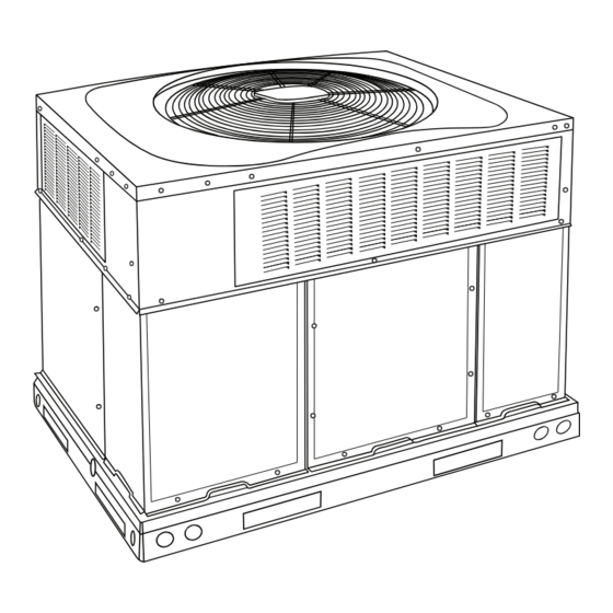
Fig. 1 - - Unit 677E
(Low NOx Model Available)
. . . . . . . . . . . . . .
. . . . . . . . . . . . . . . . . . . . . . . . . . . .
. . . . . . . . . . . . . . . . . . . . . . . . . . . . . . . . . . .
. . . . . . . . . . . . . . . . . . . . . . . . . . . . . . . . .
. . . . . . . . . . . . . . . . . . . . . . . . . . . . . . . . . . .
. . . . . . . . . . . . . . . . . . . . . . . . . . . .
. . . . . . . . . . . . . . . . . . . . . . . . . . . . . . . . . . .
. . . . . . . . . . . . . . . . . . . . .
. . . . . . . . . . . . . . . . . . . . . . . . . . . . . . .
. . . . . . . . . . . . . . . . . . . . . . . . . . . . . .
. . . . . . . . . . . . . . . . . . . . . . . . . . . . . . . . . . . .
. . . . . . . . . . . . . . . . . . . . . . . . . . . . . .
. . . . . . . . . . . . . . . . . . . . . . . . . . . .
A09033
61
61
61
61
61
61
. . . .
61
62
62
62
63
63
63
64
64
Advertisement
Table of Contents

Subscribe to Our Youtube Channel
Related Manuals for Bryant PREFERRED 677E B Series


Summary of Contents for Bryant PREFERRED 677E B Series
-
Page 1: Table Of Contents
677E- - - - A and 677E- - - - B PREFERREDt 15 SEER 2- - STAGE PACKAGED HYBRID HEATr DUAL FUEL SYSTEM WITH PURONr (R- - 410A) REFRIGERANT SINGLE AND THREE PHASE 2- - 5 NOMINAL TONS (SIZES 24- - 60) Installation Instructions IMPORTANT: Effective January 1, 2015, all split system and packaged air conditioners must be installed pursuant to applicable... -
Page 2: Introduction
and downflow configurations, and are factory shipped with all Recognize safety information. This is the safety- -alert symbol downflow duct openings covered. Units may be installed either on When you see this symbol on the unit and in instructions or manu- a rooftop or on a cement slab. -
Page 3: Slab Mount
used when existing curb is modified by removing outer 48- -in. (1219 mm) above the unit top. The maximum horizontal horizontal flange. extension of a partial overhang must not exceed 48- -in. (1219 mm). Do not place the unit where water, ice, or snow from an overhang WARNING or roof will damage or flood the unit. - Page 4 Lifting holes are provided in base rails as shown in Fig. 3 and 6. 1. Leave top shipping skid on the unit for use as a spreader bar to prevent the rigging straps from damaging the unit. If the skid is not available, use a spreader bar of sufficient length to protect the unit from damage.
- Page 5 A14647 Fig. 3 - - 677E- -- -A30 Unit Dimensions...
- Page 6 A14607 Fig. 4 - - 677E- -- -B24- -30 Unit Dimensions...
- Page 7 A14648 Fig. 5 - - 677E- -- -A36- -60 Unit Dimensions...
- Page 8 A14608 Fig. 6 - - 677E- -- -B36- -60 Unit Dimensions...
- Page 9 Dashed lines show cross support location for large basepan units. HVAC unit HVAC unit basepan base rails Sealing Gasket Roofcurb Anchor screw Wood nailer* Flashing field Roofcurb* supplied Insulation (field supplied) Roofing material field supplied Cant strip field supplied SMALL/COMMON CURB A09413 *Provided with roofcurb A09090...
- Page 10 CAUTION - NOTICE TO RIGGERS PRUDENCE - AVIS AUX MANIPULATEUR ACCESS PANELS MUST BE IN PLACE WHEN RIGGING. PANNEAUX D'ACCES DOIT ÊTRE EN PLACE POUR MANIPULATION. Use top skid as spreader bar. / Utiliser la palette du haut comme barre de répartition DUCTS MINIMUM HEIGHT: 36"...
- Page 11 Table 1 – Physical Data UNIT SIZE 24040 24060 30040 30060 36060 36090 42060 42090 NOMINAL CAPACITY (ton) 2 ---1/2 2 ---1/2 3 ---1/2 3 ---1/2 SHIPPING WEIGHT** lb. SHIPPING WEIGHT** (kg) Scroll COMPRESSORS Quantity REFRIGERANT (R --- 410A) 10.0 10.0 11.0 11.0...
-
Page 12: Connect Condensate Drain
Table 1—Physical Data Con’t UNIT SIZE 48090 48115 48130 60090 60115 60130 NOMINAL CAPACITY (ton) SHIPPING WEIGHT lb SHIPPING WEIGHT kg Scroll COMPRESSORS Quantity REFRIGERANT (R --- 410A) 12.0 12.0 12.0 14.8 14.8 14.8 Quantity lb Quantity (kg.) REFRIGERANT METERING DEVICE TXV, Indoor TXV ORIFICE ID in. -
Page 13: Install Gas Piping
Install the flue hood as follows: Grade all horizontal runs downward to risers. Use risers to connect to heating section and to meter. 1. This installation must conform with local building codes and with NFPA 54/ANSI Z223.1 National Fuel Gas Code 2. -
Page 14: Install Duct Connections
tion, and only the piece over the downshot knockout needs WARNING to be removed. Discard insulation. 4. To remove the downshot (plastic) knockouts for both sup- FIRE OR EXPLOSION HAZARD ply and returns, break front and right side connecting tabs with a screwdriver and hammer. -
Page 15: Install Electrical Connections
5. Size all ductwork for maximum required airflow (either codes for maximum fuse/circuit breaker size and minimum circuit heating or cooling) for unit being installed. Avoid abrupt amps (ampacity) for wire sizing. duct size increases or decreases or performance may be The field- -supplied disconnect switch box may be mounted on the affected. -
Page 16: Standard Connection
Standard Connection “balance point”, the heat pump will not be allowed to operate (i.e. locked out), and the gas furnace will be used to satisfy the indoor Run the low- -voltage leads from the thermostat, through the inlet temperature. There are three separate concepts which are related to hole, and into unit low- -voltage splice box. -
Page 17: Start- -Up
Use the Start- -Up Checklist supplied at the end of this book and 1. Locate leak and make sure that refrigerant system pressure proceed as follows to inspect and prepare the unit for initial has been relieved and reclaimed from both high- - and start- -up: low- -pressure ports. -
Page 18: Check Heating Control
IN THE U.S.A.: BURNER FLAME The input rating for altitudes above 2,000 ft (610 m) must be reduced by 4% for each 1,000 ft (305 m) above see level. BURNER For installations below 2,000 ft (610 m), refer to the unit rating plate. -
Page 19: Check Burner Flame
If the desired gas input is 115,000 Btuh, only a minor change in the REGULATOR COVER SCREW manifold pressure is required. PLASTIC ADJUST SCREW Observe manifold pressure(s) and proceed as follows to adjust gas ON/OFF SWITCH input(s): REGULATOR SPRING 1. Remove regulator cover screw(s) over plastic adjustment 1/2˝... - Page 20 Table 4 – Natural Gas Orifice Sizes and Manifold Pressure 208/230VAC Models ALTITUDE OF INSTALLATION (FT. [m] ABOVE SEA LEVEL) U.S.A.* Nameplate Input, 2001 to 0 to 2000 3001 to 4000 4001 to 5000 5001 to 6000 High Stage 3000* [0 to 610] [915 to 1219] [1220 to 1524]...
- Page 21 A14623 Fig. 16 - - 208/230- -1- -60 Connection Wiring Diagram...
- Page 22 A14624 Fig. 16 Cont. - - 208/230- -1- -60 Ladder Wiring Diagram...
- Page 23 A14619 Fig. 17 - - 208/230- -3- -60 Connection Wiring Diagram Gas Inputs 40, 60, 90 KBtu/hr...
- Page 24 A14620 Fig. 17 Cont. - - 208/230- -3- -60 Ladder Wiring Diagram Gas Inputs 40, 60, 90 KBtu/hr...
- Page 25 A14621 Fig. 18 - - 208/230- -3- -60 Connection Wiring Diagram Gas Inputs 115, 130...
- Page 26 A14622 Fig. 18 Cont. - - 208/230- -3- -60 Ladder Wiring Diagram Gas Inputs 115, 130...
-
Page 27: Normal Operation
Normal Operation Table 6 – LED Indications STATUS CODE LED INDICATION An LED (light- -emitting diode) indicator is provided on the Normal Operation integrated gas unit controller (IGC) to monitor operation. The IGC No Power or Hardware Failure is located by removing the control access panel (see Fig. 21). Check Fuse, Low Voltage Circuit 1 Flash During normal operation, the LED is continuously on (See Table 6... -
Page 28: Checking & Adjusting Refrigerant Charge
Indoor Airflow and Airflow Adjustments 3- -phase power lead orientation. If not corrected within 5 minutes, the internal protector will shut off the compressor. The 3- -phase CAUTION power leads to the unit must be reversed to correct rotation. When turning backwards, the difference between compressor suction and discharge pressures will be minimal. -
Page 29: Cooling Sequence Of Operation
Using the Same Fan Speed for More than One Mode: Some fan Table 8 – Color Coding for Indoor Fan Motor Leads speeds are ideal for more than one mode of operation. It is Black = High Speed permissible to use a field- -supplied jumper wire to connect one Orange = Med --- High Speed speed tap wire to two or more speed connections on the ignition board (IGC). - Page 30 L2 HIGH LOW C 1 1 D 1 4 D 1 2 D 2 6 D 1 3 D 1 9 D 2 8 D 2 0 R 5 4 R 5 5 R 6 7 D 1 8 R 6 6 R 5 7 R 6 8 D 1 7...
-
Page 60: Maintenance
MAINTENANCE 3. Inspect blower motor and wheel for cleanliness at the beginning of each heating and cooling season. Clean when To ensure continuing high performance and to minimize the necessary. For first heating and cooling season, inspect possibility of premature equipment failure, periodic maintenance blower wheel bi- -monthly to determine proper cleaning must be performed on this equipment. -
Page 61: Induced Draft (Combustion Air) Blower
f. Connect 5 pin plug and 4 pin plug to indoor blower 6. Remove wires connected to gas valve. Mark each wire. motor. 7. Remove the mounting screw that attaches the burner rack to g. Reinstall blower access panel (see Fig. 21). the unit base (See Fig. -
Page 62: Outdoor Fan
Outdoor Fan CAUTION UNIT OPERATION HAZARD Failure to follow this caution may result in damage to unit components. Keep the condenser fan free from all obstructions to ensure proper cooling operation. Never place articles on top of the unit. 1. Remove 6 screws holding outdoor grille and motor to top cover. -
Page 63: Gas Input
FAN GRILLE MOTOR MOTOR SHAFT A08505 MAX DISTANCE BETWEEN TOP OF FAN GRILLE AND BOTTOM OF FAN BLADE “A” SIZE Fig. 24 - - Fan Blade Position Gas Input Puron Items Metering Device (Thermostatic Expansion Valve & The gas input does not require checking unless improper heating performance is suspected. -
Page 64: Troubleshooting
High pressure may be caused by a dirty outdoor coil, failed fan Compressor Oil motor, or outdoor air recirculation. To check switch: The Copeland scroll compressor uses 3MAF POE oil. If additional 1. Turn off all power to unit. oil is needed, use Uniqema RL32- -3MAF. If this oil is not available, use Copeland Ultra 32 CC or Mobil Arctic EAL22 CC. - Page 65 Speedup Quiet Defrost interval Pins Shift DIP switches A08020 Fig. 26 - - Defrost Control...
- Page 66 C99097 Fig. 27 - - Refrigerant Circuit INDOOR COIL OUTDOOR COIL TXV in Metering Position HP S Bypass Position LEGEND HPS – High Pressure Switch LCS – Loss of Charge Switch Accurater ® Metering De vice Arrow indicates direction of flo w C03011 Fig.
- Page 67 INDOOR COIL OUTDOOR COIL TXV in Bypass Position HP S Metering Position LEGEND HPS – High Pressure Switch LCS – Loss of Charge Switch Accurater ® Metering De vice Arrow indicates direction of flo w C03012 Fig. 29 - - Typical Heat Pump Operation, Heating Mode...
- Page 68 PURONR (R- -410A) QUICK REFERENCE GUIDE S Puron refrigerant operates at 50- -70 percent higher pressures than R- -22. Be sure that servicing equipment and replacement components are designed to operate with Puron S Puron refrigerant cylinders are rose colored. S Recovery cylinder service pressure rating must be 400 psig, DOT 4BA400 or DOT BW400.
- Page 69 Table 15 – Troubleshooting Chart SYMPTOM CAUSE REMEDY Power failure Call power company Fuse blown or circuit breaker tripped Replace fuse or reset circuit breaker Defective contactor, transformer, or high--pressure, Replace component loss--of--charge or low--pressure switch Compressor and condenser fan will not start. Insufficient line voltage Determine cause and correct Incorrect or faulty wiring...
- Page 70 Table 16 – Troubleshooting Guide–Heating SYMPTOM CAUSE REMEDY Water in gas line Drain. Install drip leg. No power to furnace Check power supply fuses, wiring or circuit breaker. Check transformer. No 24--v power supply to control circuit NOTE: Some transformers have internal over--current protection that requires a cool--down period to reset.
- Page 71 START- -UP CHECKLIST (Remove and Store in Job Files) I. PRELIMINARY INFORMATION MODEL NO.: SERIAL NO.: DATE: TECHNICIAN: II. PRESTART- -UP (Insert check mark in box as each item is completed) ( ) VERIFY THAT ALL PACKING MATERIALS HAVE BEEN REMOVED FROM UNIT ( ) REMOVE ALL SHIPPING HOLD DOWN BOLTS AND BRACKETS PER INSTALLATION INSTRUCTIONS ( ) CHECK ALL ELECTRICAL CONNECTIONS AND TERMINALS FOR TIGHTNESS ( ) CHECK GAS PIPING FOR LEAKS (WHERE APPLICABLE)
- Page 72 Catalog No. II677E ---03 E2015 Bryant Heating & Cooling Systems D 7310 W. Morris St. D Indianapolis, IN 46231 Edition Date: 03/15 Manufacturer reserves the right to discontinue, or change at any time, specifications or designs without notice and without incurring obligations.
Need help?
Do you have a question about the PREFERRED 677E B Series and is the answer not in the manual?
Questions and answers