
Related Manuals for McIntosh MC2200


Summary of Contents for McIntosh MC2200
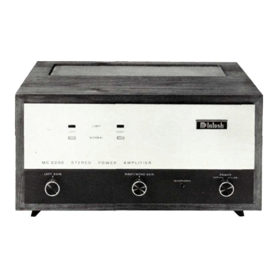
- Page 1 THE MclNTOSH MC 2200 SOLID STATE STEREO POWER AMPLIFIER Reading Time: 29 Minutes Price $1.25...
-
Page 3: Table Of Contents
Your MC 2200 Stereo Power Amplifier will give you many years of pleasant and satisfactory performance. If you have any questions, please contact: Contents CUSTOMER SERVICE Mclntosh Laboratory Inc. SERVICE 2 Chambers Street Binghamton, New York 13903 INSTALLATION Phone: 607-723-3512 HOW TO CONNECT FRONT PANEL INFORMATION WARNING: TO PREVENT FIRE OR SHOCK... -
Page 4: Installation
so be sure that the panel and its mounting can also handle the weight. INSTALLATION IN MclNTOSH CABINET Remove the instrument and hardware package from the carton. Remove the MC 2200 from its plastic bag and place it upside down on the shipping pallet; unscrew the four plastic feet from the bottom of the chassis. - Page 5 DEPTH REQUIRED 15". TOP OF SHELF & BOTTOM OF CUTOUT SHOULD COINCIDE. 6 9/16" SHELF 3" MOUNTING SCREWS DIFFERENCE BETWEEN SCREW LENGTH & TOTAL SHELF THICKNESS MUST NOT EXCEED 1/2" Fig. 2. Views showing mounting shelf in position. INSTALLATION PROCEDURE INSTALLATION IN A 19 INCH RACK •...
-
Page 6: How To Connect
INPUT available from the MC 2200, large diameter speaker leads must be used. Use lamp cord, bell wire, or wire with similar STEREO OR TWIN AMPLIFIER OPERATION type of insulation to connect the speakers to the amplifier. Use shielded cables to connect the signal from the pre- In all cases, the leads to and from the speaker should be amplifier or signal source to the power amplifier input. - Page 7 FOR MONOPHONIC CONSTANT VOLTAGE LINE each channel for the impedance desired. Full power will OPERATION be delivered to each properly connected speaker. For output When multiple speakers are to be connected to either or voltage of Connected for both outputs, the combined load impedance must be calcu- 25 volts 2 ohm output (mono) lated.
-
Page 10: Front Panel Information
Front Panel Information LEFT GAIN Use the LEFT GAIN control to adjust the volume in the left channel to the desired listening level. Turn the control clockwise to increase the volume. RIGHT/MONO GAIN Use the RIGHT/MONO GAIN control to adjust the volume in the right channel to the desired listening level. - Page 11 minates. A waveform comparator in the MC 2200 con- MC 2200. Plug dynamic headphones into the front panel stantly compares the amplifier input and output waveform. HEADPHONE jack. Adjust the front panel LEFT GAIN and Waveform difference of the output wave is converted to RIGHT/MONO GAIN control for comfortable headphone a voltage which is used as a control signal to "turn off"...
-
Page 12: Rear Panel Information
Rear Panel Information LEFT and RIGHT OUTPUT excellent channel separation of the MC 2200, it can fulfill For stereo operation, output impedances of 1, 2, 4 and all of these functions. When the instrument is properly con- nected the MODE switch is used to select the method of 8 ohms have been provided on a secure, screw type barrier operation desired. -
Page 13: Performance Limits And Ratings
Performance Limits and Ratings watts per channel from 20 Hz to 20,000 PERFORMANCE GUARANTEE Performance Limits are the maximum deviation from per- Hz, both channels operating fection permitted for a Mclntosh instrument We promise you that the MC 2200 you buy must be capable of per- MONO formance at or exceeding these limits or you get your 0.1% maximum harmonic distortion at any... -
Page 16: Technical Description
Technical Description INPUT AMPLIFIER The MC 2200 has transient free turn on and turn off Separate input amplifiers are used for the right and characteristics. This is because the output of the amplifier is switched by a heavy duty relay to the output auto trans- left channels. - Page 17 The input waveform and the output waveform are compared in an integrated circuit differential amplifier. Any differences, due to distortion of the output waveform, are converted to a control voltage. This control voltage is applied differentially to a high gain operational amplifier where it is amplified about 100 times.
- Page 20 MclNTOSH LABORATORY INC. 2 CHAMBERS ST., BINGHAMTON, N. Y. 13903 607-723-3512 Design subject to change without notice. Printed in U.S.A. 038-910...
Need help?
Do you have a question about the MC2200 and is the answer not in the manual?
Questions and answers