Asus M2N-VM DVI Manual
Hide thumbs
Also See for M2N-VM DVI:
- User manual (97 pages) ,
- User manual (100 pages) ,
- User manual (44 pages)
Table of Contents
Advertisement
Advertisement
Table of Contents

Related Manuals for Asus M2N-VM DVI


Summary of Contents for Asus M2N-VM DVI
- Page 1 M2N-VM DVI...
- Page 2 Product warranty or service will not be extended if: (1) the product is repaired, modified or altered, unless such repair, modification of alteration is authorized in writing by ASUS; or (2) the serial number of the product is defaced or missing.
-
Page 3: Table Of Contents
Contents Notices......................vi Safety.information..................vii About.this.guide..................viii M2N-VM DVI specifications summary............x Chapter.1:.Product.introduction 1.1. Welcome!..................1-2 1.2. Package.contents................1-2 1.3. Special.features................1-2 Product highlights ............1-2 1.3.1 1.3.2 Innovative ASUS features ..........1-5 1.4. - Page 4 Contents Chapter.2:.BIOS.setup 2.1. Managing.and.updating.your.BIOS..........2-2 2.1.1 Creating a bootable floppy disk ........2-3 2.1.2 ASUS EZ Flash 2 utility ........... 2-4 2.1.3 AFUDOS utility ..............2-5 2.1.4 ASUS CrashFree BIOS 2 utility ........2-7 2.1.5 ASUS Update utility ............2-9 2.2.
- Page 5 2.6.2 Removable Drives ............2-38 2.6.3 Boot Settings Configuration .......... 2-39 2.6.4 Security ................. 2-40 2.7. Tools.menu.................. 2-42 2.7.1 ASUS EZ Flash 2 ............2-42 2.8. Exit.menu..................2-43 Chapter.3:.Software.support 3.1. Installing.an.operating.system............ 3-2 3.2. Support.CD.information............... 3-2 3.2.1 Running the support CD ..........3-2 3.2.2...
-
Page 6: Notices
Notices Federal.Communications.Commission.Statement This device complies with Part 15 of the FCC Rules. Operation is subject to the following two conditions: • This device may not cause harmful interference, and • This device must accept any interference received including interference that may cause undesired operation. -
Page 7: Safety.information
Safety information Electrical.safety • To prevent electrical shock hazard, disconnect the power cable from the electrical outlet before relocating the system. • When adding or removing devices to or from the system, ensure that the power cables for the devices are unplugged before the signal cables are connected. If possible, disconnect all power cables from the existing system before you add a device. -
Page 8: About.this.guide
Refer to the following sources for additional information and for product and software updates. ASUS.websites The ASUS website provides updated information on ASUS hardware and software products. Refer to the ASUS contact information. Optional.documentation Your product package may include optional documentation, such as warranty flyers, that may have been added by your dealer. - Page 9 Conventions.used.in.this.guide To make sure that you perform certain tasks properly, take note of the following symbols used throughout this manual. DANGER/WARNING: Information to prevent injury to yourself when trying to complete a task. CAUTION: Information to prevent damage to the components when trying to complete a task.
-
Page 10: M2N-Vm Dvi Specifications Summary
M2N-VM DVI specifications summary CPU. Support AMD socket AM2 for AMD Athlon™ 64FX/ Athlon™ 64 X2/Athlon™ 64/Sempron processors AMD64 architecture enables simultaneous 32-bit and 64-bit computing Supports AMD Cool ‘n’ Quiet™ Technology Chipset ® ® Nvidia GeForce 7050PV/nForce 630A System.bus... - Page 11 M2N-VM DVI specifications summary BIOS.features 8 Mb Flash ROM, AMI BIOS, PnP, DMI2.0, WfM2.0, SM BIOS 2.4 Rear.panel.I/O 1 x LAN (RJ-45) port 4 x USB 2.0/1.1 ports 1 x VGA Out port 1 x DVI port 1 x PS/2 keyboard port...
- Page 13 This chapter describes the motherboard features and the new technologies it supports. Product introduction...
-
Page 14: Chapter.1:.Product.introduction
® The motherboard delivers a host of new features and latest technologies, making it another standout in the long line of ASUS quality motherboards! Before you start installing the motherboard, and hardware devices on it, check the items in your package with the list below. - Page 15 HDCP circuitry, and integration with leading HD movie software players. Dual.channel.DDR2.800..DDR2 800 memory provides great performance for 3D graphics and other memory demanding applications on next generation memory technology. See page 1-13 for details. ASUS M2N-VM DVI...
- Page 16 PCI.Express™.interface.. The motherboard fully supports PCI Express, the latest I/O interconnect technology that speeds up the PCI bus. PCI Express features point-to-point serial interconnections between devices and allows higher clockspeeds by carrying data in packets. This high speed interface is software compatible with existing PCI specifications.
-
Page 17: Innovative Asus Features
Innovative.ASUS.features. ASUS Q-Fan technology ..ASUS Q-Fan technology intelligently adjusts CPU fan speeds according to system loading to ensure quiet, cool and efficient operation. See page 2-37 for details. ASUS.CrashFree.BIOS.2.. This feature allows you to restore the original BIOS data from the support CD in case when the BIOS codes and data are corrupted. -
Page 18: Before.you.proceed
ON, in sleep mode, or in soft-off mode. This is a reminder that you should shut down the system and unplug the power cable before removing or plugging in any motherboard component. The illustration below shows the location of the onboard LED. M2N-VM DVI Chapter 1: Product introduction... -
Page 19: Motherboard.overview
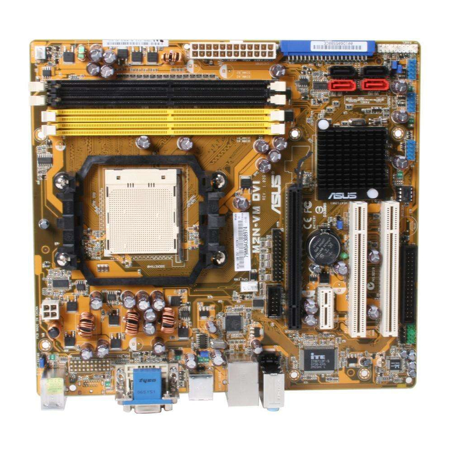
Motherboard overview 1.5.1. Motherboard.layout Lithium Cell CLRTC ASUS M2N-VM DVI... -
Page 20: Placement Direction
1.5.3. Screw.holes Place six (6) screws into the holes indicated by circles to secure the motherboard to the chassis. Do not overtighten the screws! Doing so can damage the motherboard. Place.this.side.towards. the.rear.of.the.chassis M2N-VM DVI Chapter 1: Product introduction... -
Page 21: Central.processing.unit.(Cpu)
Unlock the socket by pressing the lever sideways, then lift it up to a 90°-100° angle. Socket.lever Make sure that the socket lever is lifted up to 90°-100° angle, otherwise the CPU does not fit in completely. ASUS M2N-VM DVI... - Page 22 Connect the CPU fan cable to the CPU_FAN connector on the motherboard. M2N-VM DVI Do not forget to connect the CPU fan connector! Hardware monitoring errors can occur if you fail to plug this connector.
-
Page 23: Installing The Heatsink And Fan
Retention.bracket.lock Your boxed CPU heatsink and fan assembly should come with installation instructions for the CPU, heatsink, and the retention mechanism. If the instructions in this section do not match the CPU documentation, follow the latter. ASUS M2N-VM DVI 1-11... - Page 24 Attach one end of the retention bracket to the retention module base. Align the other end of the retention bracket (near the retention bracket lock) to the retention module base. A clicking sound denotes that the retention bracket is in place. Make sure that the fan and heatsink assembly perfectly fits the retention mechanism module...
-
Page 25: System.memory
You may install 256 MB, 512 MB, 1 GB, and 2 GB unbuffered ECC/non-ECC DDR2 DIMMs into the DIMM sockets. Recommended memory configurations Sockets Mode DIMM_A1 DIMM_B1 DIMM_A2 DIMM_B2 – Populated – – Single-Channel Populated – – – Dual-channel.(1) Populated Populated – – Dual-channel.(2) Populated Populated Populated Populated ASUS M2N-VM DVI 1-13... - Page 26 • When using only one memory module, start installing the DDR2 DIMM from slot DIMM_A1 or DIMM_B1 for better overclocking capability. • For dual-channel configuration (2), you may: install identical DIMMs in all four sockets OR install identical DIMM pair in DIMM_A1 and DIMM_B1 (yellow sockets) and another identical DIMM pair in DIMM_A2 and DIMM_B2 (black sockets) •...
- Page 27 Apacer AU01GE667C5KBGC Apacer AM4B5708MIJS7E0627B • • 512MB ADATA M20EL5G3H3160B1C0Z Elpida E5108AE-6E-E • • VDATA M2GVD5G3I4176I1C52 VDATA VD29608A8A-3EG20641 • • 512MB PSC AL6E8E63J-6E1 A3R12E3JFF717B9A00 • • AL7E8E63B-6E1K A3R12E3GEF637BLC5N • • 512MB Nanya NT512T64U88A1BY-3C Nanya NT5TU64M8AE-3C • • ASUS M2N-VM DVI 1-15...
- Page 28 Dual-channel memory configuration Supports 4 modules inserted into both the yellow slots and the black slots as two pairs of Dual-channel memory configuration Visit the ASUS website for the latest DDR2 DIMM modules for this motherboard. 1-16 Chapter 1: Product introduction...
-
Page 29: Installing A Dimm
DIMM. DDR2.DIMM.notch Support the DIMM lightly with your fingers when pressing the retaining clips. The DIMM might get damaged when it flips out with extra force. Remove the DIMM from the socket. ASUS M2N-VM DVI 1-17... -
Page 30: Expansion.slots
Expansion slots In the future, you may need to install expansion cards. The following sub-sections describe the slots and the expansion cards that they support. Make sure to unplug the power cord before adding or removing expansion cards. Failure to do so may cause you physical injury and damage motherboard components. -
Page 31: Interrupt Assignments
When using PCI cards on shared slots, ensure that the drivers support “Share IRQ” or that the cards do not need IRQ assignments; otherwise, conflicts will arise between the two PCI groups, making the system unstable and the card inoperable. ASUS M2N-VM DVI 1-19... -
Page 32: Pci Slots
1.8.3. PCI.slots The PCI slots support cards such as a LAN card, SCSI card, USB card, and other cards that comply with PCI specifications. The figure shows a LAN card installed on a PCI slot. 1.8.4. PCI.Express.x1.slot This motherboard supports PCI Express x1 network cards, SCSI cards and other cards that comply with the PCI Express specifications. -
Page 33: Jumpers
Normal Clear RTC (Default) M2N-VM DVI Clear RTC RAM You do not need to clear the RTC when the system hangs due to overclocking. For system failure due to overclocking, use the C.P.R. (CPU Parameter Recall) feature. Shut down and reboot the system so the BIOS can automatically reset parameter settings to default values. - Page 34 The USBPW1-4 jumpers are for the rear USB ports. The USBPW5-8 and USBPW910 jumpers are for the internal USB connectors that you can connect to additional USB ports. M2N-VM DVI • The USB device wake-up feature requires a power supply that can provide 500mA on the +5VSB lead for each USB port;...
-
Page 35: 1.10 Connectors
LAN (RJ-45) port. This port allows Gigabit connection to a Local Area Network (LAN) through a network hub. LAN.port.LED.indications ACT/LINK. SPEED. Activity/Link.LED Speed.LED Status Description Status Description No link 10 Mbps connection ORANGE Linked ORANGE 100 Mbps connection BLINKING Data activity GREEN 1 Gbps connection LAN.port ASUS M2N-VM DVI 1-23... - Page 36 Line In port (light blue). This port connects a tape, CD, DVD player, or other audio sources. Line Out port (lime). This port connects a headphone or a speaker. In 4- channel/ 6-channel configuration, the function of this port becomes Front Speaker Out.
-
Page 37: Internal Connectors
By default, the pins labeled “Chassis Signal” and “Ground” are shorted with a jumper cap. Remove the jumper caps only when you intend to use the chassis intrusion detection feature. ASUS M2N-VM DVI 1-25... - Page 38 IDE.connectors.(40-1.pin.PRI_IDE) The onboard IDE connector is for an Ultra DMA 133/100/66 signal cable. There are three connectors on each Ultra DMA 133/100/66 signal cable: blue, black, and gray. Connect the blue connector to the motherboard’s IDE connector, then select one of the following modes to configure your device(s). Drive jumper setting Mode.of.
- Page 39 RAID 10, and JBOD, refer to the RAID manual in the support CD. • If you intend to create a Serial ATA RAID set using these connectors, set the.onboard.SATA.Type item in the BIOS to [RAID controller]. See the page 2-16 for details. ASUS M2N-VM DVI 1-27...
- Page 40 These are not jumpers! DO NOT place jumper caps on the fan connectors. Only CPU Fan supports Q-Fan. M2N-VM DVI Digital.audio.connector.(4-1.pin.SPDIF_OUT) This connector is for an additional Sony/Philips Digital Interface (S/PDIF) port(s).
- Page 41 Never connect a 1394 cable to the USB connectors. Doing so will damage the motherboard! The USB 2.0 module is purchased separately. Optical.drive.audio.in.connector.(4-pin.CD) These connectors allow you to receive stereo audio input from sound sources such as a CD-ROM, TV tuner, or MPEG card. M2N-VM DVI ASUS M2N-VM DVI 1-29...
- Page 42 The serial port bracket (COM1) is purchased separately. M2N-VM DVI 10.. Front.panel.audio.connector.(10-1.pin.AAFP) This connector is for a chassis-mounted front panel audio I/O module that supports either High Definition Audio or AC`97 audio standard.
- Page 43 The system may become unstable or may not boot up if the power is inadequate. • You must install a PSU with a higher power rating if you intend to install additional devices. ASUS M2N-VM DVI 1-31...
- Page 44 12.. LPT.connector The LPT (Line Printing Terminal) connector supports devices such as a printer. LPT standardizes as IEEE 1284, which is the parallel port interface on IBM PC-compatible computers. M2N-VM DVI 1-32 Chapter 1: Product introduction...
-
Page 45: System Panel Connector
BIOS settings. Pressing the power switch for more than four seconds while the system is ON turns the system OFF. • Reset button This 2-pin connector is for the chassis-mounted reset button for system reboot without turning off the system power. ASUS M2N-VM DVI 1-33... - Page 46 1-34 Chapter 1: Product introduction...
-
Page 47: Bios Setup
This chapter tells how to change the system settings through the BIOS Setup menus. Detailed descriptions of the BIOS parameters are also provided. BIOS setup... -
Page 48: Chapter.2:.Bios.setup
The following utilities allow you to manage and update the motherboard Basic Input/Output System (BIOS) setup. ASUS.EZ.Flash.2 (Updates the BIOS using a floppy disk, USB Flash, or the motherboard support CD during POST.) ASUS.AFUDOS (Updates the BIOS in DOS mode using a bootable floppy disk.) -
Page 49: Creating A Bootable Floppy Disk
® c. Right-click Floppy.Disk.Drive.then click Format to display the Format.3. 1/2.Floppy dialog box . d. Select the Create.an.MS-DOS.startup.disk check box. e. Click Start. Copy the original or the latest motherboard BIOS file to the bootable floppy disk. ASUS M2N-VM DVI... -
Page 50: Asus Ez Flash 2 Utility
2.1.2. ASUS.EZ.Flash.2.utility The ASUS EZ Flash 2 feature allows you to update the BIOS without having to go through the long process of booting from a floppy disk and using a DOS-based utility. The EZ Flash 2 utility is built-in the BIOS chip so it is accessible by pressing <Alt>... -
Page 51: Afudos Utility
Extension.name Press <Enter>. The utility copies the current BIOS file to the floppy disk. A:\>afudos /oOLDBIOS1.rom AMI Firmware Update Utility - Version 1.19(ASUS V2.07(03.11.24BB)) Copyright (C) 2002 American Megatrends, Inc. All rights reserved. Reading flash ..done Write to file..ok A:\>... -
Page 52: Updating The Bios File
Updating the BIOS file To update the BIOS file using the AFUDOS utility: Visit the ASUS website (www.asus.com) and download the latest BIOS file for the motherboard. Save the BIOS file to a bootable floppy disk. Write the BIOS filename on a piece of paper. You need to type the exact BIOS filename at the DOS prompt. -
Page 53: Asus Crashfree Bios 2 Utility
2.1.4. ASUS.CrashFree.BIOS.2.utility The ASUS CrashFree BIOS 2 is an auto recovery tool that allows you to restore the BIOS file when it fails or gets corrupted during the updating process. You can update a corrupted BIOS file using the motherboard support CD or the floppy disk that contains the updated BIOS file. - Page 54 Start flashing... Restart the system after the utility completes the updating process. The recovered BIOS may not be the latest BIOS version for this motherboard. Visit the ASUS website (www.asus.com) to download the latest BIOS file. Chapter 2: BIOS setup...
-
Page 55: Asus Update Utility
2.1.5. ASUS.Update.utility The ASUS Update is a utility that allows you to manage, save, and update the motherboard BIOS in Windows environment. The ASUS Update utility allows you ® • Save the current BIOS file • Download the latest BIOS file from the Internet •... - Page 56 Updating.the.BIOS.through.the.Internet To update the BIOS through the Internet: Launch the ASUS Update utility from the Windows desktop by clicking Start. ® >.Programs.>.ASUS.>.ASUSUpdate.>.ASUSUpdate. The ASUS Update main window appears. Select Update.BIOS.from. Select the ASUS FTP site nearest the.Internet.option from the you to avoid network traffic, or drop-down menu, then click Next.
- Page 57 Updating the BIOS through a BIOS file To update the BIOS through a BIOS file: Launch the ASUS Update utility from the Windows desktop by clicking Start ® >.Programs.>.ASUS.>.ASUSUpdate.>.ASUSUpdate. The ASUS Update main window appears.
-
Page 58: Bios.setup.program
The BIOS setup screens shown in this section are for reference purposes only, and may not exactly match what you see on your screen. • Visit the ASUS website (www.asus.com) to download the latest BIOS file for this motherboard. 2-12... -
Page 59: Bios Menu Screen
• The BIOS setup screens shown in this chapter are for reference purposes only, and may not exactly match what you see on your screen. • Visit the ASUS website (www.asus.com) to download the latest BIOS information. 2.2.3. Navigation.keys At the bottom right corner of a menu screen are the navigation keys for that particular menu. -
Page 60: Menu Items
Some of the navigation keys differ from one screen to another. 2.2.4. Menu.items The highlighted item on the menu bar displays the specific items for that menu. For example, selecting Main shows the Main menu items. The other items (Advanced, Power, Boot, and Exit) on the menu bar have their respective menu items. -
Page 61: Main.menu
System.Time.[xx:xx:xx] Allows you to set the system time. 2.3.2. System.Date.[Day.xx/xx/xxxx] Allows you to set the system date. 2.3.3. Legacy.Diskette.A.[1.44M,.3.5.in.] Sets the type of floppy drive installed. Configuration options: [Disabled] [720K , 3.5 in.] [1.44M, 3.5 in.] ASUS M2N-VM DVI 2-15... -
Page 62: Ide Configuration
2.3.4. IDE Configuration The items in this menu allow you to set or change the configurations for the IDE devices installed in the system. Select an item then press <Enter> if you wish to configure the item. IDE Configuration Onboard IDE Controller [Enabled] Serial-ATA Devices [Enabled]... -
Page 63: Primary Ide Master/Slave
When set to [Disabled], the data transfer from and to the device occurs one sector at a time. Configuration options: [Disabled] [Auto] ASUS M2N-VM DVI 2-17... - Page 64 PIO.Mode.[Auto] Selects the PIO mode. Configuration options: [Auto] [0] [1] [2] [3] [4] DMA.Mode.[Auto] Selects the DMA mode. Configuration options: [Auto] SMART.Monitoring.[Auto] Sets the Smart Monitoring, Analysis, and Reporting Technology. Configuration options: [Auto] [Disabled] [Enabled] 32Bit.Data.Transfer.[Enabled] Enables or disables 32-bit data transfer. Configuration options: [Disabled] [Enabled] 2-18 Chapter 2: BIOS setup...
-
Page 65: Sata 1-4
When set to [Disabled], the data transfer from and to the device occurs one sector at a time. Configuration options: [Disabled] [Auto] PIO.Mode.[Auto] Selects the PIO mode. Configuration options: [Auto] [0] [1] [2] [3] [4] ASUS M2N-VM DVI 2-19... -
Page 66: System Information
DMA.Mode.[Auto] Selects the DMA mode. Configuration options: [Auto] [SWDMA0] [SWDMA1] [SWDMA2] [MWDMA0] [MWDMA1] [MWDMA2] [UDMA0] [UDMA1] [UDMA2] [UDMA3] [UDMA4] [UDMA5] [UDMA6] SMART.Monitoring.[Auto] Sets the Smart Monitoring, Analysis, and Reporting Technology. Configuration options: [Auto] [Disabled] [Enabled] 32Bit.Data.Transfer.[Enabled] Enables or disables 32-bit data transfer. Configuration options: [Disabled] [Enabled] 2.3.7. -
Page 67: Advanced.menu
[Auto] - allows you to set overclocking parameters automatically. [MANUAL] - allows you to individually set overclocking parameters. [Standard] - loads the standard settings for the system. [Overclock Profile] - loads overclocking profiles with optimal parameters for stability when overclocking. ASUS M2N-VM DVI 2-21... - Page 68 The following item appears only when the AI Overclocking item is set to [MANUAL]. CPU.Frequency.[200] Displays the frequency sent by the clock generator to the system bus and PCI bus. The value of this item is auto-detected by the BIOS. Use the < > and < > keys to adjust the CPU frequency.
-
Page 69: Cpu Configuration
Secure.Virtual.Machine.[Enabled] Allows you to enable or disable the AMD Secure Virtual Machine. Configuration options: [Disabled] [Enabled] Cool‘n’Quiet [Enabled] Allows you to enable or disable the generation of ACPI_PPC, _PSS, and _PCT objects. Configuration options: [Disabled] [Enabled] ASUS M2N-VM DVI 2-23... - Page 70 AMD Overlooking Configuration AMD Overlooking Configuration Configure CPU Frequence. Processor Frequency Multiplier [Auto] Processor Voltage [Auto] Processor.Frequency.Multiplier.[Auto] Allows you to select Processor frequency. Configuration options: [Auto] [x5.0 1000 MHz] [x6.0 1200 MHz] [x7.0 1400 MHz] [x8.0 1600 MHz] [x9.0 1800 MHz] [x10.0 2000 MHz] Processor.Voltage.[Auto] Allows you to select the Processor voltage or set it to auto for safe mode.
-
Page 71: Chipset
Memory Options & Advanced Chipset Setting Information WARNING: Setting wrong values in below sections may cause system to malfunction. Memory Controller Southbridge Configuration Hyper Transport Configuration Memory.Controller Memory Controller Memory Configuration ECC Configuration Power Down Control [Auto] ASUS M2N-VM DVI 2-25... - Page 72 Memory Configuration Select the DRAM Memory Configuration Frequency programing Memory Setting: 266MHz-4.0-4-4-11-2T method. If Auto, the DRAM speed will Memclock Mode [Auto] be based on SPDs. CAS Latency (CL) [Auto] If Limit, the DRAM TRCD [Auto] spe will not exceed [Auto] the specific value.
- Page 73 Configuration options: [Disabled] [Enabled] MemClk Tristate C3/ALTVID [Disabled] Enables or disables the MemClk Tristate C3/ALTVID. Configuration options: [Disabled] [Enabled] Memory Hole Remapping [Enabled] Enables or disables the memory remapping around memory hole. Configuration options: [Disabled] [Enabled] ASUS M2N-VM DVI 2-27...
-
Page 74: Ecc Configuration
ECC Configuration DRAM ECC allows ECC Configuration hardware to report and correct memory DRAM ECC Enable [Enabled] errors automatically 4-Bit ECC Mode [Disabled] maintaining system DRAM SCRUB REDIRECT [Disabled] integrity. DRAM BG Scrub [Disabled] L2 Cache BG Scrub [Disabled] Data Cache BG Scrub [Disabled] DRAM ECC Enable [Enabled] Enables or disables the DRAM ECC that allows the hardware to report and... -
Page 75: Southbridge Configuration
Configuration options: [Auto] [Disabled] OnBoard LAN Boot ROM [Disabled] Allows you to enable or disable the OnBoard LAN Boot ROM. Configuration options: [Enabled] [Disabled] SouthBridge.ACPI.HPET.TABLE.[Enabled] Allows you to enable or disable SouthBridge ACPI HPET TABLE. Configuration options: [Enabled] [Disabled] ASUS M2N-VM DVI 2-29... -
Page 76: Hyper Transport Configuration
Hyper Transport Configuration The sub-menu allows you to change the Hyper Transport settings. Hyper Transport Configuration SouthBridge to K8(CPU) frequency selection by CPU capability SB to K8(CPU) Freq Auto [Disabled] SB to K8(CPU) Frequency [1000 MHZ] SB to K8(CPU) LinkWidth 16 ] SB.to.K8(CPU).Freq.Auto.[Disabled] Enables or disables the CPU to automatically adjust Hyper Transport frequency. -
Page 77: Onboard Device Configuration
Allows you to select the Parallel Port base addresses. Configuration options: [Disabled] [378] [278] [3BC] Parallel.Port.Mode.[Normal] Allows you to select the Parallel Port mode. Configuration options: [Normal] [EPP] [ECP] [EPP+ECP] Parallel Port IRQ [IRQ7] Configuration options: [IRQ5] [IRQ7] ASUS M2N-VM DVI 2-31... -
Page 78: Pcipnp
2.4.5. PCI.PnP The PCI PnP menu items allow you to change the advanced settings for PCI/PnP devices. The menu includes setting IRQ and DMA channel resources for either PCI/PnP or legacy ISA devices, and setting the memory size block for legacy ISA devices. -
Page 79: Usb Configuration
(OS). Setting to Auto allows the system to detect the presence of USB devices at startup. If detected, the USB controller legacy mode is enabled. If no USB device is detected, the legacy USB support is disabled. Configuration options: [Disabled] [Enabled] [Auto] ASUS M2N-VM DVI 2-33... -
Page 80: Usb Mass Storage Device Configuration
USB.2.0.Controller.Mode.[HiSpeed] Allows you to configure the USB 2.0 controller in HiSpeed (480 Mbps) or Full Speed (12 Mbps). Configuration options: [Full Speed] [HiSpeed] BIOS.EHCI.Hand-Off.[Enabled].. Allows you to configure the BIOS EHCI Hand-Off. Configuration options: [Disabled] [Enabled] USB Mass Storage Device Configuration Number of seconds USB Mass Storage Device Configuration POST waits for the... -
Page 81: Power.menu
Allows you to enable or disable the Advanced Configuration and Power Interface (ACPI) support in the Application-Specific Integrated Circuit (ASIC). When set to Enabled, the ACPI APIC table pointer is included in the RSDT pointer list. Configuration options: [Disabled] [Enabled] ASUS M2N-VM DVI 2-35... -
Page 82: Apm Configuration
2.5.4 APM Configuration APM Configuration Go into On/Off or Suspend when Power Button Mode [On/Off] Power button is Restore on AC Power Loss [Power Off] pressed. Power On By PCI Device [Disabled] Power On By Ring [Disabled] Power On By PS/2 KB/MS [Disabled] Power On By RTC Alarm [Disabled]... -
Page 83: Hardware Monitor
The onboard hardware monitor automatically detects the voltage output through the onboard voltage regulators. Smart Q-Fan Function [Disabled] Allows you to enable or disable the ASUS Q-Fan feature that smartly adjusts the fan speeds for more efficient system operation. Configuration options: [Disabled] [Enabled]... -
Page 84: Boot.menu
Boot menu The Boot menu items allow you to change the system boot options. Select an item then press <Enter> to display the sub-menu. Specifies the Boot Boot settings Device Priority sequence. Boot Device Priority Removable Drives A virtual floopy disk Boot Settings Configuration drive (Floppy Drive Security... -
Page 85: Boot Settings Configuration
Full.Screen.Logo.[Enabled] This allows you to enable or disable the full screen logo display feature. Configuration options: [Disabled] [Enabled] Set this item to [Enabled] to use the ASUS MyLogo 2™ feature. Add.On.ROM.Display.Mode.[Force.BIOS] Sets the display mode for option ROM. Configuration options: [Force BIOS] [Keep Current] Bootup.Num-Lock.[On]... -
Page 86: Security
Interrupt.19.Capture.[Disabled] When set to [Enabled], this function allows the option ROMs to trap Interrupt 19. Configuration options: [Disabled] [Enabled] 2.6.4. Security The Security menu items allow you to change the system security settings. Select an item then press <Enter> to display the configuration options. Security Settings <Enter>... - Page 87 Password.Check.[Setup] When set to [Setup], BIOS checks for user password when accessing the Setup utility. When set to [Always], BIOS checks for user password both when accessing Setup and booting the system. Configuration options: [Setup] [Always] ASUS M2N-VM DVI 2-41...
-
Page 88: Tools.menu
1. NTFS format 2.7.1. ASUS.EZ.Flash.2 Allows you to run ASUS EZ Flash 2. When you press <Ok>, a confirmation message appears. Use the left/right arrow key to select between [Yes] or [No], then press <Ok> to confirm your choice. ASUSTek EZ Flash 2 BIOS ROM Utility V3.00... -
Page 89: Exit.menu
Setup menus. When you select this option or if you press <F5>, a confirmation window appears. Select OK to load default values. Select Exit & Save Changes or make other changes before saving the values to the non-volatile RAM. ASUS M2N-VM DVI 2-43... - Page 90 2-44 Chapter 2: BIOS setup...
-
Page 91: Software Support
This chapter describes the contents of the support CD that comes with the motherboard package. Software support... -
Page 92: Chapter.3:.Software.support
The contents of the support CD are subject to change at any time without notice. Visit the ASUS website(www.asus.com) for updates. 3.2.1. Running.the.support.CD Place the support CD to the optical drive. The CD automatically displays the Drivers menu if Autorun is enabled in your computer. -
Page 93: Drivers Menu
The drivers menu shows the available device drivers if the system detects installed devices. Install the necessary drivers to activate the devices. ASUS.InstAll.-.Drivers.Installation.Wizard Launches the ASUS InstallAll driver installation wizard. AMD Cool ‘n’ Quiet Driver Installs the AMD Cool ‘n’ Quiet driver. -
Page 94: Utilities Menu
This utility helps you keep your computer in healthy operating condition. ASUS.Update. The ASUS Update utility allows you to update the motherboard BIOS in a Windows environment. This utility requires an Internet connection either through a ®... - Page 95 You can also install the following utilities from the ASUS Superb Software Library CD. ADOBE.Acrobat.Reader.V7.0 Installs the Adobe® Acrobat® Reader that allows you to open, view, and print documents in Portable Document Format (PDF). Microsoft.DirectX.9.0c Installs the Microsoft® DirectX 9.0c driver. The Microsoft DirectX® 9.0c is a multimedia technology that enhances computer graphics and sound.
-
Page 96: Make Disk Menu
3.2.4. Make.Disk.menu The Make Disk menu allows you to make a RAID driver disk. Make.NVIDIA.RAID.Windows2000.Driver. Allows you to create an NVIDIA RAID Windows2000 bit Driver disk. Make.NVIDIA.RAID.WindowsXP.32/64.bit.Driver. Allows you to create an NVIDIA RAID WindowsXP 32/64 bit Driver disk. Make.NVIDIA.RAID.Windows.Vista32/64.bit.Driver. Allows you to create an NVIDIA RAID Windows Vista32/64 bit driver disk for Windows... -
Page 97: Asus Contact Information
3.2.6. ASUS.Contact.information Click the Contact tab to display the ASUS contact information. You can also find this information on the inside front cover of this user guide. 3.2.7. Other.information The icons on the top right corner of the screen give additional information on the motherboard and the contents of the support CD. - Page 98 Browse.this.CD Displays the support CD contents in graphical format. Technical.support.Form Displays the ASUS Technical Support Request Form that you have to fill out when requesting technical support. Filelist Displays the contents of the support CD and a brief description of each in text format.
Need help?
Do you have a question about the M2N-VM DVI and is the answer not in the manual?
Questions and answers