Table of Contents
Advertisement
Advertisement
Table of Contents

Related Manuals for Asus M2N68-VM


Summary of Contents for Asus M2N68-VM
- Page 1 M2N68-VM...
- Page 2 Product warranty or service will not be extended if: (1) the product is repaired, modified or altered, unless such repair, modification of alteration is authorized in writing by ASUS; or (2) the serial number of the product is defaced or missing.
-
Page 3: Table Of Contents
Contents Notices ......................vi Safety information ..................vii About this guide ..................viii M2N68-VM specifications summary ............x Chapter 1: Product introduction Welcome! ..................1-2 Package contents ................. 1-2 Special features ................1-2 1.3.1 Product highlights ............1-2 1.3.2 Innovative ASUS features ..........1-4 Before you proceed .............. - Page 4 Chapter 2: BIOS setup Managing and updating your BIOS ..........2-2 2.1.1 Creating a bootable floppy disk ........2-2 2.1.2 ASUS EZ Flash 2 utility ........... 2-4 2.1.3 AFUDOS utility ..............2-5 2.1.4 ASUS CrashFree BIOS 3 utility ........2-7 2.1.5 ASUS Update utility ............
- Page 5 Boot Device Priority ............2-36 2.6.2 Boot Settings Configuration .......... 2-37 2.6.3 Security ................. 2-38 Tools menu ................. 2-40 2.7.1 ASUS EZ Flash 2 ............2-40 2.7.2 Express Gate ..............2-41 2.7.3 AI NET 2................ 2-41 Exit menu ..................2-42 Chapter 3: Software support Installing an operating system ...........
-
Page 6: Notices
Notices Federal Communications Commission Statement This device complies with Part 15 of the FCC Rules. Operation is subject to the following two conditions: • This device may not cause harmful interference, and • This device must accept any interference received including interference that may cause undesired operation. -
Page 7: Safety Information
Safety information Electrical safety • To prevent electrical shock hazard, disconnect the power cable from the electrical outlet before relocating the system. • When adding or removing devices to or from the system, ensure that the power cables for the devices are unplugged before the signal cables are connected. If possible, disconnect all power cables from the existing system before you add a device. -
Page 8: About This Guide
Refer to the following sources for additional information and for product and software updates. ASUS websites The ASUS website provides updated information on ASUS hardware and software products. Refer to the ASUS contact information. Optional documentation Your product package may include optional documentation, such as warranty flyers, that may have been added by your dealer. -
Page 9: Conventions Used In This Guide
Conventions used in this guide To ensure that you perform certain tasks properly, take note of the following symbols used throughout this manual. DANGER/WARNING: Information to prevent injury to yourself when trying to complete a task. CAUTION: Information to prevent damage to the components when trying to complete a task. -
Page 10: M2N68-Vm Specifications Summary
M2N68-VM specifications summary Support AMD socket AM2 for AMD Athlon™ 64 FX / Athlon™ 64 X2 / Athlon™ 64 / Phenom / Phenom FX / Sempron / AM2+ processors AMD64 architecture enables simultaneous 32-bit and 64-bit computing Supports AMD Cool ‘n’ Quiet™ Technology... - Page 11 * The actual boot time is subject to hardware configurations and product models. ASUS Quiet Thermal Solution - ASUS Q-Fan ASUS EZ DIY - ASUS CrashFree BIOS 3 - ASUS EZ Flash 2 ASUS MyLogo 2™ Rear panel I/O 1 x LAN (RJ-45) port...
- Page 12 ASUS Overclocking SFS (Stepless Frequency Selection) from 200MHz to Features 300MHz at 1MHz increment Adjustable CPU Voltage at 0.025V increment ASUS C.P.R. (CPU Parameter Recall) Support DVD contents Device drivers ASUS PC Probe II ASUS Live Update utility Anti-virus software (OEM version)
-
Page 13: Chapter 1: Product Introduction
This chapter describes the motherboard features and the new technologies it supports. Product introduction... -
Page 14: Welcome
® The motherboard delivers a host of new features and latest technologies, making it another standout in the long line of ASUS quality motherboards! Before you start installing the motherboard, and hardware devices on it, check the items in your package with the list below. - Page 15 JBOD configurations for three SATA connectors and one External SATA connector. The External SATA port located at the back I/O provides smart setup and hot-plug functions. Easily backup photos, videos and other entermainment contents on external devices. ASUS M2N68-VM...
-
Page 16: Innovative Asus Features
See page 2-35 for details. ASUS CrashFree BIOS 3 The ASUS CrashFree BIOS 3 allows users to restore corrupted BIOS data from a USB flash disk containing the BIOS file. See page 2-7 for details. -
Page 17: Asus Mylogo 2
What’s more, the user-friendly picture manager lets you view your pictures without entering Windows at anytime! • The actual boot time depends on the system configuration. • ASUS Express Gate supports file uploading from SATA HDDs, ODDs and USB drive and downloading to USB drives only. ASUS M2N68-VM... -
Page 18: Before You Proceed
The illustration below shows the location of the onboard LED. SB_PWR M2N68-VM Standby Powered Power M2N68-VM Onboard LED Chapter 1: Product introduction... -
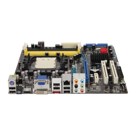
Page 19: Motherboard Overview
Motherboard overview 1.5.1 Motherboard layout ASUS M2N68-VM... -
Page 20: Placement Direction
Place eight (8) screws into the holes indicated by circles to secure the motherboard to the chassis. Do not overtighten the screws! Doing so can damage the motherboard. Place this side towards the rear of the chassis M2N68-VM Chapter 1: Product introduction... -
Page 21: Central Processing Unit (Cpu)
1.6.1 Installing the CPU To install a CPU. Locate the CPU socket on the motherboard. M2N68-VM M2N68-VM CPU Socket AM2+ Unlock the socket by pressing the lever sideways, then lift it up to a 90°-100° angle. Socket lever Ensure that the socket lever is lifted up to 90°-100° angle, otherwise the CPU does not fit in completely. - Page 22 Connect the CPU fan cable to the CPU_FAN connector on the motherboard. CPU_FAN M2N68-VM M2N68-VM CPU Fan Connector Do not forget to connect the CPU fan connector! Hardware monitoring errors can occur if you fail to plug this connector. 1-10...
-
Page 23: Installing The Heatsink And Fan
Retention bracket lock Your boxed CPU heatsink and fan assembly should come with installation instructions for the CPU, heatsink, and the retention mechanism. If the instructions in this section do not match the CPU documentation, follow the latter. ASUS M2N68-VM 1-11... - Page 24 Attach one end of the retention bracket to the retention module base. Align the other end of the retention bracket (near the retention bracket lock) to the retention module base. A clicking sound denotes that the retention bracket is in place. Ensure that the fan and heatsink assembly perfectly fits the retention mechanism module...
-
Page 25: System Memory
240-pin footprint compared to the 184-pin DDR DIMM. DDR2 DIMMs are notched differently to prevent installation on a DDR DIMM socket. The figure illustrates the location of the DDR2 DIMM sockets: M2N68-VM M2N68-VM 240-pin DDR2 DIMM Sockets Channel Sockets Channel A... - Page 26 • When using only one memory module, start installing the DDR2 DIMM from slot DIMM_A1 or DIMM_B1 for better overclocking capability. • For dual-channel configuration (2), you may: install identical DIMMs in all four sockets OR install identical DIMM pair in DIMM_A1 and DIMM_B1 (yellow sockets) and another identical DIMM pair in DIMM_A2 and DIMM_B2 (black sockets) •...
- Page 27 Super Talent PG 64M8-800 0750 • • • 512MB Twinmos 8D-A3JK5MPETP A3R12E3GEF633ACAOY • • • ELIXIR M2Y1G64TU8HA2B-3C ELIXIR M2TU51280AE-3C717095R28F • • • ELIXIR M2Y1G64TU8HBOB-3C ELIXIR N2TU51280BE-3C639009W1CF • • • Leadmax LRMP512U64A8-Y5 Hynix HY5PS12821CFP-Y5 C 702AA • • • ASUS M2N68-VM 1-15...
- Page 28 DDR2-800 MHz capability DIMM support Chip Size Vendor Part No. Chip No. Brand Kingston KHX6400D2LL/1G Kingston Heat-Sink Package • • • 512MB Kingston KHX6400D2LLK2/1GN Kingston Heat-Sink Package • • • 512MB Kingston KVR800D2N5/512 Promos V59C1512804QCF25SY032406PECPA • • • 512MB Kingston KVR800D2N6/512 Elpida E5108AJBG-8E-E...
- Page 29 OCZ2RPR8002GK Heat-Sink Package • • • OCZ2G800R22GK Heat-Sink Package • • • OCZ2P800R22GK Heat-Sink Package • • • OCZ2VU8004GK Heat-Sink Package • • • OCZ2P8004GK Heat-Sink Package • • • Elixir M2Y1G64TU8HB0B-25C Elixir N2TU51280BE-25C802006Z1DV • • • ASUS M2N68-VM 1-17...
- Page 30 Dual-channel memory configuration. • C*: Supports four modules inserted into both the yellow slots and the black slots as two pairs of Dual-channel memory configuration. Visit the ASUS website for the latest DDR2-533/667/800/1066MHz QVL. 1-18 Chapter 1: Product introduction...
-
Page 31: Installing A Dimm
DIMM. DDR2 DIMM notch Support the DIMM lightly with your fingers when pressing the retaining clips. The DIMM might get damaged when it flips out with extra force. Remove the DIMM from the socket. ASUS M2N68-VM 1-19... -
Page 32: Expansion Slots
Expansion slots In the future, you may need to install expansion cards. The following sub-sections describe the slots and the expansion cards that they support. Ensure to unplug the power cord before adding or removing expansion cards. Failure to do so may cause you physical injury and damage motherboard components. -
Page 33: Interrupt Assignments
When using PCI cards on shared slots, ensure that the drivers support “Share IRQ” or that the cards do not need IRQ assignments. Otherwise, conflicts will arise between the two PCI groups, making the system unstable and the card inoperable. ASUS M2N68-VM 1-21... -
Page 34: Pci Slots
1.8.3 PCI slots The PCI slots support cards such as a LAN card, SCSI card, USB card, and other cards that comply with PCI specifications. The figure shows a LAN card installed on a PCI slot. 1.8.4 PCI Express x1 slot This motherboard supports PCI Express x1 network cards, SCSI cards and other cards that comply with the PCI Express... -
Page 35: Jumpers
Normal Clear RTC (Default) M2N68-VM Clear RTC RAM You do not need to clear the RTC when the system hangs due to overclocking. For system failure due to overclocking, use the C.P.R. (CPU Parameter Recall) feature. Shut down and reboot the system so the BIOS can automatically reset parameter settings to default values. -
Page 36: 1.10 Connectors
1.10 Connectors 1.10.1 Rear panel connectors PS/2 keyboard port (purple). This port is for a PS/2 keyboard. Video Graphics Adapter (VGA) port. This 15-pin port is for a VGA monitor or other VGA-compatible devices. USB 2.0 ports 3 and 4. These two 4-pin Universal Serial Bus (USB) ports are available for connecting USB 2.0 devices. - Page 37 Playback of HD DVD and Blu-Ray Discs The speed and bandwidth of the CPU/Memory, DVD player, and drivers will affect the playback quality. Using the CPU/Memory of higher speed and bandwidth with the higher-version DVD player and drivers will upgrade the playback quality. ASUS M2N68-VM 1-25...
-
Page 38: Internal Connectors
By default, the pins labeled “Chassis Signal” and “Ground” are shorted with a jumper cap. Remove the jumper caps only when you intend to use the chassis intrusion detection feature. CHASSIS M2N68-VM Chassis Signal +5VSB_MB M2N68-VM Intrusion Connector 1-26 Chapter 1: Product introduction... -
Page 39: Ide Connector
IDE cable. • Use the 80-conductor IDE cable for Ultra DMA 133/100 IDE devices. If any device jumper is set as “Cable-Select,” ensure that all other device jumpers have the same setting. M2N68-VM IDE Connector M2N68-VM ASUS M2N68-VM 1-27... -
Page 40: Serial Ata Hard Disk Drive Connection
If you install Serial ATA hard disk drives, you can create a RAID 0, RAID 1, RAID 5, RAID 10, and JBOD configuration through the onboard controllers and one ESATA. M2N68-VM M2N68-VM SATA Connectors Install the Windows XP Service Pack 1 before using Serial ATA. ®... - Page 41 This connector is for an additional Sony/Philips Digital Interface (S/PDIF) port(s). Connect the S/PDIF module cable to this connector, then install the module to a slot opening at the back of the system chassis. M2N68-VM SPDIF_OUT M2N68-VM Digital Audio Connector The S/PDIF module is purchased separately. ASUS M2N68-VM 1-29...
-
Page 42: Optical Drive Audio/Usb Connectors
480 Mbps connection speed. M2N68-VM USB78 USB910 USB1112 M2N68-VM USB 2.0 Connectors Never connect a 1394 cable to the USB connectors. Doing so will damage the motherboard! The USB 2.0 module is purchased separately. Optical drive audio in connector (4-pin CD) These connectors allow you to receive stereo audio input from sound sources such as a CD-ROM, TV tuner, or MPEG card. -
Page 43: Front Panel Audio Connector
Azalia-compliant pin definition pin definition M2N68-VM AAFP M2N68-VM Azalia Analog Front Panel Connector • We recommend that you connect a high-definition front panel audio module to this connector to avail of the motherboard high-definition audio capability. • If you want to connect a high-definition front panel audio module to this... -
Page 44: Atx Power Connectors
+3 Volts -12 Volts +3 Volts +3 Volts M2N68-VM ATX Power Connector • We recommend that you use an ATX 12 V Specification 2.0-compliant power supply unit (PSU) with a minimum of 300 W power rating. This PSU type has 24-pin and 4-pin power plugs. -
Page 45: Lpt Connector
12. LPT connector The LPT (Line Printing Terminal) connector supports devices such as a printer. LPT standardizes as IEEE 1284, which is the parallel port interface on IBM PC-compatible computers. M2N68-VM M2N68-VM Parallel Port Connector ASUS M2N68-VM 1-33... -
Page 46: System Panel Connector
13. System panel connector (20-8 pin PANEL) This connector supports several chassis-mounted functions. M2N68-VM M2N68-VM System Panel Connector System power LED (2-pin PLED) • This 2-pin connector is for the system power LED. Connect the chassis power LED cable to this connector. The system power LED lights up when you turn on the system power, and blinks when the system is in sleep mode. -
Page 47: Chapter 2: Bios Setup
This chapter tells how to change the system settings through the BIOS Setup menus. Detailed descriptions of the BIOS parameters are also provided. BIOS setup... -
Page 48: Managing And Updating Your Bios
The following utilities allow you to manage and update the motherboard Basic Input/Output System (BIOS) setup. ASUS EZ Flash 2: Updates the BIOS using a floppy disk, USB Flash, or the motherboard support DVD during POST. ASUS AFUDOS: Updates the BIOS in DOS mode using a bootable floppy disk. - Page 49 Right-click Floppy Disk Drive then click Format to display the Format 3 1/2 Floppy dialog box . d. Select the Create an MS-DOS startup disk check box. e. Click Start. Copy the original or the latest motherboard BIOS file to the bootable floppy disk. ASUS M2N68-VM...
-
Page 50: Asus Ez Flash 2 Utility
2.1.2 ASUS EZ Flash 2 utility The ASUS EZ Flash 2 feature allows you to update the BIOS without having to go through the long process of booting from a floppy disk and using a DOS-based utility. The EZ Flash 2 utility is built-in the BIOS chip so it is accessible by pressing <Alt>... -
Page 51: Afudos Utility
Extension name Press <Enter>. The utility copies the current BIOS file to the floppy disk. A:\>afudos /oOLDBIOS1.rom AMI Firmware Update Utility - Version 1.19(ASUS V2.29(03.11.24BB)) Copyright (C) 2002 American Megatrends, Inc. All rights reserved. Reading flash ..done Write to file..ok A:\>... -
Page 52: Updating The Bios File
Updating the BIOS file To update the BIOS file using the AFUDOS utility: Visit the ASUS website (www.asus.com) and download the latest BIOS file for the motherboard. Save the BIOS file to a bootable floppy disk. Write the BIOS filename on a piece of paper. You need to type the exact BIOS filename at the DOS prompt. -
Page 53: Asus Crashfree Bios 3 Utility
2.1.4 ASUS CrashFree BIOS 3 utility The ASUS CrashFree BIOS 3 is an auto recovery tool that allows you to restore the BIOS file when it fails or gets corrupted during the updating process. You can update a corrupted BIOS file using the motherboard support DVD , the floppy disk or the USB flash disk that contains the updated BIOS file. -
Page 54: Recovering The Bios From The Support Dvd
Restart the system after the utility completes the updating process. • Only the USB flash disk with FAT 32/16 format and single partition can support ASUS CrashFree BIOS 3. The device size should be smaller than 8GB. • DO NOT shut down or reset the system while updating the BIOS! Doing so... -
Page 55: Asus Update Utility
2.1.5 ASUS Update utility The ASUS Update is a utility that allows you to manage, save, and update the motherboard BIOS in Windows environment. The ASUS Update utility allows you ® • Save the current BIOS file • Download the latest BIOS file from the Internet •... - Page 56 To update the BIOS through the Internet: desktop by clicking Start Launch the ASUS Update utility from the Windows ® > Programs > ASUS > ASUSUpdate > ASUSUpdate. The ASUS Update main window appears. Select Update BIOS from Select the ASUS FTP site nearest...
- Page 57 To update the BIOS through a BIOS file: Launch the ASUS Update utility from the Windows desktop by clicking Start ® > Programs > ASUS > ASUSUpdate > ASUSUpdate. The ASUS Update main window appears. Select Update BIOS from a file option from the drop-down menu, then click Next.
-
Page 58: Bios Setup Program
The BIOS setup screens shown in this section are for reference purposes only, and may not exactly match what you see on your screen. • Visit the ASUS website (www.asus.com) to download the latest BIOS file for this motherboard. 2-12... -
Page 59: Bios Menu Screen
• The BIOS setup screens shown in this chapter are for reference purposes only, and may not exactly match what you see on your screen. • Visit the ASUS website (www.asus.com) to download the latest BIOS information. ASUS M2N68-VM 2-13... -
Page 60: Navigation Keys
2.2.3 Navigation keys At the bottom right corner of a menu screen are the navigation keys for that particular menu. Use the navigation keys to select items in the menu and change the settings. Some of the navigation keys differ from one screen to another. 2.2.4 Menu items The highlighted item on the menu bar displays the specific items for that menu. -
Page 61: Main Menu
Allows you to set the system date. 2.3.3 Legacy Diskette A [1.44M, 3.5 in.] Sets the type of floppy drive installed. Configuration options: [Disabled] [720K , 3.5 in.] [1.44M, 3.5 in.] [360K, 5.25 pin] [1.2M 5.25 pin] [2.88M, 3.5 pin] ASUS M2N68-VM 2-15... -
Page 62: Ide Configuration
2.3.4 IDE Configuration The items in this menu allow you to set or change the configurations for the IDE devices installed in the system. Select an item then press <Enter> if you wish to configure the item. Disabled: disables IDE Configuration the integrated IDE Controller. -
Page 63: Primary Ide Master/Slave
When set to [Disabled], the data transfer from and to the device occurs one sector at a time. Configuration options: [Disabled] [Auto] ASUS M2N68-VM 2-17... - Page 64 PIO Mode [Auto] Selects the PIO mode. Configuration options: [Auto] [0] [1] [2] [3] [4] DMA Mode [Auto] Selects the DMA mode. Configuration options: [Auto] SMART Monitoring [Auto] Enables or disables the S.M.A.R.T. (Self Monitoring and Reporting Technology) capability of your hard drive. This features allows your system to report read/write errors of the hard drive and to issue warnings when a third party hardware monitor utility is installed.
-
Page 65: Sata1, Sata2, Sata3
When set to [Disabled], the data transfer from and to the device occurs one sector at a time. Configuration options: [Disabled] [Auto] PIO Mode [Auto] Selects the PIO mode. Configuration options: [Auto] [0] [1] [2] [3] [4] ASUS M2N68-VM 2-19... -
Page 66: System Information
DMA Mode [Auto] Selects the DMA mode. Configuration options: [Auto] SMART Monitoring [Auto] Enables or disables the S.M.A.R.T. (Self Monitoring and Reporting Technology) capability of your hard drive. This features allows your system to report read/write errors of the hard drive and to issue warnings when a third party hardware monitor utility is installed. -
Page 67: Advanced Menu
[Auto] - allows you to set overclocking parameters automatically. [MANUAL] - allows you to individually set overclocking parameters. [Standard] - loads the standard settings for the system. [Overclock Profile] - loads overclocking profiles with optimal parameters for stability when overclocking. ASUS M2N68-VM 2-21... - Page 68 The following item appears only when the CPU Overclocking item is set to [MANUAL]. CPU Frequency (MHz) [200.0] Displays the frequency sent by the clock generator to the system bus and PCI bus. The value of this item is auto-detected by the BIOS. Use the < > and < > keys to adjust the CPU frequency.
- Page 69 Allows you to set the memory over voltage. The value ranges from 1.85000V to 2.24375V with a 0.00625V interval. Configuration options: [Auto] Chipset Over Voltage [Auto] Allows you to set the chipset over voltage. Configuration options: [Auto] [+50mv] [+100mv] [+150mv] ASUS M2N68-VM 2-23...
-
Page 70: Cpu Configuration
2.4.2 CPU Configuration CPU Configuration This option should Module Version: 13.29 remain disabled for AGESA Version: 3.1.8.0 the normal operation. Physical Count: 1 The driver developer Logical Count: 1 may enable it for testing purpose. AMD Athlon(tm) Processor 3200+ Revision: F2 Cache L1: 128KB Cache L2: 128KB Cache L3: N/A... -
Page 71: Chipset
Allows you to enable the bank memory interleaving. Configuration options: [Disabled] [Auto] Channel Interleaving [Disabled] Allows you to enable the channel memory interleaving. Configuration options: [Disabled] [Address bits 6] [Address bits 12] [XOR of Address bits [20:16,6]] [XOR of Address bits [20:16,9]] ASUS M2N68-VM 2-25... - Page 72 Enable Clock to All DIMMs [Disabled] Enables or disables clock to all DIMMs. Configuration options: [Disabled] [Enabled] MemClk Tristate C3/ALTVID [Disabled] Enables or disables the MemClk Tristate C3/ALTVID. Configuration options: [Disabled] [Enabled] Memory Hole Remapping [Enabled] Enables or disables the memory remapping around memory hole. Configuration options: [Disabled] [Enabled] DCT Unganged Mode [Auto] Allows you to enable or disable Unganged mode.
-
Page 73: Ecc Configuration
Disables or sets the Data Cache BG Scrub. This item allows the data cache BG Scrub RAM to be corrected when idle. Configuration options: [Disabled] [40ns] [80ns] [160na] [320ns] [640ns] [1.28us] [2.56us] [5.12us] [10.2us] [20.5us] [41.0us] [81.9us] [163.8us] [327.7us] [655.4us] ASUS M2N68-VM 2-27... -
Page 74: Southbridge Configuration
SouthBridge Configuration SouthBridge chipset Configuration Internal codec is included in chipset it is Primary Graphics Adapter [PCIE-> PCI -> IGP] for HDMI AUDIO iGPU Frame Buffer Detect [Auto] function. iGPU Frame Buffer Size [128MB] AZALIA AUDIO [Enabled] External codec is Front Panel Select [HD Audio] a onboard codec... -
Page 75: Onboard Devices Configuration
Allows you to select the Parallel Port base addresses. Configuration options: [Disabled] [378] [278] [3BC] Parallel Port Mode [Normal] Allows you to select the Parallel Port mode. Configuration options: [Normal] [EPP] [ECP] [EPP+ECP] Parallel Port IRQ [IRQ7] Configuration options: [IRQ5] [IRQ7] ASUS M2N68-VM 2-29... -
Page 76: Pci Pnp
2.4.5 PCI PnP The PCI PnP menu items allow you to change the advanced settings for PCI/PnP devices. The menu includes setting IRQ and DMA channel resources for either PCI/PnP or legacy ISA devices, and setting the memory size block for legacy ISA devices. -
Page 77: Usb Configuration
USB flash drives and USB hard drives. Setting to Auto allows the system to detect the presence of USB devices at startup. If detected, the USB controller legacy mode is enabled. If no USB device is detected, the legacy USB support is disabled. Configuration options: [Disabled] [Enabled] [Auto] ASUS M2N68-VM 2-31... - Page 78 USB 2.0 Controller Mode [HiSpeed] Allows you to configure the USB 2.0 controller in HiSpeed (480 Mbps) or Full Speed (12 Mbps). Configuration options: [Full Speed] [HiSpeed] 2-32 Chapter 2: BIOS setup...
-
Page 79: Power Menu
Allows you to enable or disable the Advanced Configuration and Power Interface (ACPI) support in the Application-Specific Integrated Circuit (ASIC). When set to Enabled, the ACPI APIC table pointer is included in the RSDT pointer list. Configuration options: [Disabled] [Enabled] ASUS M2N68-VM 2-33... -
Page 80: Apm Configuration
2.5.4 APM Configuration APM Configuration Go into On/Off or Suspend when Restore on AC Power Loss [Power Off] Power button is pressed. Power On By PCI (-E) Device [Disabled] Power On By Ring [Disabled] Power On By PS/2 KB/MS [Disabled] Power On By RTC Alarm [Disabled] Restore on AC Power Loss [Power Off]... -
Page 81: Hardware Monitor
The onboard hardware monitor automatically detects the voltage output through the onboard voltage regulators. Smart Q-Fan Function [Disabled] Allows you to enable or disable the ASUS Q-Fan feature that smartly adjusts the fan speeds for more efficient system operation. Configuration options: [Disabled] [Enabled]... -
Page 82: Boot Menu
Boot menu The Boot menu items allow you to change the system boot options. Select an item then press <Enter> to display the sub-menu. Specifies the Boot Boot settings Device Priority sequence. Boot Device Priority A virtual floopy disk drive (Floppy Drive Boot Settings Configuration B:) may appear when Security... -
Page 83: Boot Settings Configuration
This allows you to enable or disable the full screen logo display feature. Configuration options: [Disabled] [Enabled] Set this item to [Enabled] to use the ASUS MyLogo 2™ feature. Add On ROM Display Mode [Force BIOS] Sets the display mode for option ROM. Configuration options: [Force BIOS] [Keep... -
Page 84: Security
Interrupt 19 Capture [Disabled] When set to [Enabled], this function allows the option ROMs to trap Interrupt 19. Configuration options: [Disabled] [Enabled] 2.6.3 Security The Security menu items allow you to change the system security settings. Select an item then press <Enter> to display the configuration options. Security Settings <Enter>... -
Page 85: Change User Password
Password Check [Setup] When set to [Setup], BIOS checks for user password when accessing the Setup utility. When set to [Always], BIOS checks for user password both when accessing Setup and booting the system. Configuration options: [Setup] [Always] ASUS M2N68-VM 2-39... -
Page 86: Tools Menu
AI NET 2 2.7.1 ASUS EZ Flash 2 Allows you to run ASUS EZ Flash 2. When you press <Ok>, a confirmation message appears. Use the left/right arrow key to select between [Yes] or [No], then press <Ok> to confirm your choice. -
Page 87: Express Gate
2.7.2 Express Gate [Enabled] Allows you to enable or disable the ASUS Express Gate feature. The ASUS Express Gate feature is a unique instant-on environment that provides quick access to the Internet browser and Skype. Configuration options: [Enabled] [Disabled] Enter OS Timer [10 Seconds] Sets countdown duration that the system waits at the Express Gate’s first screen... -
Page 88: Exit Menu
Exit menu The Exit menu items allow you to load the optimal or failsafe default values for the BIOS items, and save or discard your changes to the BIOS items. Exit Options Exit system setup after saving the Exit & Save Changes changes. -
Page 89: Chapter 3: Software Support
This chapter describes the contents of the support DVD that comes with the motherboard package. Software support... -
Page 90: Installing An Operating System
NVIDIA GeFore 7050PV/nForce 630a chipset drivers package from v1417 and later version, does not support Windows 2000 operating system (OS); hence, ASUS support DVD v406.02 and later version, cannot support Windows 2000 OS. If you want to use Windows 2000 OS on this motherboard, download the older version driver package from the ASUS website: http://support.asus.com/download/download.aspx?Language=en-... -
Page 91: Drivers Menu
The drivers menu shows the available device drivers if the system detects installed devices. Install the necessary drivers to activate the devices. ASUS InstAll - Installation Wizard for Anti-Virus and Drivers Utility Launches the ASUS InstallAll driver installation wizard. Norton Internet Security 2008 Installs the Norton Internet Security 2008. -
Page 92: Utilities Menu
ASUS Cool ‘n’ Quiet Utility This item installs the ASUS Cool ‘n’ Quiet utility. ASUS Update The ASUS Update utility allows you to update the motherboard BIOS in a Windows environment. This utility requires an Internet connection either through a ®... - Page 93 Ulead Photolmpact 12 SE Installs the Photolmpact image editing software. You can also install the following utilities from the ASUS Superb Software Library DVD. CyberLink PowerBackup Installs CyberLink PowerBackup to back up and restore your data easily.
-
Page 94: Make Disk Menu
Microsoft DirectX 9.0c Installs the Microsoft DirectX 9.0c driver. The Microsoft DirectX 9.0c is a ® ® multimedia technology that enhances computer graphics and sound. DirectX ® improves the multimedia features of you computer so you can enjoy watching TV and movies, capturing videos, or playing games in your computer. Visit the Microsoft website (www.microsoft.com) for updates. -
Page 95: Manual Menu
The Manual menu contains a list of supplementary user manuals. Click an item to open the folder of the user manual. Most user manual files are in Portable Document Format (PDF). Install the Adobe Acrobat Reader from the Utilities menu before opening a user manual ® ® file. ASUS M2N68-VM... -
Page 96: Asus Contact Information
3.2.6 ASUS Contact information Click the Contact tab to display the ASUS contact information. You can also find this information on the inside front cover of this user guide. Chapter 3: Software support... -
Page 97: Asus Express Gate
ASUS Express Gate ASUS Express Gate is an instant-on environment that gives you quick access to the Internet. Within a few seconds of powering on your computer, you will be at the Express Gate menu where you can start the web browser, Skype, or other Express Gate softwares. - Page 98 Select the target disk volume for you to install Express Gate. If you have multiple volumes and OS installed in your hard drive, it is recommended to install Express Gate in Volume C. Click Next to continue. Follow the screen instructions to complete installation.
- Page 99 Enter Boot selection pop-up In the Express Gate Environment: Function <Alt> + <Tab> Switch between softwares <Ctrl> + <Alt> + <Del> Bring up Power-Off dialog box <Ctrl> + <Alt> + <Print Screen> Save screen snapshot as picture to file ASUS M2N68-VM 3-11...
-
Page 100: Using The Configuration Panel
Using the Configuration Panel Use the configuration panel to change various Express Gate settings. Click on an icon to open a particular configuration tool. The following tools are available: Date and Time: set current date and time as well as time zone. •... -
Page 101: Using The Launchbar
USB drive. If a USB device is detected, the icon contains a green arrow. ASUS Express Gate supports file uploading from SATA HDDs, ODDs and USB drive and downloading to USB drives only. Shows network status; click to configure network. - Page 102 Click to choose input language and method as well as keyboard shortcuts (Ctrl-Space by default). Click to change LaunchBar options (auto-hide, docking position, etc). Click to show the “ASUS Utility” panel. Click to show “About Express Gate ”. Click to open Express Gate Help.
- Page 103 The most common scenario is for your computer to automatically obtain network settings (i.e. DHCP). If this is the case, you don’t need to click Setup for any LAN port. If this is not the case, click Setup to configure the static IP settings manually. ASUS M2N68-VM 3-15...
- Page 104 I m a g e control bar ASUS Express Gate supports HDDs connected to motherboard chipset- controlled onboard SATA ports only. All onboard extended SATA ports and external SATA ports are NOT supported. 3-16 Chapter 3: Software support...
-
Page 105: Updating Express Gate
Express Gate software will be released regularly, adding refinements or new applications. You can find original version of the software on the support DVD or download new versions from the ASUS support website. To update Express Gate Double-click the Express Gate setup file to start software update. - Page 106 3-18 Chapter 3: Software support...
Need help?
Do you have a question about the M2N68-VM and is the answer not in the manual?
Questions and answers