
Related Manuals for Hameg HM8134-2


Summary of Contents for Hameg HM8134-2
- Page 1 ® Instruments Programmable Synthesizer HM8134- M A N U A L • H A N D B U C H • M A N U E L...
- Page 2 LEER...
-
Page 3: Table Of Contents
Table of contents General information regarding the CE marking ..2 General informations ............5 Safety ................5 Operating conditions ............. 5 Warranty ................. 5 Power requirement ............5 Control elements HM8134 (Front side): ......6 Control elements HM8134 (Rear side): ......6 RF-Synthesizer Getting started .............. -
Page 4: General Information Regarding The Ce Marking
Technical Manager/Directeur Technique General information regarding the CE marking HAMEG instruments fulfill the regulations of the EMC directive. The conformity test made by HAMEG is based on the actual generic- and product standards. In cases where different limit values are applicable, HAMEG applies the severer standard. - Page 5 Modular Sy- AM modulation depth is variable from 0 to 100% and the stem HM8000 series, HAMEG has again reached its goal GATE on/off Ratio between 50dB and 80dB. of cost-effective, high-quality instrumentation by con-...
-
Page 6: Specifications
Technical specifications HM8134- Specifications Input impedance: 10kΩ Input voltage: the modulation is calibrated with 2Vcc (Referency temperature :23°C ±2°C) Frequency Output source (int,ext): (BNC jack in front panel) ≤ ± 2V Output voltage: Range: 1Hz to 1200MHz Amplitude modulation Resolution: Setting time: <... -
Page 7: General Informations
HAMEG shall not be obliged to provide service under this warranty to repair damage resulting from attempts by personnel CAUTION: other than HAMEG represantatives to install, repair, service or The mains/line plug shall only be inserted in a socket modify these products. -
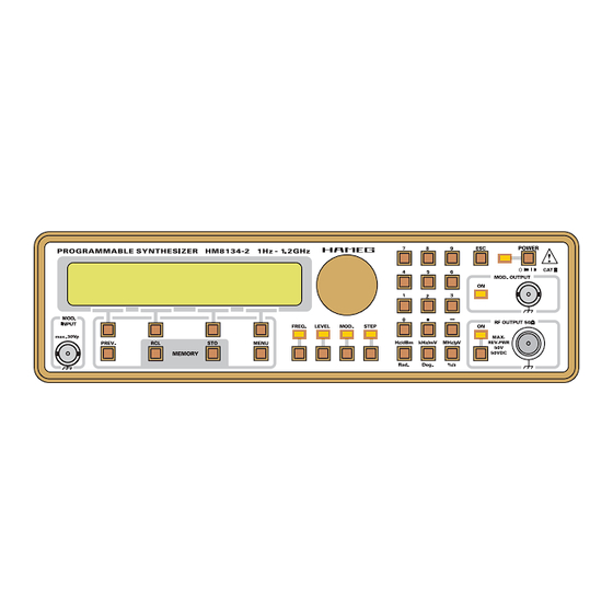
Page 8: Control Elements Hm8134 (Front Side)
Control elements HM8134 Control elements HM8134 (Front side): (8) DISPLAY Two lines of 20 characters each on a backlight LCD. (1) POWER On / Off switch and led. (9) FUNCTIONS Functions keys and leds. (2) MOD. IN Input of external modulation. (10) DIGITAL ROTARY CONTROL (3) PREV. -
Page 9: Getting Started
Operation - Getting started Getting started «Escape» key (13) After depressing the power (red) key (1), the HM8134 display The «ESC» key allows the user to be back in the main display, will successively contain the following messages: unselecting the current function (9) or cancelling the numeric keypad input. -
Page 10: Selecting Modulations
Operation - Setting parameters A new value of this level can be entered from the data keypad (11) or modified by the digital rotary (10) or one of the four context sensitive keys (5). For more details, refer to the paragraph «... -
Page 11: Amplitude Modulation (Am)
Operation - Amplitude Modulation • DC coupled NUM (DC-100kHz). • AC coupled NUM (10Hz-100kHz). • Deviation (see corresponding paragraph). example 1: CH1→ modulation: first pulse width 150s. second pulse width 1.1ms. period 2.5ms (Fmod: 400Hz). CH2 → moduled signal (deviation: 2kHz). CH1 →... -
Page 12: Frequency Modulation (Fm)
Operation - Frequence Modulation example 7: For AM negative ramp (depth: 50%), we get: example 4: For AM square (depth: 50%), we get: Frequence modulation (FM) From the FM menu, after selecting of the context sensitive key «Dev» (5), we get: A new value of this deviation can be entered from the data keypad (11) or modified by the digital rotary (10) or one of the example 5:... -
Page 13: Phase Modulation (Pm)
Operation - Phase Modulation - Gate Modulation CH1 → modulation. CH1 → modulation. CH2 → modulated signal (deviation: 1rad). CH2 → modulated signal (deviation: 80kHz). It is a way to get a FSK modulation. It is a way to get a PSK modulation. Phase modulation (PM) GATE modulation From the PM menu, after selecting of the context sensitive... -
Page 14: Selecting Step
Operation - Menu key Reference «Ref» The HM8134 is basically equipped with a temperature compensated crystal oscillator 10MHz. The option (OCXO) with a high-stability 5 10-8 (10 to 40°C) is available. At every access to the config menu and after selecting a context sensitive keys «Ref»... -
Page 15: Serial Interface (Standard Ho90)
Operation - Interface - Remote operation Serial interface (standard HO90) The current configuration can be stored by pressing a numeric key from 0 to 9. After pressing the «RCL» key (4), we get: It is possible to select the transmission rates 300, 600, 1200, 2400, 4800 or 9600 Bauds by pressing the context sensitive key (5). -
Page 16: Commands Supported
Operation - Commands description Commands supported Sound commands General Beep off soft Beep There are two kinds of commands. The first one is the set of loud Beep old commands which are HM8133-2 compatible. They are Commands tree - OUTPUT normally understood by the instrument without changing existing programs. -
Page 17: Commands Tree - Phase
Operation - Commands tree Syntax: :PULM:POLarity NORMal | INVert :PULM:POLarity? :FREQuency[:CW|:FIXed] <NUM> :FREQuency[:CW|:FIXed]? The line (3) allows you to set the validation level of the GATE modulation, the NORMal parameter is for a high level validation, The line (1) allows you to modify the carrier frequency, the and INVert is for a low level validation. -
Page 18: Commands Tree - Fm (Frequency Modulation)
Operation - Commands tree The line (9) allows you to turn the AM modulation on or off. The off (if present). The line (10) asks the current FM state to the parameters «1» or «ON» turn the AM on, and «0» or «OFF» instrument. -
Page 19: Commands Tree - System
Operation - Commands tree «PM:STAT 1» command (the operation is the same as the (it also set it to zero at power on time). Refer to the table of the keypad). error codes hereafter. General syntax note :PM:INTern:FREQuency <NUM> :PM:INTern:FREQuency? As mentionned in some examples above, in each command The line (7) allows you to change the frequency of the internal line the first character «:»... -
Page 20: Error Codes And Their Meaning
Operation - Error codes and their meaning Error codes and their meaning No error Direct Digital Synthesis error (Hardware) Internal reference error (Hardware) External reference error (Hardware) PLL1 error (Hardware) PLL2 error (Hardware) Calibration error Overload error (Hardware) Level error (out of range) (Carrier) frequency error (out of range) AM modulation in progress (impossible to turn another modulation on) PM modulation in progress (impossible to turn another modulation on) -
Page 21: Flowchart Menu
Flowchart Menu Function selection Subject to change without notice... - Page 22 Flowchart Menu Step Control Subject to change without notice...
- Page 23 Flowchart Menu Amplitude Modulation Control Subject to change without notice...
- Page 24 Flowchart Menu Phase Modulation Control Subject to change without notice...
- Page 25 Flowchart Menu Frequency Modulation Control Subject to change without notice...
- Page 26 Flowchart Menu Gate Control Subject to change without notice...
- Page 27 Flowchart Menu Main Menu Control Subject to change without notice...
-
Page 28: Synoptic
Synoptic Referency loop CREF Principal loop PLL1-134 Subject to change without notice... -
Page 29: Secondary Loop Pll2-134
Synoptic Secondary loop PLL2-134 Transposition TRA-134 Subject to change without notice... -
Page 30: Frequency Synthesize Dds134
Synoptic Frequency synthesize DDS134 Level lock loop AMPL134 Subject to change without notice... -
Page 31: Programmable Attenuator Atp134
Synoptic Programmable attenuator ATP134 Subject to change without notice... -
Page 32: Conversion
Conversion ρ ↔ V. S.W.R. REFLECTED FACTOR STATIONARY WAVE RATIO ρ − ρ = VSWR = ρ − VSWR VSWR VSWR VSWR |ρ| |ρ| |ρ| |ρ| 0.00 1.00 0.25 1.67 0.50 3.00 0.75 7.00 0.01 1.02 0.26 1.70 0.51 3.08 0.76 7.33 0.02... - Page 33 Conversion dBm ↔ Volt CONVERSION dBm → Volt CONVERSION Volt → dBm ⋅ ⋅ ⋅ ⋅ Ω with: Volt Volt Volt Volt Volt +20.0 2.236 +16.0 1.411 +12.0 0.890 +8.0 0.562 +4.0 0.354 +19.9 2.210 +15.9 1.395 +11.9 0.880 +7.9 0.555 +3.9 0.350...
- Page 34 Conversion dBm ↔ mW CONVERSION mW → dBm CONVERSION dBm → mW ⋅ ⋅ with: P +20.0 100.000 +16.0 39.811 +12.0 15.849 +8.0 6.310 +4.0 2.512 +19.9 97.724 +15.9 38.905 +11.9 15.488 +7.9 6.166 +3.9 2.455 +19.8 95.499 +15.8 38.019 +11.8 15.136 +7.8...
- Page 35 Conversion dBm ↔ Ratio CONVERSION Ratio → dBm CONVERSION dBm → Ratio ⋅ = 10 20 log Ratio Ratio Ratio Ratio Ratio 1.000 1.698 2.884 13.8 4.898 18.4 8.318 1.012 1.718 2.917 13.9 4.955 18.5 8.414 1.023 1.738 2.951 14.0 5.012 18.6 8.511...
- Page 36 Conversion dBµV ↔ Volt CONVERSION Volt → dBµV CONVERSION dBµV → Volt µ dB V ⋅ ⋅ µ dB V = µV with: U dBµV µVolt dBµV µVolt dBµV mVolt dBµV mVolt dBµV Volt 1.00 1.00 1.00 1.12 1.12 1.12 1.26 1.26 1.26...
- Page 37 Subject to change without notice...
- Page 38 Subject to change without notice...
- Page 39 LEER...
- Page 40 Oscilloscopes Multimeters Counters Frequency Synthesizers Generators R- and LC-Meters Spectrum Analyzers Power Supplies Curve Tracers HAMEG GmbH Industriestraße 6 D-63533 Mainhausen Telefon: +49 (0) 6182 / 800-0 Telefax: +49 (0) 6182 / 800-100 E-mail: sales@hameg.de service@hameg.de Internet: www.hameg.de Printed in Germany...
Need help?
Do you have a question about the HM8134-2 and is the answer not in the manual?
Questions and answers