Table of Contents
Advertisement
Advertisement
Table of Contents

Related Manuals for Asus P5N7A-VM


Summary of Contents for Asus P5N7A-VM
- Page 1 P5N7A-VM...
- Page 2 Product warranty or service will not be extended if: (1) the product is repaired, modified or altered, unless such repair, modification of alteration is authorized in writing by ASUS; or (2) the serial number of the product is defaced or missing.
-
Page 3: Table Of Contents
Contents Notices ... vi Safety information ... vii About this guide ... viii P5N7A-VM specifications summary ... x Chapter 1: Product introduction Welcome! ... 1-2 Package contents ... 1-2 Special features ... 1-2 1.3.1 Product highlights ... 1-2 1.3.2 ASUS Special Features ... 1-5 1.3.3... - Page 4 2.1.1 ASUS Update utility ... 2-2 2.1.2 Creating a bootable floppy disk ... 2-5 2.1.3 ASUS EZ Flash 2 utility ... 2-6 2.1.4 AFUDOS utility ... 2-7 2.1.5 ASUS CrashFree BIOS 3 utility ... 2-9 BIOS setup program ... 2-11 2.2.1...
- Page 5 Boot Device Priority ... 2-33 2.6.2 Boot Settings Configuration ... 2-34 2.6.3 Security ... 2-35 Tools menu ... 2-37 2.7.1 ASUS EZ Flash 2 ... 2-37 2.7.2 Express Gate ... 2-38 2.7.3 AI NET 2... 2-38 Exit menu ... 2-39 Chapter 3: Software support Installing an operating system ...
-
Page 6: Federal Communications Commission Statement
Notices Federal Communications Commission Statement This device complies with Part 15 of the FCC Rules. Operation is subject to the following two conditions: • This device may not cause harmful interference, and • This device must accept any interference received including interference that may cause undesired operation. -
Page 7: Electrical Safety
Safety information Electrical safety • To prevent electrical shock hazard, disconnect the power cable from the electrical outlet before relocating the system. • When adding or removing devices to or from the system, ensure that the power cables for the devices are unplugged before the signal cables are connected. If possible, disconnect all power cables from the existing system before you add a device. -
Page 8: Where To Find More Information
Refer to the following sources for additional information and for product and software updates. ASUS websites The ASUS website provides updated information on ASUS hardware and software products. Refer to the ASUS contact information. Optional documentation Your product package may include optional documentation, such as warranty flyers, that may have been added by your dealer. -
Page 9: Conventions Used In This Guide
Conventions used in this guide To ensure that you perform certain tasks properly, take note of the following symbols used throughout this manual. DANGER/WARNING: Information to prevent injury to yourself when trying to complete a task. CAUTION: Information to prevent damage to the components when trying to complete a task. -
Page 10: P5N7A-Vm Specifications Summary
32-bit operation system may only recognize less ® than 3GB. Hence, a total installed memory of less than 3GB is recommended. • Refer to www.asus.com or this user manual for the Memory QVL (Qualified Vendors Lists). Intergrated NVIDIA GeForce Series DirectX10 Shader ®... - Page 11 Stepless Frequency Selection (SFS): - SB tuning from 133 to 600MHz at 1MHz increment Overclocking Protection: - ASUS CPU Parameter Recall (C.P.R.) 3 x USB connectors support 6 additional USB ports 1 x Floppy disk drive connector 1 x IDE connector...
- Page 12 P5N7A-VM specifications summary Rear panel connectors BIOS features Manageability Accessories Support DVD contents Form factor *Specifications are subject to change without notice. 1 x PS/2 keyboard/mouse combo port 1 x VGA port 1 x Optical S/PDIF Out port 1 x DisplayPort...
-
Page 13: Chapter 1: Product Introduction
This chapter describes the motherboard features and the new technologies it supports. Chapter 1: Product introduction... -
Page 14: Welcome
Green ASUS This motherboard and its packaging comply with the European Union’s Restriction on the use of Hazardous Substances (RoHS). This is in line with the ASUS vision of creating environment-friendly and recyclable products/packaging to safeguard consumers’ health while minimizing the impact on the environment. - Page 15 Gigabit LAN solution Gigabit LAN is the networking standard for the early future and is ideal for handling large amounts of data such as video, audio, and voice. See page 1-28 for details. ASUS P5N7A-VM HD processor, SLI ® ) Technology, the world’s...
-
Page 16: High Definition Audio
PCI Express 2.0 support The motherboard supports the latest PCI Express 2.0 devices for double speed and bandwidth which enhances system performance.See page 1-26 for details. Serial ATA 3Gb/s technology The motherboard supports SATA hard drives based on the new SATA 3Gb/s storage specification. -
Page 17: Dvi Interface
To wake the system and return to the OS environment, simply click the mouse or press a key. Q-Fan 2 ASUS Q-Fan 2 technology intelligently adjusts both CPU fan and chassis fan speeds according to system loading to ensure quiet, cool and efficient operation. ASUS P5N7A-VM... - Page 18 ASUS EZ DIY ASUS EZ DIY feature collection provides you easy ways to install computer components, update the BIOS or back up your favorite settings. ASUS Q-Connector ASUS Q-Connector allows you to easily connect or disconnect the chassis front panel cables to the motherboard. This unique module eliminates the trouble of connecting the system panel cables one at a time and avoiding wrong cable connections.
-
Page 19: Asus Stylish Features
• The actual boot time depends on the system configuration, hardware configuration, and product model. • ASUS Express Gate supports file uploading from SATA HDDs, ODDs and USB drive and downloading to USB drives only. 1.3.4 ASUS Intelligent Overclocking features C.P.R. -
Page 20: Before You Proceed
ON, in sleep mode, or in soft-off mode. This is a reminder that you should shut down the system and unplug the power cable before removing or plugging in any motherboard component. The illustration below shows the location of the onboard LED. P5N7A-VM P5N7A-VM Onboard LED SB_PWR Standby Powered Power... -
Page 21: Motherboard Overview
Place six (6) screws into the holes indicated by circles to secure the motherboard to the chassis. Do not overtighten the screws! Doing so can damage the motherboard. Place this side towards the rear of the chassis ASUS P5N7A-VM P5N7A-VM... -
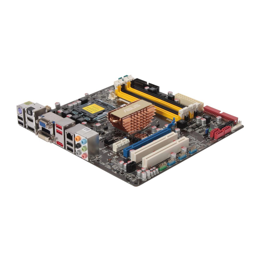
Page 22: Motherboard Layout
8211CL ALC1200 SPDIF_OUT AAFP Refer to 1.10 Connectors for more information about rear panel connectors and internal connectors. 1-10 23.4cm (9.2in) LGA775 MCP7A-S CLRTC P5N7A-VM CR2032 3V Lithium Cell CMOS Power PCIEX16 PCI1 PCI2 USB78 USB910 USB1112 COM1 Super I/O... -
Page 23: Central Processing Unit (Cpu)
ASUS will shoulder the cost of repair only if the damage is shipment/transit-related. • Keep the cap after installing the motherboard. ASUS will process Return Merchandise Authorization (RMA) requests only if the motherboard comes with the cap on the LGA775 socket. - Page 24 Press the load lever with your thumb (A) and move it to the left (B) until it is released from the retention tab. Retention tab Load lever To prevent damage to the socket pins, do not remove the PnP cap unless you are installing a CPU.
- Page 25 The CPU fits in only one correct orientation. DO NOT force the CPU into the socket to prevent bending the connectors on the socket and damaging the CPU! The motherboard supports Intel SpeedStep Technology (EIST), and Hyper-Threading Technology. ® ASUS P5N7A-VM Alignment key Gold triangle mark LGA775 processors with the Enhanced Intel ® 1-13...
-
Page 26: Installling The Cpu Heatsink And Fan
1.6.2 Installling the CPU heatsink and fan Intel Core™ 2 Quad/Core™ 2 Duo/Pentium D/Pentium ® require a specially designed heatsink and fan assembly to ensure optimum thermal condition and performance. • Install the motherboard to the chassis before you install the CPU fan and heatsink assembly •... - Page 27 When the fan and heatsink assembly is in place, connect the CPU fan cable to the connector on the motherboard labeled CPU_FAN. P5N7A-VM P5N7A-VM CPU Fan Connector • Do not forget to connect the CPU fan connector! Hardware monitoring errors can occur if you fail to plug this connector.
-
Page 28: Uninstalling The Cpu Heatsink And Fan
1.6.3 Uninstalling the CPU heatsink and fan To uninstall the CPU heatsink and fan: Disconnect the CPU fan cable from the connector on the motherboard. Rotate each fastener counterclockwise. Pull up two fasteners at a time in a diagonal sequence to disengage the heatsink and fan assembly from the motherboard. - Page 29 (The photo shows the groove shaded for emphasis.) Refer to the documentation in the boxed or stand-alone CPU fan package for detailed information on CPU fan installation. ASUS P5N7A-VM Narrow end of the groove 1-17...
-
Page 30: Memory Configurations
Overview The motherboard comes with four Double Data Rate 2 (DDR2) Dual Inline Memory Modules (DIMM) sockets. The figure illustrates the location of the DDR2 DIMM sockets: P5N7A-VM P5N7A-VM 240-pin DDR2 DIMM Sockets Channel Channel A Channel B 1.7.2 Memory configurations You may install 256 MB, 512 MB, 1 GB, 2 GB, and 4 GB unbuffered non-ECC DDR2 DIMMs into the DIMM sockets. - Page 31 Due to chipset limitation, DDR2-800 with CL=4 will be downgraded to run at DDR2-667 by default setting. If you want to operate with lower latency, adjust the memory timing manually. P5N7A-VM Motherboard Qualified Vendors Lists (QVL) DDR2-667MHz capability Size Vendor Part No.
- Page 32 DDR2-667MHz capability Size Vendor Part No. 512MB Kingmax KLCC28F-A8KB5 Kingmax KLCD48F-A8KB5 512MB Apacer AU512E667C5KBGC 512MB Apacer 78.91G92.9K5 Apacer 78.01G9O.9K5 Apacer AU01GE667C5KBGC Apacer AU01GE667C5KBGC Transcend 506010-4894 512MB ADATA M2OAD5G3H3160Q1C52 ADATA M2OAD5G314170Q1C58 ADATA M2OAD5H3J4170I1C53 512MB AL6E8E63J-6E1 AL7E8E63J-6E1 AL7E8F73C-6E1 512MB Nanya NT512T64U88A1BY-3C Nanya NT1GT64U8HB0BY-3C GEIL GX21GB5300SX...
- Page 33 TS128MLQ64V8J 512MB ADATA M2OAD6G3H3160Q1E58 512MB VDATA M2GVD6G3H3160Q1E52 ADATA M2OAD6G314170Q1E58 AL8E8F73C-8E1 PL8E8F73C-8E1 PL8E8G73E-8E1 GEIL GB24GB6400C4QC GEIL GB22GB6400C5DC GEIL GB24GB6400C5QC ASUS P5N7A-VM Chip Brand Chip No. Kingston Heat-Sink Package Elpida E2108ABSE-8G-E Kingston E5108AJBG-8E-E 0803A9082 Samsung K4T51083QG-HCF7 Samsung K4T1G084QQ-HCF7 Samsung K4T51083QG-HCF7 Samsung K4T1G084QQ-HCF7...
- Page 34 Dual-channel memory configuration. • C*: Supports four modules inserted into both the yellow and black slots as two pairs of Dual-channel memory configuration. Visit the ASUS website for the latest DDR2-667/800 MHz QVL. 1-22 Chip Brand Chip No.
-
Page 35: Installing A Dimm
Support the DIMM lightly with your fingers when pressing the retaining clips. The DIMM might get damaged when it flips out with extra force. Remove the DIMM from the socket. ASUS P5N7A-VM DDR2 DIMM notch Unlocked retaining clip DDR2 DIMM notch 1-23... -
Page 36: Expansion Slots
Expansion slots In the future, you may need to install expansion cards. The following sub-sections describe the slots and the expansion cards that they support. Ensure to unplug the power cord before adding or removing expansion cards. Failure to do so may cause you physical injury and damage motherboard components. -
Page 37: Interrupt Assignments
Internal devices interrupt Onboard USB controller Onboard USB 2.0 controller Onboard USB controller 1 Onboard USB 2.0 controller 1 Onboard LAN Onboard SATA controller Onboard HD Audido Onboard VGA ASUS P5N7A-VM PIRQ1 PIRQ2 PIRQ3 PIRQ4 shared shared shared shared shared... -
Page 38: Pci Slots
1.8.4 PCI slots The PCI slots support cards such as a LAN card, SCSI card, USB card, and other cards that comply with PCI specifications. The figure shows a LAN card installed on a PCI slot. 1.8.5 PCI Express x1 slot This motherboard supports PCI Express x1 network cards, SCSI cards and other cards that comply with the PCI Express... -
Page 39: Clear Rtc Ram
Removing the cap will cause system boot failure! P5N7A-VM P5N7A-VM Clear RTC RAM You do not need to clear the RTC when the system hangs due to overclocking. For system failure due to overclocking, use the C.P.R. (CPU Parameter Recall) feature. -
Page 40: 1.10 Connectors
1.10 Connectors 1.10.1 Rear panel connectors PS/2 keyboard/mouse combo port (purple). This port is for a PS/2 keyboard/mouse. Optical S/PDIF Out port. This port connects an external audio output device via an optical S/PDIF cable. Video Graphics Adapter (VGA) port. This 15-pin port is for a VGA monitor or other VGA-compatible devices. - Page 41 Due to the chipset limitation, simultaneous output for DVI and HDMI is not supported. • To play HD DVD or Blu-Ray Disc, ensure to use an HDCP compliant monitor. ASUS P5N7A-VM 4-channel 6-channel Line In Line In Front Speaker Out...
-
Page 42: Internal Connectors
• Pin 5 on the connector is removed to prevent incorrect cable connection when using an FDD cable with a covered Pin 5. • The floppy disk drive cable is purchased separately. P5N7A-VM Floppy Disk Drive Connector P5N7A-VM 1-30 FLOPPY... - Page 43 Digital audio connector (4-1 pin SPDIF_OUT for ASUS HDMI VGA card) This connector is for an additional Sony/Philips Digital Interface (S/PDIF) port(s). If you are using an ASUS HDMI-equipped graphics card, connect the HDMI card to this connector with a S/PDIF Out cable.
-
Page 44: Ide Connector
IDE cable. • Use the 80-conductor IDE cable for Ultra DMA 133/100 IDE devices. If any device jumper is set as “Cable-Select,” ensure all other device jumpers have the same setting. P5N7A-VM IDE Connector P5N7A-VM 1-32 Drive jumper setting... - Page 45 [red], SATA4 [red], SATA5 [black], SATA6 [black]) These connectors are for the Serial ATA signal cables for Serial ATA hard disk drives. P5N7A-VM P5N7A-VM SATA Connectors • Connect the right-angle side of SATA signal cable to SATA device. Or you may...
- Page 46 Never connect a 1394 cable to the USB connectors. Doing so will damage the motherboard! You can connect the front panel USB cable to the ASUS Q-Connector (USB, blue) first, and then install the Q-Connector (USB) to the USB connector onboard if your chassis supports front panel USB ports.
- Page 47 These are not jumpers! Do not place jumper caps on the fan connectors! P5N7A-VM P5N7A-VM CPU Fan Connector The CPU fan and the chassis fan connectors support the ASUS Q-FAN 2 feature. ASUS P5N7A-VM (black)
- Page 48 HD Audio or legacy AC`97 audio standard. Connect one end of the front panel audio I/O module cable to this connector. P5N7A-VM P5N7A-VM Azalia Analog Front Panel Connector • We recommend that you connect a high-definition front panel audio module to this connector to avail of the motherboard’s high-definition audio capability.
- Page 49 Find the proper orientation and push down firmly until the connectors completely fit. P5N7A-VM P5N7A-VM ATX Power Connector • For a fully configured system, we recommend that you use a power supply unit (PSU) that complies with ATX 12 V Specification 2.0 (or later version)
-
Page 50: System Panel Connector
13. System panel connector (20-8 pin PANEL) This connector supports several chassis-mounted functions. P5N7A-VM P5N7A-VM System Panel Connector • System power LED (2-pin PLED) This 2-pin connector is for the system power LED. Connect the chassis power LED cable to this connector. The system power LED lights up when you turn on the system power, and blinks when the system is in sleep mode. -
Page 51: Asus Q-Connector (System Panel)
ASUS Q-Connector (system panel) You can use the ASUS Q-Connector to connect/disconnect chassis front panel cables in a few steps. Refer to the instructions below to install the ASUS Q-Connector. Connect the front panel cables to the ASUS Q-Connector. Refer to the labels on the Q-Connector... - Page 52 1-40 Chapter 1: Product Introduction...
-
Page 53: Chapter 2: Bios Setup
This chapter tells how to change the system settings through the BIOS Setup menus. Detailed descriptions of the BIOS parameters are also provided. Chapter 2: BIOS setup... -
Page 54: Managing And Updating Your Bios
Input/Output System (BIOS) setup. ASUS Update: Updates the BIOS in Windows ASUS EZ Flash 2: Updates the BIOS using a floppy disk or USB flash disk. ASUS AFUDOS: Updates the BIOS using a bootable floppy disk. ASUS CrashFree BIOS 3: Updates the BIOS using a bootable floppy disk, USB flash disk or the motherboard support DVD when the BIOS file fails or gets corrupted. - Page 55 Updating the BIOS through the Internet To update the BIOS through the Internet: Launch the ASUS Update utility from the Windows > Programs > ASUS > ASUSUpdate > ASUSUpdate. The ASUS Update main window appears. Select Update BIOS from the Internet option from the drop-down menu, then click Next.
- Page 56 Updating the BIOS through a BIOS file To update the BIOS through a BIOS file: Launch the ASUS Update utility from the Windows > Programs > ASUS > ASUSUpdate > ASUSUpdate. The ASUS Update main window appears. Select Update BIOS from a file option from the drop-down menu, then click Next.
-
Page 57: Creating A Bootable Floppy Disk
Select the Create an MS-DOS startup disk check box. e. Click Start. Copy the original or the latest motherboard BIOS file to the bootable floppy disk. ASUS P5N7A-VM desktop, then select My Computer. ® desktop, then select Computer. ®... -
Page 58: Asus Ez Flash 2 Utility
2.1.3 ASUS EZ Flash 2 utility The ASUS EZ Flash 2 feature allows you to update the BIOS without having to go through the long process of booting from a floppy disk and using a DOS-based utility. The EZ Flash 2 utility is built-in the BIOS chip so it is accessible by pressing <Alt>... -
Page 59: Afudos Utility
The utility returns to the DOS prompt after copying the current BIOS file. Updating the BIOS file To update the BIOS file using the AFUDOS utility: Visit the ASUS website (www.asus.com) and download the latest BIOS file for the motherboard. Save the BIOS file to a bootable floppy disk. ASUS P5N7A-VM... - Page 60 A:\>afudos /iP5N7AVM.ROM The utility verifies the file and starts updating the BIOS. A:\>afudos /iP5N7AVM.ROM AMI Firmware Update Utility - Version 1.19(ASUS V2.07(03.11.24BB)) Copyright (C) 2002 American Megatrends, Inc. All rights reserved. WARNING!! Do not turn off power during flash BIOS Reading file ...
-
Page 61: Asus Crashfree Bios 3 Utility
2.1.5 ASUS CrashFree BIOS 3 utility The ASUS CrashFree BIOS 3 is an auto recovery tool that allows you to restore the BIOS file when it fails or gets corrupted during the updating process. You can update a corrupted BIOS file using the motherboard support DVD, the floppy disk or the USB flash disk that contains the updated BIOS file. - Page 62 Restart the system after the utility completes the updating process. • Only the USB flash disk with FAT 32/16 format and single partition can support ASUS CrashFree BIOS 3. The device size should be smaller than 8GB. • DO NOT shut down or reset the system while updating the BIOS! Doing so...
-
Page 63: Bios Setup Program
The BIOS setup screens shown in this section are for reference purposes only, and may not exactly match what you see on your screen. • Visit the ASUS website (www.asus.com) to download the latest BIOS file for this motherboard. ASUS P5N7A-VM... -
Page 64: Bios Menu Screen
2.2.1 BIOS menu screen Menu items Menu bar Main Advanced System Time System Date Legacy Diskette A SATA 1 SATA 2 ESATA SATA 4 Storage Coniguration System Information v02.61 (C)Copyright 1985-2008, American Megatrends, Inc. Sub-menu items 2.2.2 Menu bar The menu bar on top of the screen has the following main items: Main For changing the basic system configuration Advanced... -
Page 65: Menu Items
Down> keys to display the other items on the screen. 2.2.9 General help At the top right corner of the menu screen is a brief description of the selected item. ASUS P5N7A-VM System Time [06:22:54] System Date [Fri 03/09/2007] Legacy Diskette A [1.44M, 3.5 in]... -
Page 66: Main Menu
Main menu When you enter the BIOS Setup program, the Main menu screen appears, giving you an overview of the basic system information. Refer to section 2.2.1 BIOS menu screen for information on the menu screen items and how to navigate through them. Main Advanced System Time... -
Page 67: Sata 1/2/4; Esata
Configuration options: [Disabled] [Auto] PIO Mode [Auto] Selects the PIO mode. Configuration options: [Auto] [0] [1] [2] [3] [4] DMA Mode [Auto] Selects the DMA mode. Configuration options: [Auto] ASUS P5N7A-VM BIOS SETUP UTILITY [Auto] [Auto] [Auto] [Auto]... -
Page 68: Storage Configuration
SMART Monitoring [Auto] Enables or disables the S.M.A.R.T. (Self-Monitoring Analysis and Reporting Technology) capability of your hard drive. This features allows your system to report read/write errors of the hard drive and to issue warnings when a third party hardware monitor utility is installed. Configuration options: [Auto] [Disabled] [Enabled] 32Bit Data Transfer [Enabled] Enables or disables 32-bit data transfer. -
Page 69: System Information
(C)Copyright 1985-2008, American Megatrends, Inc. AMI BIOS Displays the auto-detected BIOS information. Processor Displays the auto-detected CPU specification. System Memory Displays the auto-detected system memory. ASUS P5N7A-VM BIOS SETUP UTILITY Select Screen Select Item General Help Save and Exit Exit... -
Page 70: Advanced Menu
Advanced menu The Advanced menu items allow you to change the settings for the CPU and other system devices. Take caution when changing the settings of the Advanced menu items. Incorrect field values can cause the system to malfunction. Main Advanced CPU Configuration JumperFree Configuration... -
Page 71: Cpu Configuration
Virtualization Technology allows a platform to run multiple ® operating systems and applications in independent partitons. With virtualization, one computer system can function as multiple virtual systems. Configuration options: [Enabled] [Disabled] ASUS P5N7A-VM BIOS SETUP UTILITY Sets the ratio between CPU Core Clock and the FSB Frequency. -
Page 72: Jumperfree Configuration
CPU TM Function [Enabled] Enables or disables Intel protection function. When enabled, the CPU core frequency and voltage are reduced when the CPU overheats. Configuration options: [Disabled] [Enabled] Execute-Disable Bit Capability [Enabled] Allows you to enable or disable Intel enhance protection of your computer, reducing exposure to viruses and malicious buffer overflow attacks when working with its supporting software and system. - Page 73 Allows you to enter an integer value from 450MHz to 999MHz to overclock for GPU. Configuration options: [Min.=450] [Max.=999] Shader OverClock [1200] Allows you to enter an integer value from 1200MHz to 2000MHz to overclock for shader. Configuration options: [Min.=1200] [Max.=2000] ASUS P5N7A-VM 2-21...
-
Page 74: Cpu Voltage [Auto]
Memory Over Voltage [Auto] Allows you to set the Memory Over Voltage. Use +/- to adjust the voltage. The increment is 0.00625V. The standard value is 1.85000V. Configuration options: [Auto] [Min = 1.850000V] [Max = 2.24375V] Chipset Over Voltage [Auto] Allows you to set the Chipset Over Voltage. -
Page 75: Chipset
Configuration options: [Disabled] [Enabled] Primary Graphics Adapter [PCIE VGA Card First] Display Device Priority, from high to low. Configuration options: [PCI VGA Card First] [Internal VGA First] [PCIE VGA Card First] ASUS P5N7A-VM BIOS SETUP UTILITY Options for NorthBridg [Disabled]... - Page 76 iGPU and Ext-VGA Selection [Disable iGPU if Ex] Allows you to select the internal VGA card or the external VGA card to display. Configuration options: [Disable iGPU if External VGA Card Exist] [Both Exist and iGPU by Frame Buffer Detect] iGPU Frame Buffer Detect [Auto] Allows you to disable the iGPU Frame Buffer Detect or set it to auto mode.
-
Page 77: Onboard Devices Configuration
Allows you to select the parallel port EPP version.Configuration options: [1.9] [1.7] Parallel Port IRQ [IRQ7] Allows you to select the parellet port IRQ.Configuration options: [IRQ5] [IRQ7] ASUS P5N7A-VM BIOS SETUP UTILITY Allows BIOS to Select Serial Port1 Base Addreses. - Page 78 AZALIA Audio [Auto] Allows you to enable or disable the AZALIA Audio. Configuration options: [Disabled] [Auto] Front Panel Type [HD Audio] Allows you to set the front panel audio connector (AAFP) mode to legacy AC’97 or high-definition audio depending on the audio standard that the front panel audio module supports.
-
Page 79: Usb Configuration
Allows you to set the USB 2.0 controller mode to HiSpeed (480 Mbps) or FullSpeed (12 Mbps). This item appears only when you enable the USB 2.0 Controller item. Configuration options: [FullSpeed ] [HiSpeed ] ASUS P5N7A-VM BIOS SETUP UTILITY Disabled... -
Page 80: Pcipnp
2.4.6 PCIPnP The PCI PnP menu items allow you to change the advanced settings for PCI/PnP devices. Take caution when changing the settings of the PCI PnP menu items. Incorrect field values can cause the system to malfunction. Advanced Advanced PCI/PnP Settings WARNING: Setting wrong values in below sections may cause system to malfunction. -
Page 81: Power Menu
Allows you to enable or disable the Advanced Configuration and Power Interface (ACPI) support in the Application-Specific Integrated Circuit (ASIC). When set to Enabled, the ACPI APIC table pointer is included in the RSDT pointer list. Configuration options: [Disabled] [Enabled] ASUS P5N7A-VM BIOS SETUP UTILITY Boot Tools... -
Page 82: Apm Configuration
2.5.4 APM Configuration Restore on AC Power Loss APM Resume Event Configuration Power On PCI Wake Power On PCIE Wake# Power On LAN(MAC) Power On Ring Power On PS/2 Keyboard Power On RTC Alarm v02.61 (C)Copyright 1985-2008, American Megatrends, Inc. Restore On AC Power Loss [Power Off] When set to Power Off, the system goes into off state after an AC power loss. -
Page 83: Hardware Monitor
(RPM). If the fan is not connected to the motherboard, the field shows N/A. CPU Q-Fan Control [Enabled] Allows you to enable or disable the CPU Q-Fan controller. Configuration options: [Disabled] [Enabled] ASUS P5N7A-VM BIOS SETUP UTILITY CPU Temperature [30ºC/86ºF] [36ºC/96.5ºF]... -
Page 84: Chassis Q-Fan Control [Enabled]
The CPU Fan Profile item appears when you enable the CPU Q-Fan Control feature. CPU Fan Profile [Optimal] Allows you to set the appropriate performance level of the CPU Q-Fan. When set to [Optimal], the CPU fan automatically adjusts depending on the CPU temperature. -
Page 85: Boot Menu
These items specify the boot device priority sequence from the available devices. The number of device items that appears on the screen depends on the number of devices installed in the system. Configuration options: [1st FLOPPY DRIVE] [Hard Drive] [ATAPI CD_ROM] [Disabled] ASUS P5N7A-VM BIOS SETUP UTILITY Boot Tools... -
Page 86: Boot Settings Configuration
Allows you to enable or disable the full screen logo display feature. Configuration options: [Disabled] [Enabled] Set this item to [Enabled] to use the ASUS MyLogo 2™ feature. AddOn ROM Display Mode [Force BIOS] Sets the display mode for option ROM. Configuration options: [Force BIOS] [Keep... -
Page 87: Security
Real Time Clock (RTC) RAM. See section “1.9 Jumper” for information on how to erase the RTC RAM. After you have set a supervisor password, the other items appear to allow you to change other security settings. ASUS P5N7A-VM BIOS SETUP UTILITY Boot :Not Installed :Not Installed <Enter>... -
Page 88: Change User Password
Security Settings Supervisor Password User Password Change Supervisor Password User Access Level Change User Password Clear User Password Password Check User Access Level [Full Access] This item allows you to select the access restriction to the Setup items. Configuration options: [No Access] [View Only] [Limited] [Full Access] No Access prevents user access to the Setup utility. -
Page 89: Tools Menu
2.7.1 ASUS EZ Flash 2 Allows you to run ASUS EZ Flash 2. When you press <Enter>, a confirmation message appears. Use the left/right arrow key to select between [Yes] or [No], then press <Enter> to confirm your choice. Please see section 2.1.3 for details. -
Page 90: Express Gate
2.7.2 Express Gate [Enabled] Allows you to enable or disable the ASUS Express Gate feature. The ASUS Express Gate feature is a unique instant-on environment that provides quick access to the Internet browser and Skype. Configuration options: [Disabled] [Enabled] Enter OS Timer [10 Seconds] Allows you to set the countdown duration that the system waits at the Express Gate’s first screen before starting Windows or other installed OS. -
Page 91: Exit Menu
Setup menus. When you select this option or if you press <F5>, a confirmation window appears. Select OK to load default values. Select Exit & Save Changes or make other changes before saving the values to the non-volatile RAM. ASUS P5N7A-VM BIOS SETUP UTILITY Boot... - Page 92 2-40 Chapter 2: BIOS setup...
-
Page 93: Chapter 3: Software Support
This chapter describes the contents of the support DVD that comes with the motherboard package. Chapter 3: Software support... -
Page 94: Installing An Operating System
The contents of the support DVD are subject to change at any time without notice. Visit the ASUS website (www.asus.com) for updates. 3.2.1 Running the support DVD Place the support DVD to the optical drive. -
Page 95: Drivers Menu
The drivers menu shows the available device drivers if the system detects installed devices. Install the necessary drivers to activate the devices. ASUS InstAll - Installation Wizard for Anti-Virus and Drivers Utility Launches the ASUS installation wizard for anti-virus and drivers utility. -
Page 96: Utilities Menu
ASUS InstAll - Installation Wizard for Utilities Launches the ASUS InstallAll installation wizard for utilities. ASUS Update The ASUS Update utility allows you to update the motherboard BIOS in a Windows environment. This utility requires an Internet connection either through a ®... - Page 97 This smart utility monitors the fan speed, CPU temperature, and system voltages, and alerts you of any detected problems. This utility helps you keep your computer in healthy operating condition. ASUS AI Nap Installs the ASUS AI Nap application. ADOBE Acrobat Reader 8 Installs the Adobe Acrobat Reader that allows you to open, view, and print ®...
-
Page 98: Make Disk Menu
3.2.4 Make Disk menu The Make Disk menu allows you to make a RAID driver disk. NVIDIA 32/64bit XP AHCI Driver Allows you to create the NVIDIA 32/64-bit XP AHCI Driver disk for Windows Operating System (OS). NVIDIA 32/64bit Vista AHCI Driver Allows you to create the NVIDIA 32/64-bit Vista AHCI Driver disk for Windows Vista Operating System (OS). -
Page 99: Manual Menu
3.2.5 ASUS Contact information Click the Contact tab to display the ASUS contact information. You can also find this information on the inside front cover of this user guide. ASUS P5N7A-VM Reader from the Utilities menu before opening a user manual... -
Page 100: Other Information
3.2.6 Other information The icons on the top right corner of the screen give additional information on the motherboard and the contents of the support DVD. Click an icon to display the specified information. Motherboard Info Displays the general specifications of the motherboard. Browse this DVD Displays the support DVD contents in graphical format. -
Page 101: Technical Support Form
Technical support Form Displays the ASUS Technical Support Request Form that you have to fill out when requesting technical support. Filelist Displays the contents of the support DVD and a brief description of each in text format. ASUS P5N7A-VM... -
Page 102: Software Information
ASUS Express Gate ASUS Express Gate is an instant-on environment that gives you quick access to the Internet. Within a few seconds of powering on your computer, you will be at the Express Gate menu where you can start the web browser, Skype, or other Express Gate softwares. -
Page 103: The First Screen
The very first time you enter the Express Gate environment (by launching either web or Skype from the first screen), a first time wizard will guide you through basic Express Gate configurations. Basic configurations include language, date and time and screen resolution. ASUS P5N7A-VM 3-11... - Page 104 Once inside the Express Gate environment, click on the icons on the LaunchBar, by default at bottom of the screen, to launch or switch between softwares. You can re-arrange, re-size and move windows. Bring a window to the foreground by clicking within it or by clicking on its corresponding software icon. Re-size a window by dragging any of its four corners.
- Page 105 The first-time Wizard will run again when you enter the Express Gate environment after clearing its settings. Screen Settings: Choose the most optimal screen resolution for your display. • Volume Control: Control the volume for your speaker output, microphone • input, etc. ASUS P5N7A-VM 3-13...
- Page 106 USB drive. If a USB device is detected, the icon contains a green arrow. ASUS Express Gate supports file uploading from SATA HDDs, ODDs and USB drive and downloading to USB drives only. Shows network status; click to configure network.
- Page 107 Click to change LaunchBar options (auto-hide, docking position, etc). Click to show the “ASUS Utility” panel (if supported). Click to show “About Express Gate.” Click to open Express Gate Help. Click to bring up power options window to boot to OS, restart or power down.
- Page 108 Make the proper network configurations. Each network interface is enabled immediately when you check the box next to it. • If you use a network cable connected to a home router (which is then connected to your DSL/cable modem), enable LAN1. •...
- Page 109 Shows user- created image album(s) ASUS Express Gate supports HDDs connected to motherboard chipset- controlled onboard SATA ports only. All onboard extended SATA ports and external SATA ports are NOT supported. ASUS P5N7A-VM Search a game See games in...
- Page 110 Express Gate software will be released regularly, adding refinements or new applications. You can find original version of the software on the support DVD or download new versions from the ASUS support website. To update Express Gate Double-click the Express Gate setup file to start software update.
-
Page 111: Creating A Raid Driver Disk
Insert a floppy disk/USB device into the floppy disk drive/USB port. Follow the succeeding screen instructions to complete the process. Write-protect the floppy disk to avoid computer virus infection. ASUS P5N7A-VM ® 32/64 bit XP SATA RAID driver disk. ®... - Page 112 To install the RAID driver in Windows During the OS installation, the system prompts you to press the F6 key to install third-party SCSI or RAID driver. Press <F6> then insert the floppy disk with RAID driver into the floppy disk drive.
Need help?
Do you have a question about the P5N7A-VM and is the answer not in the manual?
Questions and answers