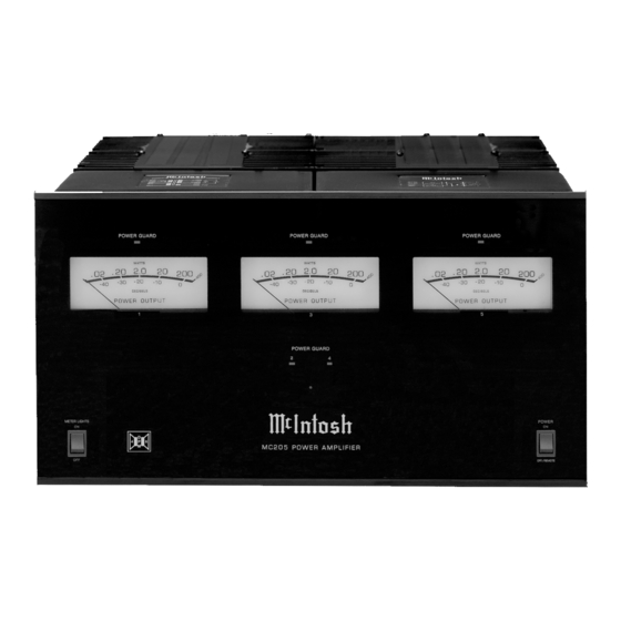
Summary of Contents for McIntosh MC205
-
Page 1: Power Amplifier
Power Amplifier MC205 Owner’s Manual McIntosh Laboratory, Inc. 2 Chambers Street Binghamton, New York 13903-2699 Phone: 607-723-3512 FAX: 607-724-0549... -
Page 2: Important Safety Instructions
The lightning flash with arrowhead, within an equilateral triangle, is intended to alert the user to the presence of uninsulated “danger- ous voltage” within the product’s enclosure that may be of sufficient magnitude to constitute a risk of electric shock to persons. WARNING - TO REDUCE RISK OF FIRE OR ELECTRICAL SHOCK, DO NOT EXPOSE THIS EQUIPMENT TO... -
Page 3: Table Of Contents
1. For additional connection information, refer to the owner’s manual(s) for any component(s) connected to the MC205 Power Amplifier. 2. The Main AC Power going to the MC205 and any other McIntosh Component(s) should not be applied until all the system components are connected together. Failure to do so could result in malfunctioning of some or all of the system’s normal operations. -
Page 4: Connector And Cable Information
• Sentry Monitor and Thermal Protection McIntosh Sentry Monitor power output stage protection Power Control circuits ensure the MC205 will have a long and trouble free Meter operating life. Built-in thermal protection circuits guard Illumination against overheating. -
Page 5: Dimensions
Dimensions The following dimensions can assist in determining the best location for your MC205. There is additional informa- tion on the next page pertaining to installing the MC205 into cabinets. Front View of the MC205 Rear View of the MC205 Side View of the MC205 "... -
Page 6: Installation
It also can be custom installed in a piece of furniture or cabinet of your choice. The four feet may be removed from the bottom of the MC205 when it is custom installed as outlined below. The four feet together... -
Page 7: Rear Panel Connections
Rear Panel Connections Connect the MC205 power cord to a live AC outlet. Refer to the rear panel to determine the correct voltage... -
Page 8: How To Connect For A Five Channel System
Left and Right Front Loudspeak- ers to set the IMPEDANCE Switch position. Figure 2 Figure 3 6. Connect the MC205 Power Cord to an active AC outlet. McIntosh A/V Control Center in the United States and Canada only. - Page 9 Left Front Loudspeaker To AC Outlet Left Surround Loudspeaker How to Connect for a Five Channel System Center Front Loudspeaker Right Front Loudspeaker Right Surround Loudspeaker...
-
Page 10: How To Connect For A Seven Channel System
Left and Right Front Loudspeak- ers to set the IMPEDANCE Switch position. 6. Connect the MC205 Power Cord to an active AC outlet. Figure 2 Figure 3 McIntosh A/V Control Center and present a risk of electric shock. - Page 11 McIntosh Two Channel Power Amplifier Right Front Loudspeaker Center Front Loudspeaker To AC Outlet Right Surround Loudspeaker Back Right Surround Loudspeaker How to Connect for a Seven Channel System Left Front Loudspeaker Left Surround Loudspeaker Back Left Surround Loudspeaker...
-
Page 12: How To Connect For A Five Channel And Zone B System
Left and Right Front Loudspeak- ers to set the IMPEDANCE Switch position. 6. Connect the MC205 Power Cord to an active AC outlet. McIntosh A/V Control Center Figure 2... -
Page 13: How To Connect For A Five Channel And Zone B System
McIntosh Two Channel Power Amplifier Right Front Loudspeaker Center Front Loudspeaker To AC Outlet Right Surround Loudspeaker Zone B Left Loudspeaker How to Connect for a Five Channel and Zone B System Left Surround Loudspeaker Zone B Right Loudspeaker Left Front... -
Page 14: Front Panel Displaysand Switches
LED indicates when Am- plifier Channels 1, 3 or 5 POWER GUARD circuit activates LED indicates when Amplifier Channels 2 or 4 POWER GUARD circuit activates METER LIGHTS Switch selects the Meter Illumination On or Off Front Panel Displays and Switches Standby Power On Indicator Meter indicates the Power... -
Page 15: How To Operate The Mc205
How to Operate the MC205 Power With the POWER Switch set to the OFF/REMOTE Posi- tion, the MC205 will turn On or Off when an A/V Control Center turns On or Off. For manual operation, place the POWER Switch to the ON Position as desired. Refer to figure... -
Page 16: Technical Description
McIntosh has ever manufactured. Refer to figures 13 and 14. The distortion limits for the MC205 are no more than 0.005% at rated power output for all frequencies from 20Hz to 20,000Hz. - Page 17 Power Supply Power Supply Circuits To compliment the design of the MC205, there is a high current power supply for the five power amplifier channels. Without Power Guard Refer to figure 18. The very large Power Transfomer, has toroidal windings on a toroidal core and can supply over 35 amps of continuous current.
-
Page 18: Specifications
120 Volts, 50/60Hz at 10 Amps 220 Volts, 50/60Hz at 6 Amps 230 Volts, 50/60Hz at 6 Amps 240 Volts, 50/60Hz at 6 Amps Note: Refer to the rear panel of the MC205 for the correct voltage. Overall Dimensions Width is 17-1/2 inches (44.45cm) Height is 9-7/16 inches (23.97cm) including feet... -
Page 19: Packing Instruction
If a shipping carton or any of the interior part(s) are needed, please call or write Customer Service Department of McIntosh Labo- ratory. Please see the Part List for the correct part numbers. - Page 20 McIntosh Laboratory, Inc. 2 Chambers Street Binghamton, NY 13903 The continuous improvement of its products is the policy of McIntosh Laboratory Incorporated who reserve the right to improve design without notice. Printed in the U.S.A. McIntosh Part No. 04101300...


Need help?
Do you have a question about the MC205 and is the answer not in the manual?
Questions and answers