Table of Contents
Advertisement
Quick Links
POWER AMPLIFIER
Performance Specifications ........................................ 2
Notes ......................................................................... 2
Rear Panel .................................................................. 3
Section Location ........................................................ 4
Block Diagram ...................................................... 5 - 6
Interconnection Diagram ...................................... 7 - 8
Input PCB and Schematic .................................... 9 - 10
Main PCB and Schematic .................................. 11 - 13
Power Supply PCB and Schematic ........................... 14
AC Power PCB and Schematic .......................... 15 - 16
CONTENTS
SERVICE MANUAL
Switch Remote PCB and Schematic .................. 17 - 18
Meter PCB and Schematic ................................. 19 - 20
Bias Control PCB and Schematic ...................... 21 - 22
Meter Lamp PCB and Schematic ....................... 21 - 22
Lamp PCB and Schematic ................................. 21 - 22
Logo Lamp PCB and Schematic ........................ 21 - 22
Output PCB and Schematic ............................... 21 - 22
Parts List ............................................................ 23 - 24
Exploded View and Parts List ............................. 25 - 28
Repacking Instructions ............................................. 29
Advertisement
Table of Contents

Related Manuals for McIntosh MC2000


Summary of Contents for McIntosh MC2000
-
Page 1: Table Of Contents
POWER AMPLIFIER CONTENTS Performance Specifications ........2 Switch Remote PCB and Schematic ....17 - 18 Notes ................. 2 Meter PCB and Schematic ......... 19 - 20 Rear Panel ..............3 Bias Control PCB and Schematic ...... 21 - 22 Section Location ............ -
Page 2: Performance Specifications
230 Volts, 50/60Hz at 2.5 Amps neous peak power output does not exceed twice the output rating per channel with both channels operating, Note: Refer to the rear panel of the MC2000 for the correct voltage. for any combination of frequencies from 20Hz to Dimensions 20,000Hz. -
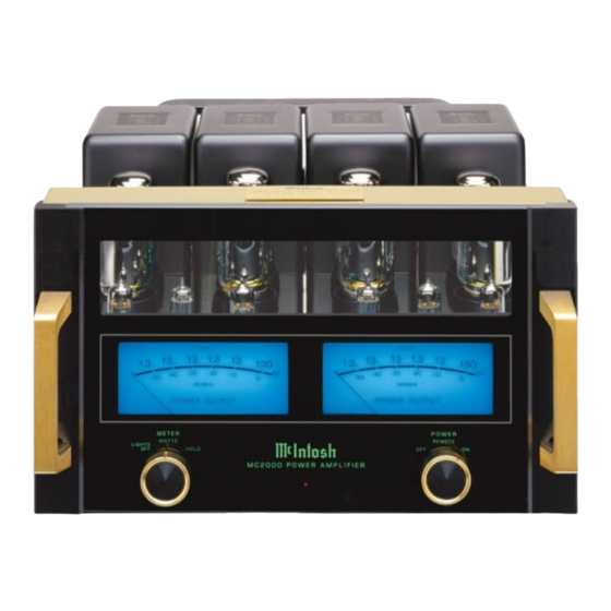
Page 3: Rear Panel
MC2000 REAR PANEL... -
Page 4: Section Location
SECTION LOCATION TOP VIEW WITH COVER REMOVED BOTTOM VIEW WITH COVER REMOVED... -
Page 5: Block Diagram
MC2000 BLOCK DIAGRAM VOLTAGE N.F.B. UNBALANCED BALANCED/ 1.2V/2.5V INPUT DRIVER OUTPUT UNBALANCED LEVEL MUTE BUFFER BUFFER UNITY RELAY RELAY GAIN LEFT OUTPUT INPUTS BIAS LEFT TRANS- BALANCED CONTROL OUTPUT FORMER UNITY INVERTING PHASE DRIVER OUTPUT BUFFER BUFFER INVERTER L. METER... - Page 6 INTERCONNECT...
- Page 7 MC2000 INPUT 2R 2L 049305...
- Page 8 MAIN 3R 3L 049306...
- Page 9 MC2000 MAIN POWER SUPPLY 3R 3L 4R 4L 049306 049308...
- Page 10 AC POWER 049309...
- Page 11 MC2000 SWITCH REMOTE 049310...
- Page 12 METER 7R 7L 049307...
- Page 13 MC2000 BIAS CONTROL METER LAMP 8R 8L 9R 9L 049311 049337 LOGO LAMP OUTPUT LAMP 11R 11L 12R 12L 049311 049312 049311...
-
Page 14: Parts List
PARTS LIST 132171 TRANSISTOR NPN 133192 IC NAND SCHMIT 2-IN X 4 144410 MF RES 1.2K 1% 1/4W R5 R10 144082 METL FILM RES 68.1 OHM 1% 1/4W R5 R6 144414 MF RES 18.2K R6 R8 PART NO. DESCRIPTION REF. NO. 144090 METAL FILM RES 1K 1% 1/4W 144417... - Page 15 MC2000 EXPLODED VIEW 1 OF 2...
-
Page 16: Exploded View And Parts List
EXPLODED VIEW PARTS LIST 2 OF 2 124071 METER 005008 SWITCH BRACKET Ref. Part Description 049357 METER ROTARY SWITCH PCB 049338 PANEL/LED LIGHT PCB 016403 FRONT GLASS 104163 M7 INTERNAL TOOTH LOCKWASHER 049334 GOLD KNOB 110004 M7 X .75 HEX CONTROL NUT 104164 FELT WASHER 004970... -
Page 17: Repacking Instructions
REPACKING INSTRUCTIONS... - Page 18 The continuous improvement of it’s products is the policy of McIntosh Laboratory Incorporated, who reserve the right to improve design without notice. Because of the constant upgrading of McIntosh products’ circuitry and components, the Company cannot insure, and does not warrant, the accuracy of the within schematic material, which is intended for information only.
Need help?
Do you have a question about the MC2000 and is the answer not in the manual?
Questions and answers
connecting the amp to interconnects how to
To connect the McIntosh MC2000 amplifier to interconnects, use only one cable type at a time—either balanced (XLR) or unbalanced (RCA)—but not both at the same time, as using both can throw off the load on the balanced connection. Select the input type using the switch on the back of the amplifier, and make sure the amplifier is turned off before changing the switch.
This answer is automatically generated