Table of Contents
Advertisement
Copyright
This publication, including all photographs, illustrations and software, is protected
under international copyright laws, with all rights reserved. Neither this manual, nor
any of the material contained herein, may be reproduced without written consent of
the author.
Version 1.0
Disclaimer
The information in this document is subject to change without notice. The manufac-
turer makes no representations or warranties with respect to the contents hereof
and specifically disclaims any implied warranties of merchantability or fitness for
any particular purpose. The manufacturer reserves the right to revise this publica-
tion and to make changes from time to time in the content hereof without obligation
of the manufacturer to notify any person of such revision or changes.
Trademark Recognition
Microsoft, MS-DOS and Windows are registered trademarks of Microsoft Corp.
MMX, Pentium, Pentium-II, Pentium-III, Celeron are registered trademarks of Intel
Corporation.
Other product names used in this manual are the properties of their respective owners
and are acknowledged.
Federal Communications Commission (FCC)
This equipment has been tested and found to comply with the limits for a Class B
digital device, pursuant to Part 15 of the FCC Rules. These limits are designed to
provide reasonable protection against harmful interference in a residential instal-
lation. This equipment generates, uses, and can radiate radio frequency energy and,
if not installed and used in accordance with the instructions, may cause harmful
interference to radio communications. However, there is no guarantee that interfer-
ence will not occur in a particular installation. If this equipment does cause harmful
interference to radio or television reception, which can be determined by turning
the equipment off and on, the user is encouraged to try to correct the interference by
one or more of the following measures:
•
Reorient or relocate the receiving antenna
•
Increase the separation between the equipment and the receiver
•
Connect the equipment onto an outlet on a circuit different from that to
which the receiver is connected
•
Consult the dealer or an experienced radio/TV technician for help
Shielded interconnect cables and a shielded AC power cable must be employed with
this equipment to ensure compliance with the pertinent RF emission limits govern-
ing this device. Changes or modifications not expressly approved by the system's
manufacturer could void the user's authority to operate the equipment.
H61H2-I5 USER MANUAL
Preface
Advertisement
Table of Contents

Related Manuals for ECS H61H2-I5


Summary of Contents for ECS H61H2-I5
- Page 1 Shielded interconnect cables and a shielded AC power cable must be employed with this equipment to ensure compliance with the pertinent RF emission limits govern- ing this device. Changes or modifications not expressly approved by the system’s manufacturer could void the user’s authority to operate the equipment. H61H2-I5 USER MANUAL...
-
Page 2: Declaration Of Conformity
Describes the motherboard Using the Motherboard Software software. Chapter 4 page 41 Provides basic trouble Trouble Shooting shooting tips. Multi-language Describes installation page 45 Quick Installation Guide motherboard components. Appendix page 79 Provides header pin definition and jumper setting. H61H2-I5 USER MANUAL... -
Page 3: Table Of Contents
Chipset Menu................21 M.I.B III(MB Intelligent Bios III) Menu........28 Boot Menu................32 Security Menu.................33 Exit Menu................34 Updating the BIOS..............35 Chapter 3 Using the Motherboard Software Auto-installing under Windows XP/7/8........37 Running Setup...............37 Manual Installation................39 ECS Utility Software (Intelligent EZ Utility)........39 H16H2-I5 USER MANUAL... - Page 4 Start up problems after prolong use..........42 Maintenance and care tips..............42 Basic Troubleshooting Flowchart.............43 Multi-language Quick Installation Guide English................45 Brazilian Portuguese..............48 Hindi....................51 French..................54 Deutsch....................57 Russian..................60 Spanish....................63 Indonesian...................66 Arabic....................69 Simplified Chinese..............72 Korean....................75 Appendix Header Pin Definition and Jumper Setting H61H2-I5 USER MANUAL...
-
Page 5: Introducing The Motherboard
Chapter 1 Introducing the Motherboard Introduction Thank you for choosing the H61H2-I5 motherboard. This motherboard is a high per- formance, enhanced function motherboard designed to support the LGA1155 socket ® for Intel Sandy/Ivy Bridge Processors for high-end business or personal desktop markets. -
Page 6: Specifications
® • LGA1155 socket for Intel Sandy/Ivy Bridge Processors • DMI 5.0GT/s • TDP: 65W (up to 77W) Note: Please go to ECS website for the latest CPU support list. ® Chipset • Intel H61 Chipset Memory • Dual-channel DDR3 memory architecture •... - Page 7 F7 hot key for boot up devices option • Supports GUI UEFI BIOS • Supports Multi-Language • Supports AC’97/HD Audio auto detect (default) • Supports PgUp clear CMOS Hotkey (Has PS2 KB Model only) Form Factor • ITX Size, 170mm x 170mm H61H2-I5 USER MANUAL...
-
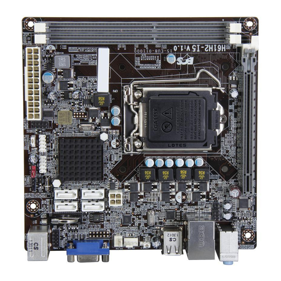
Page 8: Motherboard Components
Motherboard Components H61H2-I5 USER MANUAL... - Page 9 Front Panel USB power select jumper 16. F_USB1 Front panel USB 2.0 header 17. COM Onboard serial port header 18. ATX_POWER Standard 24-pin ATX power connector 19. DDR3_1~2 240-pin DDR3 Module slots 20. ME_UNCLOCK ME Unlock header-for factory use only H61H2-I5 USER MANUAL...
-
Page 10: I/O Ports
It can be connected to an external CD/DVD player, Tape player or other audio devices for audio input. 7. Line-out (lime) It is used to connect to speakers or headphones. 8. Microphone (pink) It is used to connect to a microphone. H61H2-I5 USER MANUAL... -
Page 11: Using Bios
When you power on the system, BIOS enters the Power-On Self Test (POST) routines. POST is a series of built-in diagnostics performed by the BIOS. After the POST routines are completed, the following message appears: Press DEL to enter SETUP H61H2-I5 USER MANUAL... -
Page 12: Resetting The Default Cmos Values
Other options lead to dialog boxes that prompt you for informa- tion. Some options (marked with a triangle ) lead to submenus that enable you to change the values for the option. Use the cursor arrow keys to scroll through the items in the submenu. H61H2-I5 USER MANUAL... -
Page 13: Bios Navigation Keys
BIOS items presented in this manual. The BIOS setup screens shown in this chapter are for reference only and may differ from the actual BIOS. Please visit the manufacture’s website for updated manual. H61H2-I5 USER MANUAL... -
Page 14: Main Menu
The Date and Time items show the current date and time on the computer. If you are running a Windows OS, these items are automatically updated whenever you make changes to the Windows Date and Time Properties utility. H61H2-I5 USER MANUAL... -
Page 15: Advanced Menu
F3:Optimized Defaults F4:Save & Exit ESC:Exit Version 2.15.1229. Copyright (C) 2012, American Megatrends, Inc. Onboard LAN Controller (Enabled) Use this item to enable or disable the Onboard LAN. Press <Esc> to return to the Advanced Menu page. H61H2-I5 USER MANUAL... -
Page 16: Pc Health Status
If you choose Silent mode, the fan speed will be auto restricted to make system more quietly. If you choose Manual mode, the fan speed will be adjust depending on users’ parameters. H61H2-I5 USER MANUAL... - Page 17 These items display the monitoring of the overall inboard hardware health events, such as CPU fan speed, CPU & DIMM voltage... etc. • CPU Fan Speed • CPU Voltage • DIMM Voltage • VTT Voltage Press <Esc> to return to the Advanced Menu page. H61H2-I5 USER MANUAL...
-
Page 18: Power Management Setup
EUP Function (Enabled) This item allows user to enable or disable EUP function. Power LED Type (Dual Color LED) This item shows the type of the power LED. Press <Esc> to return to the Advanced Menu page. H61H2-I5 USER MANUAL... -
Page 19: Acpi Setting
Execute Disable Bit [Enabled] F1:General Help Intel Virtualization Technology [Enabled] F2:Previous Values CPU C3 Report [Disabled] F3:Optimized Defaults CPU C6 Report [Enabled] F4:Save & Exit Enhanced Halt (C1E) [Enabled] ESC:Exit Version 2.15.1229. Copyright (C) 2012, American Megatrends, Inc. H61H2-I5 USER MANUAL... - Page 20 Use this item to enable or disable CPU C6(ACPI C3) report to OS. Enhanced Halt (C1E) (Enabled) Use this item to enable the CPU energy-saving function when the system is not running. Press <Esc> to return to the Advanced Menu page. H61H2-I5 USER MANUAL...
-
Page 21: Sata Configuration
SATA Port 1~4 (Not Present) This motherboard supports four SATA channel and each channel allows one SATA device to be installed. Use these items to configure each device on the SATA channel. Press <Esc> to return to the Advanced Menu page. H61H2-I5 USER MANUAL... -
Page 22: Usb Configuration
USB device at startup. If detected, the USB controller legacy mode is enabled. If no USB device is detected, the legacy USB support is disabled. Press <Esc> to return to the Advanced Menu page. H61H2-I5 USER MANUAL... -
Page 23: Super Io Configuration
This item allows you to enable or disable serial port. Device Settings (IO=3F8h; IRQ=4) This item shows the information of the device settings. Change Settings (Auto) Use this item to change device settings. Press <Esc> to return to the Super IO Configuration page. H61H2-I5 USER MANUAL... -
Page 24: Intel Smart Connect Technology
Enter : Select +/- : Change Opt. F1:General Help F2:Previous Values F3:Optimized Defaults F4:Save & Exit ESC:Exit Version 2.15.1229. Copyright (C) 2012, American Megatrends, Inc. ISCT Configuration (Disabled) Use this item to enable or disable ISCT Configuration. H61H2-I5 USER MANUAL... -
Page 25: Chipset Menu
When set to Fixed Mode, the graphics driver will reserve a fixed position of the system memory as graphics memory, according to system and graphics requirements. IGD Multi-Monitor (Disabled) This item enables or disables IGD (Internal Graphics device) multi-monitor. Press <Esc> to return to the chipset menu page. H61H2-I5 USER MANUAL... - Page 26 Intel integrated Graphics and one or two PCI-Express graphics devices under Windows 7. Step 1. Insert ECS drives DVD to run Auto setup or browse the DVD to install Intel chipset drivers, VGA and sound drivers.(If you want know the detail information, please refer to chapter 4.)
- Page 27 [64M] Device. DVMT Memory [256M] IGD Multi-Monitor [Disabled] :Select Screen :Select Item Enter : Select +/- : Change Opt. F1:General Help F2:Previous Values F3:Optimized Defaults F4:Save & Exit ESC:Exit Version 2.15.1229. Copyright (C) 2012, American Megatrends, Inc. H61H2-I5 USER MANUAL...
- Page 28 Extend desktop to this display You must select Apply before making additional changes. Disconnect this display Make this my main display Advance settings Make text and other items larger or smaller What display settings should I choose? Cancel Apply H61H2-I5 USER MANUAL...
- Page 29 Multiple displays: Extend desktop to this display You must select Apply before making additional changes. Make this my main display Advance settings Make text and other items larger or smaller What display settings should I choose? Cancel Apply H61H2-I5 USER MANUAL...
- Page 30 This item enables or disables the warning if the case is opened up, and the item below indicates the current status of the case. Chassis Opened (No) This item indicates whether the case has been opened. Press <Esc> to return to the chipset menu page. H61H2-I5 USER MANUAL...
- Page 31 F1:General Help F2:Previous Values F3:Optimized Defaults F4:Save & Exit ESC:Exit Version 2.15.1229. Copyright (C) 2012, American Megatrends, Inc. ME FW Version (8.1.0.1248) This item shows the ME version. Press <Esc> to return to the chipset menu page. H61H2-I5 USER MANUAL...
-
Page 32: M.i.b Iii (Mb Intelligent Bios Iii) Menu
F2:Previous Values 2 Core Ratio Limit F3:Optimized Defaults 3 Core Ratio Limit F4:Save & Exit 4 Core Ratio Limit ESC:Exit Intel Graphics Configuration Graphics Core Ratio Limit Graphics Voltage(1/256) Version 2.15.1229. Copyright (C) 2012, American Megatrends, Inc. H61H2-I5 USER MANUAL... - Page 33 Graphics Core Ratio Limit (22) This item allows you to control the internal GFX Turbo ratio. Graphics Voltage(1/256) (0) This item allows you to adjust the internal GFX voltage. Press <Esc> to return to the M.I.B III menu page. H61H2-I5 USER MANUAL...
- Page 34 This item specifies the row refresh cycle time. Active to Active Delay (tRRDmin) (4) This item controls the ACTIVE bank x to ACTIVE bank y in memory clock cycles. Write to Read Delay (twTR) (5) This item specifies the write to read delay time. H61H2-I5 USER MANUAL...
- Page 35 This is display-only field and displays the information of the CPU installed in your computer. Processor Speed (3100 MHz) This item shows the CPU speed. Memory Frequency (1333MHz) This item shows the momery frequency. Total Memory (2048MB(DDR3)) This item shows the total momery of DDR3. H61H2-I5 USER MANUAL...
-
Page 36: Boot Menu
Boot mode select (LEGACY) Use this item to select boot mode. Boot Option #1/#2/#3/#4/#5/#6/#7/ (Hard Disk / CD/DVD / USB/Floppy / USB CD/DVD / USB HardDisk / USB Flash / Network) These items show the boot priorities. H61H2-I5 USER MANUAL... -
Page 37: Security Menu
Secure Boot state (Disabled) This item allows you to enable or disable the secure boot state. Secure Boot (Disabled) This item is used to control the secure boot flow, it is possible only if system runs in User Mode. H61H2-I5 USER MANUAL... -
Page 38: Exit Menu
Save as User Defaults This item enables you to save the changes that you have made as user defaults. Restore User Defaults This item enables you to restore user defaults. Boot Override Use this item to select the boot device. H61H2-I5 USER MANUAL... -
Page 39: Updating The Bios
BIOS jumper, reset the jumper to protect the newly installed BIOS from being overwritten. The computer will restart automatically. This concludes Chapter 3. Refer to the next chapter for information on the software supplied with the motherboard. H61H2-I5 USER MANUAL... - Page 40 Memo H61H2-I5 USER MANUAL...
-
Page 41: Using The Motherboard Software
Click Setup. The installation program begins: The following screens are examples only. The screens and driver lists will be different according to the motherboard you are installing. The motherboard identification is located in the upper left-hand corner. H61H2-I5 USER MANUAL... - Page 42 Windows 8 will show the following screen after system restart, you must select “Desktop” in the bottom left to install the next driver. H61H2-I5 USER MANUAL...
-
Page 43: Manual Installation
ECS Utility Software (Intelligent EZ Utility) ECS Intelligent EZ Utility provides friendly interfaces under Windows O.S, which makes your computing more easily and conveniently. These software(s) are subject to change at anytime without prior notice. Please refer to the support disk for available software. - Page 44 Just select the one you prefer and start to download and install the drivers. eBLU ECS eBLU utility makes BIOS update faster and easier. eBLU will list the latest BIOS with a default check-mark. Click”install” button to install. H61H2-I5 USER MANUAL...
-
Page 45: Trouble Shooting
Before calling for technical support or returning for warranty, this chapter may help to address some of the common questions using some basic troubleshooting tips. You may also log onto our ECS website for more information: http:// www.ecs.com.tw/ECSWebSite/Support/Support_FAQ.aspx?MenulD=49& childid=M 49&LanlD=0 a) System does not power up and the fans are not running. -
Page 46: Start Up Problems After Prolong Use
5. Check whether there is any bulked up electrolytic capacitor or abnormal component. Please logo onto our ECS website: http://www.ecs.com.tw/ECSWebSite/Support/ Technical_Support_List.aspx?MenuID=50&LanID=0 for more information. Maintenance and care tips Your computer, like any electrical appliance, requires proper care and maintenance. - Page 48 Memo H61H2-I5 USER MANUAL...
- Page 49 Hardware Guide Steps Step1. Ins of the CPU and CPU Cooler: 1-1. Pull up the lever away from the 1-2. Align the CPU cut edge with the socket. indented edge of the CPU socket. Gently place the CPU into correct posi on. Apply an even layer of thermal grease on the surface of CPU.
- Page 50 Step4. Installation of storage devices: 4-1. Please remove the front cover and 4-2. Place the storage devices (IDE/ 5.25’’ plate from the case. SATA/FDD) in its position within the case and secure the device with screws. Step5. Case Preparation and Installation of Power Supply: Remove both sides and the lid of the case, and then install the power supply with screws.
- Page 51 Step 8: Connec g ports on the case: Once the steps above have been completed, please connect the peripherals such as the keyboard, mouse, monitor, etc. Then, connect the power and turn on the system. Please install all the required Please install all peripheral devices.
- Page 52 Manual de Instalação de Hardware Etapas para instalação Passo 1. Instalação da CPU e da CPU Refrigeração (Cooler): 1-1. Puxe a alavanca para fora do 1-2. Alinhe o lado da CPU com o lado soquete. correto do soquete do processador. Delicadamente, coloque o processador na posição correta.
- Page 53 4-1. 4-2. placa 5,25'' do gabinete. armazenamento (IDE/ SATA /FDD) no com parafusos. Passo 5. Processo de Preparação e Instalação da Alimentação do gabinete: Remova ambos os lados e a tampa do gabinete e instale a fonte de alimentação com parafusos. É...
- Page 54 Após as etapas acima terem sido completadas, por favor conectar os periféricos como o teclado, o mouse, monitor, etc. Em seguida, conecte a alimentação e ligue o sistema. Por favor, instale 8-1. Conexão de teclado 8-2. Conexão da impressora 8-3. Conexão do monitor 8-4.
- Page 55 1 CPU 1-1. 1-2. CPU . CPU 1-3. CPU 1-4. CPU CPU_FAN 2-1. DIMM 2-2. DIMM 3-1. 3-2.
- Page 56 4-1. 5.25’’ 4-2. (IDE/SATA/FDD) 300W SATA SATA SATA SATA . 4- ATX_12V 4- . 4- ATX_12V...
- Page 57 8-1. 8-2. 8-3. 8-4. 8-5. 8-6. BIOS ( BIOS (POST) <DEL> POST CMOS BIOS “Load BIOS Enter...
- Page 58 1-1. Ecartez le levier du socket. 1-2. Alignez le bord coupé du CPU avec le bord correspondant sur le socket du CPU. Placez soigneusement le CPU dans la bonne de pâte thermique sur la surface du CPU. 1-3. Tournez et appuyez sur la 1-4.
- Page 59 4-1. 4-2. Placez les périphériques de stockage ez-les avec des vis. insu sante peut entraîner une instabilité de démarrage. d'extension dans le logement. Appuyez fermement sur la carte pour vous assurer qu'elle est complètement insérée a. Connectez le disque dur SATA à son câble SATA au périphérique SATA broches...
- Page 60 Une fois que les étapes ci-dessus ont été e ectuées, connectez les périphériques tels que le clavier, la et allumez le système. Installez tous les logiciels requis. Installez tous les périphériques. 8-1. Connexion du clavier 8-2. Connexion de l'imprimante 8-3. Connexion du moniteur 8-4.
- Page 61 1-1. Lösen Sie den Hebel vom Kunststo abdeckung und richten Sie die CPU-Sockel. Kerbe der CPU mit der entsprechenden Stelle des CPU-Sockels aus. Legen Sie die Tragen Sie eine erbsengroße Menge der Ober äche der CPU auf. 1-3. Lösen Sie durch eine Drehung die 1-4.
- Page 62 4-2. Installieren Sie die Speichergeräte (IDE/SATA-Wechseldatenträger-Laufwerk(e) Abdeckung des Gehäuses und eine 5,25''-Abdeckung aus der vorderen entsprechenden Schächte hineinschieben Abdeckung des Gehäuses. des Gehäuses und platzieren Sie dann das Netzteil an der Es wird empfohlen, ein Netzteil mit einer Leistung von mehr als 300W zu verwenden.
- Page 63 haben, können Sie die Peripheriegeräte wie etwa Tastatur, Maus, Monitor, usw. anschließen. Stecken Sie dann das eine Ende des Netzkabels hinten in das Netzteil und das andere Ende in eine Steckdose. Nach Anschluss der unten genannten Peripheriegeräte können Installieren Sie nun die Peripheriegeräte. 8-1.
- Page 64 1-1. 1-3. 1-4. CPU_FAN. 3-1. 3-2.
- Page 65 4-2. (IDE/ 4-1. 5.25’’ SATA/FDD) SATA SATA SATA SATA ATX_12V. ATX_12V.
- Page 66 8-1. 8-2. 8-3. 8-4. 8-5. 8-6. BIOS BIOS ( BIOS POST ( <DEL> CMOS). BIOS “Load Default CMOS BIOS Enter...
- Page 67 Guía de instalación del hardware Pasos para realizar la instalación Paso 1. Instalación de la CPU y sistema de refrigeración de la CPU: 1-1. Tire de la palanca hacia arriba, 1-2. Alinee el borde recortado de la CPU con el borde dentado del zócalo de la CPU. apartándola del zócalo.
- Page 68 4-1. Quite la cubierta frontal y la placa de 5,25 pulg. de la carcasa. (IDE/SATA/FDD) en su lugar dentro de la carcasa y asegurelos con tornillos. Paso 5. Preparación de la carcasa e instalación de la fuente de alimentación: instale la fuente de alimentación con tornillos. proporcione más de 300W de potencia.
- Page 69 Paso 8. Conexión de los puertos en la carcasa: Una vez completados los anteriores pasos, conecte los periféricos como el teclado, el mouse, monitor, etc. A 8-1. Conexión del teclado 8-2. Conexión de la impresora 8-3. Conexión del monitor 8-4 . Conexión de los altavoces 8-5.
- Page 70 Panduan Pemasangan Perangkat Keras Langkah-Langkah Pemasangan Langkah 1. Pemasangan CPU dan Pendingin CPU: 1-1. Tarik tuas dari soket. 1-2. Luruskan tepi pemisah CPU dengan tepi bertakik dari soket CPU. Pasang CPU secara perlahan pada posisi yang tepat. Oleskan lapisan gemuk termal secara merata pada permukaan CPU.
- Page 71 Langkah 4. Pemasangan perangkat penyimpanan: 4-1. Harap lepaskan penutup depan dan 4-2. Pasang perangkat penyimpanan pelat 5,25’’ dari casing. (IDE/SATA/ FDD) ke dalam posisinya di dalam casing dan kencangkan perangkat dengan sekrup. Langkah 5. Menyiapkan Casing dan Pemasangan Catu Daya: Lepaskan kedua sisi dan dan tutup casing, lalu pasang catu daya dengan sekrup.
- Page 72 Langkah 8. Menyambungkan port pada casing: Setelah langkah-langkah di atas selesai, harap monitor, dll. Lalu sambungkan daya dan nyalakan sistem. Harap pasang semua perangkat lunak yang dibutuhkan. Harap pasang semua perangkat peripheral. 8-1. Sambungan keyboard 8-2. Sambungan printer 8-3. Sambungan monitor 8-4.
- Page 73 .(CPU_FAN .(DIMM...
- Page 74 IDE/SATA/FDD 5.25 SATA SATA SATA SATA...
- Page 75 (BIOS BIOS POST CMOS Enter...
- Page 76 硬件安装指南 安装步骤 1.安装CPU和CPU风扇: 1-1. 松 开 C P U 插 槽 旁 的 固 定 杆 , 向 1-2. 将 C P U 边 缘 的 缺 口 对 准 C P U 插 槽 上 拉 固 定 杆 , 并 掀 开 插 槽 上 的 保 标...
- Page 77 4-1. 移除机箱的前盖以及5.25吋硬盘挡 4-2. 将储存装置放入机箱中对应位置, 板。 并以螺丝固定。 取下机箱侧面和顶部的挡板,安装好电源装置后,用螺丝 固定。 建议使用供电300瓦以上的电源供应器,以避免电 源不足导致无法开机。 移除机箱后面的扩充金属挡板,确认扩充卡完全插入扩展 槽后,重新拧上螺丝。 7.连接电源线与电源接头: a. 将SATA电缆连接至SATA 硬盘 b. 将SATA电源接头连接至SATA设备 c. 连接24针电源线与电源接头 d. 连接4针电源线与电源接头 请注意电源接头与电源线必须完全扣合。 4针电源接头提供CPU电源。其电源接头与 电源线必须完全扣合。...
- Page 78 8.连接机箱端口: 当上述安装步骤完成后,请开始安装键盘,鼠标, 显示器等外围设备,然后连接电源并启动系统。 请安装好所需的软件。 安装所有外围设备: 8-1. 连接键盘 8-2. 连接打印机 8-3. 连接显示器 8-4. 连接喇叭 8-5. 连接电源 8-6. 连接鼠标 注意: 在安装尚未完成以前请勿开机,以免造成硬件设备毁损。 BIOS使用设定 BIOS程序画面会显示系统配置,同时提供操作选项让您设定系统参数。当开机时, (POST),请点击 <DEL> 或 F2 进入BIOS程序设定。第一 BIOS会进行开机自我测试 次开机时,POST画面可能会显示 信息,请进入BIOS选单 并选择 将BIOS重新设定为默认值 (更换CPU或内存等硬件 变更也可能会出现此信息)。The BIOS (Basic Input and Output System) BIOS 操作功能键说明: 键...
- Page 79 하드웨어 설치 가이드 단계별 설치 방법 쿨러 설치하기: 1단계. CPU와CPU 1-1. 소켓에서 레버를 뽑아 냅니다. 1-2. CPU 끝 부분을 CPU 소켓의 들어간 끝 부분에 맞춥니다. CPU를 정확한 위치에 살며시 위치시킵니다. CPU의 표면에 써멀 그리스를 고르게 도포합니다. 1-3. 패스너를 돌려 CPU 팬을 마더보 1-4.
- Page 80 4단계. 저장 장치 설치하기: 4-1. 전 면 커 버 와 5 . 2 5 ’ ’ 플 레 4-2. 저 장 장 치 ( I D E / S A T A / F D D ) 를 이 트 를 케 이 스 에 서 제 거 합 니 다 . 케...
- Page 81 8단계. 케이스의 포트 연결하기: 일단 위의 단계들이 완료되면, 키보드, 마우스, 모니터 등과 같은 주변기기들을 연결합니다. 그런 후에, 전원을 연결하고 시스템을 켭니다. 모든 필수 소프트웨어를 설치합니다. 모든 주변 기기를 설치합니다. 8-2. 프린터 연결 8-1. 키보드 연결 8-4. 스피커 연결 8-3. 모니터 연결 8-5.
- Page 82 Memo H61H2-I5 USER MANUAL...
- Page 83 Data Terminal Ready Data Set Ready F_USB1~2 USB Port B (+) USB Port B (-) Ground Power +5V Power +5V USB Port A (-) Ground USB Port A (+) VGA_HEADER VGA_VSYNC VGA_DDC_DATA VGA_DDC_CLK VGA_B VGA_VCC VGA_G VGA_HSYNC VGA_R H61H2-I5 USER MANUAL...
- Page 84 3. CLR_CMOS Jumper 1-2: NORMAL 2-3: CLEAR CMOS Before clearing the CMOS, make sure to turn off the system. CLR_CMOS 4. USBPWR_R (Rear USB PS/2 Power Select Jumper) 5. USBPWR_F (Front Panel USB Power Select Jumper) 5VSB (Default) H61H2-I5 USER MANUAL...
Need help?
Do you have a question about the H61H2-I5 and is the answer not in the manual?
Questions and answers