Table of Contents
Advertisement
Quick Links
SAVE THESE INSTRUCTIONS:
purchased. You may need to refer to these instructions at a later date.
CAUTION:
To reduce the risk of injury, charge only lead acid type rechargeable batteries (Lead accumulator battery). Other types of
batteries may burst, causing personal injury and property damage.
WARNING-RISK OF EXPLOSIVE GASES
WORKING IN THE VICINITY OF A LEAD-ACID OR OTHER AUTOMOTIVE BATTERY IS DANGEROUS. BATTERIES GENERATE
EXPLOSIVE GASES DURING NORMAL BATTERY OPERATION. FOR THIS REASON, IT IS OF UTMOST IMPORTANCE THAT EACH
TIME, BEFORE USING YOUR CHARGER, YOU READ THIS MANUAL AND FOLLOW THE INSTRUCTIONS EXACTLY.
An extension cord should not be used unless absolutely necessary. Use of an improper extension cord could result in the risk of fire and
electric shock. If an extension cord must be used, make sure:
a.
That it has a protective conductor (earthed) and a minimum cross section of 1.5mm
b.
For industrial and agricultural usage, use only electrical extension cords approved for these operations.
PREPARING TO CHARGE:
1.
a.
Be sure the area around the battery is well ventilated while the battery is being charged.
b.
Clean the battery terminals.
c.
Add distilled water in each cell until the battery acid reaches the level specified by the battery manufacturer. The normal level is
usually 1 cm above the lead plates.
d.
Determine the voltage of the battery by referring to the vehicle owner's manual and make sure that the output voltage selector
switches are set at the correct voltage. If the charger has an adjustable charge rate, charge the battery initially at the charger's
lowest rate for the battery.
DC CONNECTION PRECAUTIONS
2.
a.
Connect and disconnect the DC output clamps only after setting the AC Power switch to the « F » (OFF) position and removing the
AC cord from the electric outlet. Never allow the clamps to touch each other.
b.
When attaching a clamp to a battery post, twist or rock the clamp back and forth several times to make a good connection.
FOLLOW THESE STEPS WHEN CONNECTING THE BATTERY
3.
a.
Check the polarity of the battery posts. The Positive (POS,P,+) battery post usually has a larger diameter then the Negative (NEG,N,-
) battery post.
b.
Determine which post of the battery is grounded (connected to the chassis). If the negative post is grounded to the chassis (as in
most vehicles), see paragraph 4c. If the positive post is grounded to the chassis, see paragraph 4d.
c.
For a Negative ground vehicle, double check the polarity of the battery terminals. Connect the Positive (Red) clamp from the battery
charger to the Positive (POS,P,+) ungrounded post of the battery. Connect the Negative (Black) clamp to the vehicle chassis, a
heavy gauge metal part of the frame or the engine block, away from the battery. Do not connect the clamp to the carburetor, fuel
lines or sheet metal part of the frame.
d.
For a Positive ground vehicle, double check the polarity of the battery terminals. Attach the Negative (Black) clamp to the Negative
(NEG,N,-) ungrounded post of the battery. Attach the Positive (Red) clamp to the vehicle chassis, a heavy gauge metal part of the
frame or the engine block, away from the battery. Do not connect the clamp to the carburetor, fuel lines or sheet metal part of the
frame.
e.
When disconnecting the charger, follow these precautions:
Turn the AC Power Switch to the « F » (OFF) position.
!
Disconnect the AC cord.
!
Remove the clamp from the vehicle chassis.
!
And then remove the clamp from the battery terminal.
!
f.
See section 4, LENGTH OF CHARGE, for information on length and rate of charge.
g.
A marine (boat) battery must be removed and charged on shore. To charge it on-board requires equipment specially designed for
marine use.
LENGTH OF CHARGE
4.
a.
Use a temperature compensating hydrometer or a voltmeter to determine the State of Charge of the battery. Do not charge a battery
that is over 75% charged or if the battery is determined to be defective. Refer to the STATE OF CHARGE TABLE.
b.
Determine the Battery Size,(Small, Medium or Large). Refer to the BATTERY SIZE table.
c.
Refer to the CHARGE RATE Vs MINUTES CHARGE table to determine the recommended length of charge for the battery based on its
size, state of charge and the charging amperes.
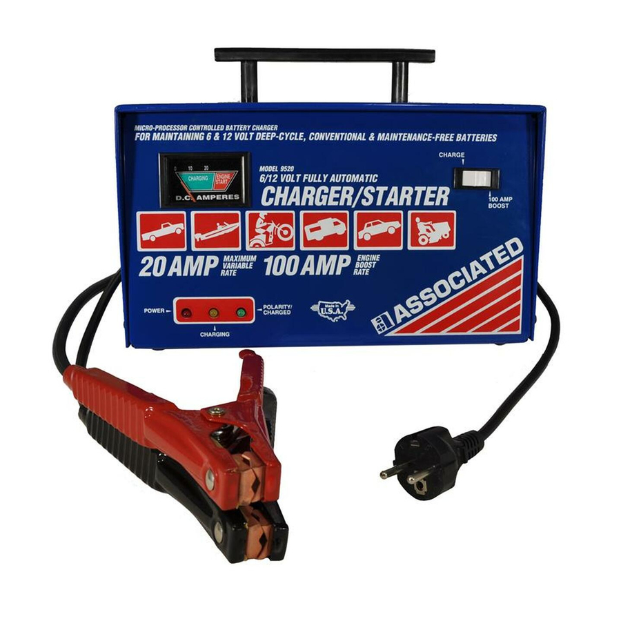
MODEL 9520 & 9520GS
6/12 VOLT, 0-20 AMP - BATTERY CHARGER
OWNER'S MANUAL
IMPORTANT SAFETY INSTRUCTIONS
This manual contains important safety and operating instructions for the battery charger you have
2
in accordance with local electrical safety codes.
13
Advertisement
Table of Contents

Related Manuals for Associated Equipment 9520


Summary of Contents for Associated Equipment 9520
-
Page 1: Important Safety Instructions
Determine the Battery Size,(Small, Medium or Large). Refer to the BATTERY SIZE table. Refer to the CHARGE RATE Vs MINUTES CHARGE table to determine the recommended length of charge for the battery based on its size, state of charge and the charging amperes. MODEL 9520 & 9520GS OWNER'S MANUAL IMPORTANT SAFETY INSTRUCTIONS This manual contains important safety and operating instructions for the battery charger you have in accordance with local electrical safety codes. - Page 2 should be used for this reading. Discontinue charging if the battery begins to gas excessively or when the temperature of the electrolyte reaches approximately 59 OPERA TING INSTRUCTIONS CONTINUOUS RED LIGHT - Indicates AC power is on. CONTINUOUS GREEN LIGHT - Indicates correct connection. If when battery is connected, the green light does not light, check for proper polarity or poor connections.
-
Page 3: Wiring Diagram
meter indicates low charging current. NOTES: If the charger is connected to a battery which will not accept a charge, the charging cycle will end and the GREEN light will blink. If the charger is connected to a fully charged battery the charger will shut off and the GREEN light will blink. If the clamps are removed during the battery test sequence the charger will shut off and the GREEN light will blink. -
Page 4: Maintenance Instructions
Handle ........610619 Cabinet Top 9520 ......610755 Cabinet Top 9520GS . - Page 5 ENG-TABL.PLT CHARGE RATE TABLE - ENGLISH 37-511E.PLT WIRING DIAGRAM YAH1220 A4385.PLT EXPLODED VIEW 9520 DOCUMENT LISTING 027-0550 - 9520 / 9520GS OWNERS MANUAL DOC No. FILENAME 27-550G.MAN GERMAN LANGUAGE SECTION PG 1 - 4 27-550D.MAN DUTCH LANGUAGE SECTION PG 5 - 8 27-550F.MAN...
Need help?
Do you have a question about the 9520 and is the answer not in the manual?
Questions and answers