Table of Contents
Advertisement
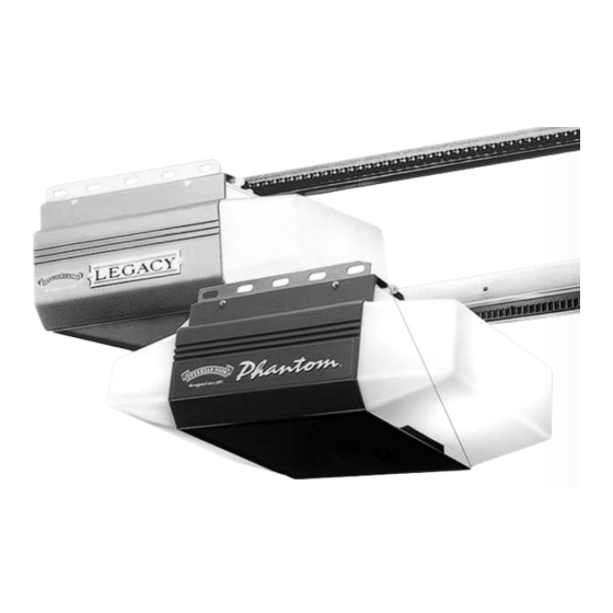
Automatic
Chain Drive/Belt Drive
Garage Door Operator
System
Complete with
SERIES II Electronics
Operator MUST be installed with the included SERIES II Wall Control!
Self-diagnostic Electronic Sensory Protection System
BEAM SYSTEM) MUST Be Installed To Close Door!
Owner's Manual
SAVE FOR FUTURE REFERENCE
Customer Service
C A L L : 1 - 8 0 0 - 9 2 9 - 3 6 6 7
O R V I S I T W W W . O V E R H E A D D O O R . C O M
AUTOMATIC GARAGE DOOR OPERATOR SYSTEMS
HANG MANUAL NEAR YOUR WALL CONTROL
¤
Remote Control and
(SAFE-T-
CD Series
CDB Series
TABLE OF CONTENTS
SECTION
SAFETY INFORMATION . . . . . . . . . . . . . . . . . . . . . . . . . . . . . . . . . . . . . . . . . . . . . . 2-4
PARTS IDENTIFICATION . . . . . . . . . . . . . . . . . . . . . . . . . . . . . . . . . . . . . . . . . . . . . . 5-6
1
OPERATOR ASSEMBLY . . . . . . . . . . . . . . . . . . . . . . . . . . . . . . . . . . . . 10-11
1A Channel and Power Head Assembly . . . . . . . . . . . . . . . . . . .10
1B Rail and Power Head Assembly . . . . . . . . . . . . . . . . . . . . .10-11
2
DETERMINE DOOR TYPE AND MOUNTING METHOD . . . . . . . . . . . 11
2A Installation on Track Guided Doors . . . . . . . . . . . . . . . . 12-14
2B Installation on Trackless Doors . . . . . . . . . . . . . . . . . . . . 15-17
SAFE-T-BEAM ® (STB) SYSTEM INSTALLATION . . . . . . . . . . . . . . . 18-19
3
Self-diagnostic "STB" System Troubleshooting . . . . . . . . . . . . 19
4
WALL CONTROL INSTALLATION . . . . . . . . . . . . . . . . . . . . . . . . . . . . . . . 20
5
CONNECT OPERATOR TO POWER . . . . . . . . . . . . . . . . . . . . . . . . . . . . . 21
6
MAIN LIMIT SWITCH SETTINGS . . . . . . . . . . . . . . . . . . . . . . . . . . . . . . . 22
OPERATION
7
FORCE ADJUSTMENT . . . . . . . . . . . . . . . . . . . . . . . . . . . . . . . . . . . . . . . . 23
Contact Reverse . . . . . . . . . . . . . . . . . . . . . . . . . . . . . . . . . . . . . . . . . 23
8
FINE LIMIT SWITCH ADJUSTMENTS . . . . . . . . . . . . . . . . . . . . . . . . . . . 24
9
REMOTE CONTROLS . . . . . . . . . . . . . . . . . . . . . . . . . . . . . . . . . . . . . . 24-25
10 BATTERY & VISOR CLIP INSTALLATION . . . . . . . . . . . . . . . . . . . . . . . . 25
11 LIGHT BULB AND LENS INSTALLATION . . . . . . . . . . . . . . . . . . . . . . . . 26
MAINTENANCE . . . . . . . . . . . . . . . . . . . . . . . . . . . . . . . . . . . . . . . . . . . . . . . . . . . . . . .27
TROUBLESHOOTING GUIDE . . . . . . . . . . . . . . . . . . . . . . . . . . . . . . . . . . . . . . . . . . 28
WIRING DIAGRAM . . . . . . . . . . . . . . . . . . . . . . . . . . . . . . . . . . . . . . . . . . . . . . . . . . . 29
ACCESSORIES . . . . . . . . . . . . . . . . . . . . . . . . . . . . . . . . . . . . . . . . . . . . . . . . . . . . . . . .30
WARRANTY 32
3507635556
PAGE
Advertisement
Table of Contents
Troubleshooting

Related Manuals for Overhead door CD Series


Summary of Contents for Overhead door CD Series
-
Page 1: Table Of Contents
3507635556 CD Series CDB Series ¤ Automatic Chain Drive/Belt Drive TABLE OF CONTENTS SECTION PAGE Garage Door Operator SAFETY INFORMATION ..........2-4 PARTS IDENTIFICATION . - Page 2 “Do-It-Yourself ” installation. Any questions should be directed to the Overhead Door Corporation or an authorized Overhead Door Dealer. ( The issue numbers below refer to the circled numbers in the illustrations on page 3.
- Page 3 TYPICAL SECTIONAL DOOR INSTALLATION TYPICAL ADDED SUPPORT HEADER BRACKET BRACKET MOUNTING BOARD BRACES 36” POWER CORD 120V GROUNDED OUTLET EXTENSION SPRING TORSION SPRING SAFE-T-BEAM ® TYPICAL (TRACKLESS) 1-PIECE DOOR INSTALLATION TYPICAL (TRACK GUIDED) 1-PIECE DOOR INSTALLATION ONE-PIECE DOOR SECTIONAL DOOR...
-
Page 4: Safety Information
SAFETY INFORMATION OPERATOR INSTALLATION OVERVIEW OF IMPORTANT POTENTIAL HAZARDS INSTALLATION INSTRUCTIONS Garage doors are large, heavy objects that move with the help of springs under high tension and electric motors. Since moving objects, springs under tension, and electric motors can cause injuries, your safety and the safety of others depend on WARNING WARNING you reading the information in this manual. -
Page 5: Parts Identification
PARTS IDENTIFICATION FOR HELP—1-800-929.3667 OR OVERHEADDOOR.COM NUSTBSENDSENS-2 remotes vary by model NUSTBSENDSENS-1 NOTE: Accessories vary by model. FASTENERS - Shown full size. See Parts List for description. 1/4”-20 x 3/4” Insulated Staple Self-Drilling Screw Bolt, #10-24 x 1/2” Wall Console Screw Pan Head Screw #6 x 1-1/4”... -
Page 6: M.o.v. Assembly
PARTS IDENTIFICATION FOR HELP—1-800-929.3667 OR OVERHEADDOOR.COM Phantom Power Head (DC) Combined Parts List Item Part Name Item Part Name Item Part Name Lens Rectifier Board Assembly Capacitor Front Cover Fuse (F1), UL Capacitor Clamp Side Cover (by series/model) Fuse (F2), UL Screw, #10-24 x 1/2”, Slot HH Sf-Tap Top Plate Assembly Limit Gear Shroud... - Page 7 PARTS IDENTIFICATION FOR HELP—1-800-929.3667 OR OVERHEADDOOR.COM Legacy Power Head (AC) 52 64 Item Part Name Main Drive Worm Screw, #8 x 3-1/8” Slot HH, Sf Tap Limit Switch Plate Screw, #6 x 3/8” Phillips w/Wshr, Sf Tap Screw, #4 x 5/8”, Slot HH w/Wshr, Sf Tap...
- Page 8 PARTS IDENTIFICATION FOR HELP—1-800-929.3667 OR OVERHEADDOOR.COM Channel 96 89 Combined Parts List Item Part Name Item Part Name Item Part Name Belt & Bullet Assembly - 7’6” Door Chain Bullet Channel - 7’6” Door (128” LG) (Belt Models Only) Belt Bullet Channel - 8’...
- Page 9 PARTS IDENTIFICATION FOR HELP—1-800-929.3667 OR OVERHEADDOOR.COM Rail Item Part Name Item Part Name Boom Support Kit (not shown) Screw, 1-1/4” Phillips HH Safety & Maintenance Guide Insulated Staples Emergency Release Tag (Tri-L) Entrapment WARNING Label Wire Rail (L=112.475”) Screw, 5/16”-18 x 3/4” Screw, 5/16”...
-
Page 10: Operator Assembly
OPERATOR ASSEMBLY FOR HELP—1-800-929.3667 OR OVERHEADDOOR.COM OPEN BLUE PARTS BAG Toward Door Toward Power Head Screws for attaching light cover are included in this bag. Please set aside for use later. Carriage 1. Attach emergency release knob cord (Fig. 1-1). •... -
Page 11: Installation
5. Fasten rail to power head. • Align mounting holes of sprocket saddle, rail and power head frame. • Insert the two (2) 5/16” x 1/2” hex head screws[112], then two (2) No. 10-24 x 1/2” hex head screws [69]. •... -
Page 12: Installation On Track Guided Doors
Alternate Mounting Methods NOTE: Materials for mounting are not included Angle Iron Method Conduit Method FOR TRACK GUIDED DOORS – FOR TRACKLESS DOORS GO TO PAGE 15 – Line “V” (Vertical Center Line of Line “H” Can Be Door) Drawn Above WARNING Spring Line “H”... - Page 13 CAUTION Line “V” “B” Header bracket must be fastened to garage fram- ing. Do Not fasten to drywall, particle board, plas- Header Bracket “A” ter or other such materials. Line “H” 3. Install header bracket (Fig. 2-3) • Place bracket so: –...
-
Page 14: Safe-T-Beam ® (Stb) System Installation
“V” “V” “V” Top of Door Dessus de la porte Top of Door Top of Door Top of Door Dessus de la porte “V” “V” “V” [ 79 ] [ 96 ] [ 96 ] [ 79 ] [ 96 ] [ 79 ] Sectional doors One-piece doors... -
Page 15: Installation On Trackless Doors
FOR TRACKLESS DOORS FOR HELP—1-800-929.3667 OR OVERHEADDOOR.COM WARNING Line “V” (Vertical centerline of door) TABLE A • Do Not try to remove, repair or adjust springs or anything to which door spring parts are fastened, Door header such as, wood blocks, steel brackets, cables or Top of door other like items. - Page 16 5. Install door braces “V” “V” (See CAUTION below). Top of Door Top of Door Top of Door CAUTION Dessus de la porte Dessus de la porte Doors made of masonite, lightweight wood, fiberglass, and “V” “V” metal must be properly braced before mounting [ 96 ] an operator.
- Page 17 OPEN YELLOW PARTS BAG Straight door arm CAUTION [ 91 ] Mounting bracket must be fastened to garage fram- Bolt, 3/8-16 x 7/8” ing. Do Not fasten to drywall, particle board, plaster Curved door arm or other such materials. [ 92 ] 9.
- Page 18 SAFE-T-BEAM ® INSTALLATION FOR HELP—1-800-929.3667 OR OVERHEADDOOR.COM WARNING There should be no electrical power to the operator while installing Safe-T-Beam ® System wires. If you have plugged in the power cord —UNPLUG IT NOW. NOTE: The operator will not close the door automatically unless the Safe-T-Beam ®...
-
Page 19: Self-Diagnostic "Stb" System Troubleshooting
CAUTION Staples which are too tight can cut or pinch wires. Cut or pinched wires can cause the STB System to stop working. When using the insulated sta- ples, make sure you fasten them only as tightly as needed to hold the wire snugly. •... -
Page 20: Wall Control Installation
CLOSE OPEN TO SET LIMITS LIMIT ADJUSTMENT WALL CONTROL INSTALLATION FOR HELP—1-800-929.3667 OR OVERHEADDOOR.COM WARNING Power head White terminals Power cord must be unplugged before attaching Striped Wall wires. Be sure wire ends do not touch each other or button terminals other terminals. -
Page 21: Connect Operator To Power
CONNECT OPERATOR TO POWER FOR HELP—1-800-929.3667 OR OVERHEADDOOR.COM WARNING To reduce the risk of electrical shock, this equipment has Grounded a grounding type plug that has a third (grounding) outlet pin. This plug will only fit into a grounding type outlet. If the plug does not fit into the outlet, contact a qualified electrician to install the proper... -
Page 22: Main Limit Switch Settings
OPEN MORE MORE CLOSE PUSH CLOSE OPEN TO SET LIMITS LIMIT ADJUSTMENT MAIN LIMIT SWITCH SETTINGS FOR HELP—1-800-929.3667 OR OVERHEADDOOR.COM WARNING Door opens rapidly. • Keep path clear. PUSH CLASS 2 • Position ladder to the side of power head so it TO SET OPEN MORE... -
Page 23: Force Adjustment
FORCE ADJUSTMENT FOR HELP—1-800-929.3667 OR OVERHEADDOOR.COM WARNING Adjust your door operator so that minimum force is needed to operate door. CLASS 2 Position ladder to the side of the power head so that PUSH it is clear of all moving parts of the power head, rail OPEN BUTTON CLOSE... -
Page 24: Fine Limit Switch Adjustments
FINE LIMIT SWITCH ADJUSTMENT FOR HELP—1-800-929.3667 OR OVERHEADDOOR.COM During the following steps, the motor protector may open. Wait about 20 minutes for protector to reset. 1. Adjusting the “OPEN” limit switch (Fig. 8-1). MORE MORE • Run door to open position by pushing wall control. •... -
Page 25: Remote Controls
• Press and release a remote control button. – LED on power head stops blinking. • Press and release same remote button again. Radio sig- – LED goes out. Remote is now programmed. nal indica- 2. Program multi-button remote control •... -
Page 26: Light Bulb And Lens Installation
LIGHT BULB AND LENS INSTALLATION FOR HELP—1-800-929.3667 OR OVERHEADDOOR.COM 1. Install light bulb(s) into socket(s). Bend tabs up (2) Do Not use short neck bulb(s). • Use bulb(s) rated for: – rough service. Slotted tabs – vibration. – appliances. • 100 watt maximum. 2. -
Page 27: Maintenance
MAINTENANCE FOR HELP—1-800-929.3667 OR OVERHEADDOOR.COM MONTHLY MAINTENANCE DOOR SPRINGS and DOOR HARDWARE CONTACT REVERSE • Do not operate garage door automatically or • Close door on a 2 by 4 board laid flat on the floor manually if springs are broken. CONTACT A in the center of the garage doorway. -
Page 28: Troubleshooting Guide
TROUBLESHOOTING GUIDE FOR HELP—1-800-929.3667 OR OVERHEADDOOR.COM Use this guide to correct problems with your door opera- tor. If these solutions do not work, call Customer Service. CAUTION Use only with included SERIES II wall control Use of any other wall control can cause the door to operate unexpectedly and the light not to work. -
Page 29: Wiring Diagram
WIRING DIAGRAM FOR HELP—1-800-929.3667 OR OVERHEADDOOR.COM CAUTION Opening cover could cause electrical shock. ( Phantom Motor ) ( Legacy Motor ) -
Page 30: Accessories
2-Button Remote Control with CodeDodger ® Universal Conversion Kit ® 3-Button Remote Control with CodeDodger 60 WATT Light Bulb ® 3-Button Mini Remote Control withCodeDodger Emergency Release Kit OverHead Door Corp 22790 Lake Park Blvd. Alliance, Ohio 44601 Call: 1.800.929.3667 Web: www.overheaddoor.com... - Page 31 INSTALLATION NOTES FOR HELP—1-800-929.3667 OR OVERHEADDOOR.COM CONTACT NUMBERS NAME COMPANY NUMBER NAME COMPANY NUMBER NAME COMPANY NUMBER NAME COMPANY NUMBER NAME COMPANY NUMBER NAME COMPANY NUMBER...
-
Page 32: Warranty
22790 Lake Park Blvd. • Alliance, Ohio USA • 44601 Overhead Door Corporation (“ODC”) warrants to the original purchaser of the garage door opener as follows: Model 496 - Motor 5 Years and all other parts 3 years. Model 696 - Motor Lifetime* and all other parts 5 years.