Sign In
Upload
Manuals
Brands
YASKAWA Manuals
Computer Hardware
VIPA System MICRO M13-CCF0000
YASKAWA VIPA System MICRO M13-CCF0000 Manuals
Manuals and User Guides for YASKAWA VIPA System MICRO M13-CCF0000. We have
1
YASKAWA VIPA System MICRO M13-CCF0000 manual available for free PDF download: Manual
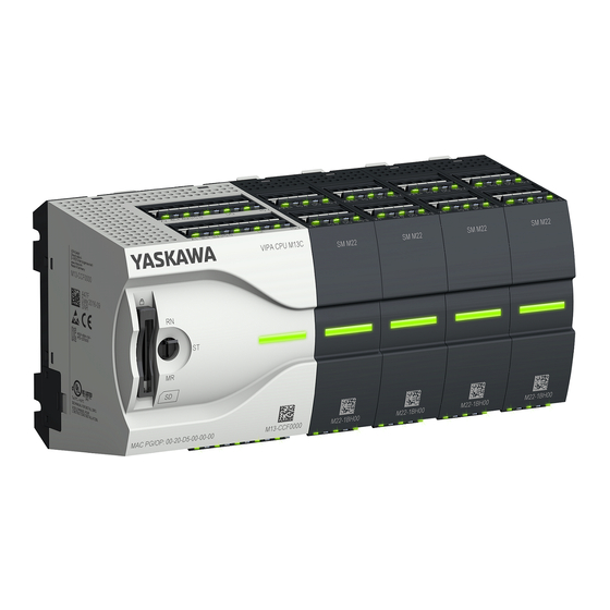
YASKAWA VIPA System MICRO M13-CCF0000 Manual (248 pages)
Brand:
YASKAWA
| Category:
Computer Hardware
| Size: 11 MB
Table of Contents
Table of Contents
3
1 General
7
Copyright © VIPA Gmbh
7
About this Manual
8
Safety Information
9
2 Basics and Mounting
10
Safety Information for Users
10
System Conception
10
Dimensions
12
Mounting
13
Mounting CPU
13
Mounting the Extension Module
16
Mounting Periphery Module
17
Wiring
18
Wiring CPU
18
Wiring Periphery Module
20
Demounting
22
Demounting CPU
22
Demounting the Extension Module
26
Demounting Periphery Module
27
Installation Guidelines
29
General Data
31
3 Hardware Description
33
Properties
33
Structure
34
System MICRO CPU M13C
34
Interfaces
35
Leds
40
Memory Management
41
Slot for Storage Media
42
Buffering Mechanisms
42
Operating Mode Switch
42
Option: Extension Module EM M09 2X Serial Interface
43
Technical Data
44
Technical Data CPU
44
Technical Data EM M09
55
4 Deployment CPU M13-CCF0000
56
Assembly
56
Start-Up Behavior
56
Addressing
56
Overview
56
Default Address Assignment of the I/O Part
56
Option: Addressing Periphery Modules
57
Hardware Configuration - CPU
58
Hardware Configuration - System MICRO Modules
60
Hardware Configuration - Ethernet PG/OP Channel
61
Setting Standard CPU Parameters
63
Parametrization Via Siemens CPU
63
Parameter CPU
63
Setting VIPA Specific CPU Parameters
66
Project Transfer
68
Transfer Via Ethernet
68
Transfer Via Memory Card
68
Option: Transfer Via MPI
69
Accessing the Web Server
70
Access Via the Ethernet PG/OP Channel
70
Structure of the Web Page
70
Web Page with Selected CPU
71
Operating Modes
73
Overview
73
Function Security
74
Overall Reset
75
Overall Reset by Means of the Operating Mode Switch
75
Overall Reset by Means of the Siemens SIMATIC Manager
76
Actions after the Overall Reset
76
Firmware Update
76
Reset to Factory Settings
78
Deployment Storage Media - VSD, VSC
79
Extended Know-How Protection
81
CMD - Auto Commands
82
Control and Monitoring of Variables with Test Functions
84
Diagnostic Entries
85
5 Deployment I/O Periphery
86
Overview
86
Address Assignment
87
Analog Input
87
Properties
87
Analog Value Representation
88
Wiring
89
Parametrization
89
Digital Input
90
Properties
90
Wiring
91
Parametrization
92
Status Indication
93
Digital Output
94
Properties
94
Wiring
94
Parametrization
95
Status Indication
95
Counting
96
Properties
96
Wiring
96
Proceeding
99
Parametrization
99
Counter Operating Modes
104
Counter - Additional Functions
111
Diagnostics and Interrupt
117
Frequency Measurement
117
Properties
117
Wiring
118
Proceeding
120
Parametrization
120
Status Indication
122
Pulse Width Modulation - PWM
123
Properties
123
Wiring
124
Proceeding
124
Parametrization
125
Status Indication
127
Diagnostic and Interrupt
128
Overview
128
Process Interrupt
128
Diagnostic Interrupt
131
6 Deployment PG/OP Communication - Productive
140
Basics - Industrial Ethernet in Automation
140
Basics - ISO/OSI Reference Model
141
Basics - Terms
142
Basics - Protocols
143
Basics - IP Address and Subnet
144
Fast Introduction
146
Hardware Configuration
146
Configure Siemens S7 Connections
147
Configure Open Communication
152
7 Option: Ptp Communication
155
Fast Introduction
155
Principle of the Data Transfer
156
Ptp Communication Via Extension Module EM M09
157
Parametrization
160
FC/SFC 216 - SER_CFG - Parametrization Ptp
160
Communication
161
FC/SFC 217 - SER_SND - Send to Ptp
161
FC/SFC 218 - SER_RCV - Receive from Ptp
161
Protocols and Procedures
161
Modbus - Function Codes
164
8 Option: Deployment PROFIBUS Communication
169
Fast Introduction
169
PROFIBUS Communication
169
PROFIBUS Communication Via Extension Module EM M09
170
Deployment as PROFIBUS DP Slave
172
PROFIBUS Installation Guidelines
174
Commissioning and Start-Up Behavior
176
9 Configuration with VIPA SPEED7 Studio
178
SPEED7 Studio - Overview
178
SPEED7 Studio - Work Environment
179
Project Tree
181
Catalog
182
SPEED7 Studio - Hardware Configuration - CPU
184
SPEED7 Studio - Hardware Configuration - Ethernet PG/OP Channel
184
SPEED7 Studio - Hardware Configuration - I/O Modules
187
Deployment I/O Periphery
188
Overview
188
Analog Input
188
Digital Input
188
Digital Output
189
Counter
189
Frequency Measurement
193
Pulse Width Modulation - PWM
195
SPEED7 Studio - Project Transfer
197
Transfer Via MPI
197
Transfer Via Ethernet
199
Transfer Via Memory Card
200
10 Configuration with TIA Portal
201
TIA Portal - Work Environment
201
General
201
Work Environment of the TIA Portal
201
TIA Portal - Hardware Configuration - CPU
202
TIA Portal - Hardware Configuration - Ethernet PG/OP Channel
205
TIA Portal - VIPA-Include Library
207
TIA Portal - Project Transfer
208
Transfer Via Ethernet
208
Transfer Via Memory Card
209
Option: Transfer Via MPI
209
Appendix
211
A System Specific Event Ids
213
B Integrated Blocks
246
Advertisement
Advertisement
Related Products
YASKAWA VIPA System MICRO
YASKAWA MOTOMAN-VA1400
YASKAWA MOTOMAN-EPX2050
YASKAWA Motoman MH1500
YASKAWA MH24
YASKAWA MPL160-J00
YASKAWA MA2010
YASKAWA MH505 SIGMA-5
YASKAWA MH95 SIGMA-5
YASKAWA MOTOMAN-MPL500
YASKAWA Categories
Controller
DC Drives
Servo Drives
Robotics
Control Unit
More YASKAWA Manuals
Login
Sign In
OR
Sign in with Facebook
Sign in with Google
Upload manual
Upload from disk
Upload from URL