Sign In
Upload
Manuals
Brands
Trane Manuals
Chiller
RTAA-70
Trane RTAA-70 Manuals
Manuals and User Guides for Trane RTAA-70. We have
1
Trane RTAA-70 manual available for free PDF download: Installation & Maintenance Manual
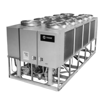
Trane RTAA-70 Installation & Maintenance Manual (179 pages)
R Series Air-Cooled Rotary Liquid Chillers
Brand:
Trane
| Category:
Chiller
| Size: 8.43 MB
Table of Contents
Table of Contents
3
General Information
5
Unit Identification - Nameplates
5
Standatd Unit Nameplate
5
Pump Package Unit Nameplate
5
Unit Inspection
6
Inspection Checklist
6
Loose Parts Inventory
6
Unit Description
7
General RTAA Mechanical Specifications
8
Model Number Coding System
9
Installation — Mechanical
10
Installation Responsibilities
10
Storage
10
Location Requirements
10
Foundation
11
RTAA Rigging and Lifting Weights – Packaged Unit
12
RTAA Rigging and Lifting Weights – Remote Evaporator
13
RTAA Rigging and Lifting Weights –Pump Package Aluminum Fins
14
RTAA Rigging and Lifting Weights –Pump Package Copper Fins
15
Clearances
16
Additional Location Requirements for Remote Evaporator Only
16
Rigging
16
Lifting Procedure
17
Dimensions and Clearances for RTAA Packaged Unit 70 – 125 Tons
18
Remote Evaporator Dimensions, RTAA 70 – 125 Tons
20
Remote Evaporator Dimensions, RTAA 110 – 125 Tons
21
Unit Isolation
23
Direct Mounting
23
Neoprene Isolators
23
Unit Leveling
23
Water Piping
23
Isolator Placement for Typical RTAA Packaged Unit 70 – 125 Tons
24
Isolator Placement for RTAA with Remote Evaporator
25
Evaporator Water Piping
26
Evaporator Piping Components
27
Entering Chilled Water Piping
27
Leaving Chilled Water Piping Air Vents (to Bleed Air from System)
27
Suggested Piping for Typical RTAA Evaporator
27
Evaporator Drain
28
Chilled Water Flow Switch
28
Water Treatment
29
Customer Note
29
Water Pressure Gauges
29
RTAA Evaporator Water Pressure Drop
29
Water Pressure Relief Valves
30
Freeze Protection
30
System Configuration and Interconnecting Refrigerant Piping
31
Installation - Remote Evaporator
31
Remote Evaporator Installation
32
Refrigerant Circuit Identification
34
RTAA Circuit Capacities (Nominal Tons)
35
Equivalent Lengths of Non-Ferrous Valves and Fittings (Feet)
35
Liquid Line Sizes
36
Line Sizing
38
Liquid Line Sizing Steps
38
Additional Suction Accumulator Line
39
Example Liquid Line Sizing
39
Suction Line Sizing Steps
40
Liquid Line Sizing Example
40
Example Suction Line Sizing
41
Suction Accumulator Sizing
42
Top View
43
Side View
43
Piping Installation Procedures
44
Refrigerant Sensors
44
Refrigerant Sensor Mounting and Wiring
45
Leak Test and Evacuation
46
Refrigerant and Additional Oil Charge
46
Refrigerant Charge Determination
46
System Refrigerant Charge
46
Oil Charge Determination
47
Example: Refrigerant Charge Computation
47
Field-Installed Piping Charge
47
Relief Valve Venting
47
General Recommendations
49
Installation - Electrical
49
Electrical Data
50
Electrical Data - Pump Package Option
51
Installer-Supplied Components
51
Power Supply Wiring
52
Control Power Supply
52
Water Pump Power Supply
52
Interlock Wiring
52
Installation — Electrical
53
Typical RTAA Chiller Interlock
53
Alarm/Running/Maximum Capacity Outputs
54
Alarm/Running/Maximum Capacity Relay Output Configurations
54
Alarm/Running/Maximum Capacity Indicator Wiring
54
Alarm/Running/Maximum Capacity Contact Outputs
55
Alarm/Running/Maximum Capacity Menu Settings
55
Low Voltage Wiring
56
Emergency Stop (Normal Trip)
56
External Circuit Lockout
56
Ice Making Option
56
External Chilled Water Setpoint (CWS)
57
Resistor and Potentiometer
57
Input Values Vs. External Chilled Water Setpoint
58
External Current Limit Setpoint (CLS)
59
Input Values Vs. External Current Limit Setpoint
60
2-10 VDC Voltage Source Input
60
4-20 Ma Current Source Input
60
Optional Bidirectional Communications Link (BCL)
60
Communication Link Connection Procedure
61
Lontalk Communication Interface (LCI-C)
61
Remote Clear Language Display Installation Procedure
62
Remote CLD Mounting
62
Remote CLD Panel Wiring
63
Remote CLD Panel Mounting Holes and Electrical Access Knockouts
63
ICS Address Setting
64
Multiple Unit Operation
64
Refrigeration (Cooling) Cycle
66
Cycle Description
66
Operating Principles
66
RTAA Refrigeration System and Control Components
67
Compressor Description
67
Compressor Motor
67
Compressor Rotors
68
RTAA Refrigerant and Oil Diagram
68
Compressor Loading Sequence
69
Oil System Operation
69
Oil Separator
69
Compressor Bearing Oil Supply
70
Compressor Rotor Oil Supply
70
Female Unloader Valve
70
Oil Filter
70
Fan State at Circuit Startup
71
Controls Interface
72
Clear Language Display Keypad Overview
72
Select Report Group
73
Operator Interface Adaptive Control
73
Select Settings Group
74
Passwords
74
Select Report Group and Select Settings Group Flowcharts
74
Auto/Stop Keys
75
Power up
75
Diagnostics
93
Operational Features
94
Entering Evaporator Water Temperature
94
Current Limit Setpoint
94
Low Ambient Lockout
94
Current Overload Protection
95
Leaving Chilled Water Temperature Control
95
Chilled Water Reset (CWR)
95
Leaving Water Temperature Cutout
97
Low Refrigerant Temperature Cutout
97
Leaving Fluid Temperature Setpoints
98
Low Ambient Temperature Start
98
Low Refrigerant Temperature Cutout and Low Pressure Cutout Retry
99
Balanced Compressor Starts and Hours
99
Phase Imbalance Protection
99
Reverse Rotation Protection
100
Oil Failure Protection
100
DIP Switch Settings
100
IPC Address
100
Compressor Overload DIP Switch Settings
101
Mechanical Control Settings
102
Remote CLD Operation
102
Communication Failure
102
Pre-Start Checkout
103
Unit Voltage Power Supply
105
Unit Voltage Imbalance
105
Unit Voltage Phasing
106
Water System Flow Rates
107
Water System Pressure Drop
107
Clear Language Display Set-Up
107
Start-Up Procedures
108
Unit Sequence of Operation
110
System Superheat
111
System Subcooling
111
Temporary Shutdown and Restart
112
Unit Shutdown Procedures
112
Extended Shutdown Procedure
112
System Restart after Extended Shutdown
113
Periodic Maintenance
115
Weekly Maintenance
115
Monthly Maintenance
115
Annual Maintenance
116
RTAA Operator's Log
117
RTAA Log
118
Coil Cleaning
119
Chemical Cleaning Configuration
119
Maintenance
119
Chemically Cleaning the Evaporator
120
Oil Separator Level Check
120
Water Treatment
120
Oil Filter Change
121
System Oil Level Specifications
121
35 & 40 Ton Compressor Oil Filter Replacement Chart
124
50 & 60 Ton Compressor Oil Filter Replacement Chart
124
Refrigerant Charging and Recovery
125
Low Side Repairs
125
High Side Repair
126
Adding Refrigerant
126
Diagnostic Types (and Action)
127
Diagnostic Codes
127
Pump Package
135
Temporary Storage
135
Piping
135
Water Storage
135
Pre-Start Review and Inspection
135
Control Panel Features and Options
136
Connection Power
136
Pump Checkout Procedure
137
Control Panel Checkout
137
System Start-Up
138
C - Pump Curves before Impeller Trim
139
D - Pump Curves before Impeller Trim
139
E - Pump Curves before Impeller Trim
140
F - Pump Curves before Impeller Trim
140
Planned Shutdown
141
G - Pump Curves before Impeller Trim
141
Maintenance
141
Pump Package Troubleshooting
142
Pump Package Piping Schematic
143
Unit Wiring
145
Unit Electrical Data
145
Advertisement
Advertisement
Related Products
Trane RTAA-80
Trane RTAA-90
Trane RTAA-110
Trane RTAA-170
Trane RTAA-270
Trane RTAA-400
Trane RTAA-200
Trane RTAA-300
Trane RTAA-130
Trane RTAA-240
Trane Categories
Air Conditioner
Heat Pump
Chiller
Air Handlers
Furnace
More Trane Manuals
Login
Sign In
OR
Sign in with Facebook
Sign in with Google
Upload manual
Upload from disk
Upload from URL