Sign In
Upload
Manuals
Brands
Texas Instruments Manuals
Motherboard
DLPLCRC910EVM
Texas Instruments DLPLCRC910EVM Manuals
Manuals and User Guides for Texas Instruments DLPLCRC910EVM. We have
2
Texas Instruments DLPLCRC910EVM manuals available for free PDF download: User Manual
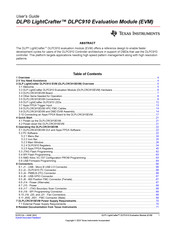
Texas Instruments DLPLCRC910EVM User Manual (79 pages)
Brand:
Texas Instruments
| Category:
Motherboard
| Size: 21.15 MB
Table of Contents
Table of Contents
1
Overview
4
If You Need Assistance
4
Figure 1-1. DLP Lightcrafter DLPC910 Evaluation Module
4
DLP Lightcrafter DLPC910 EVM (DLPLCRC910EVM) Overview
5
Welcome
5
DLP Lightcrafter DLPC910 Evaluation Module (DLPLCRC910EVM) Hardware
6
Figure 3-1. DLPLCRC910EVM Hardware Components
6
DLPLCRC910EVM Board
7
Figure 3-2. DLP Lightcrafter DLPC910 EVM Block
7
Other Items Needed for Operation
8
DLPLCRC910EVM Connections
8
Figure 3-3. DLPLCRC910EVM Connectors
8
Table 3-1. DLPLCRC910EVM Connector Reference
9
DLP Lightcrafter DLPC910 Leds
12
Figure 3-4. DLP Lightcrafter DLPC910 EVM Leds
12
Figure 3-5. DLP Lightcrafter DLPC910 EVM Leds (Top View - Lower Left)
12
Table 3-2. DLP Lightcrafter DLPC910 EVM LED Reference
12
Apps FPGA Trigger Input
13
Figure 3-6. J3 Apps FPGA Test Point Header
13
Figure 3-7. VC-707 SW5
13
DLPLCRC910EVM HPC FMC Cables
14
DLPLCRC910EVM and DMD EVM Assembly
14
Figure 3-8. HPC FMC Cable
14
Figure 3-9. DLPLCRC910EVM Female HPC FMC
14
Figure 3-10. DLPLCR65FLQEVM Male HPC FMC
14
Figure 3-11. DLPLCR90XEVM Male HPC FMC
14
Figure 3-12. Samtec 300 MM HPC FMC Extension Cable
15
Figure 3-13. Assembled DLPLCRC910EVM with DLPLCR65FLQEVM (Without Cable)
15
Figure 3-14. Assembled DLPLCRC910EVM with DLPLCR90XEVM or DLPLCR90XUVEVM (Without Cable)
15
Figure 3-15. Assembled DLPLCRC910EVM with DLPLCR65FLQEVM (with Cable)
16
Figure 3-16. Assembled DLPLCRC910EVM with DLPLCR90XEVM or DLPLCR90XUVEVM (with Cable)
16
Connecting an Apps FPGA Board to the DLPLCRC910EVM
17
Figure 3-17. AMD VC-707 Board Dip Switch Settings
17
Figure 3-18. DLPLCRC910EVM Male HPC FMC Connectors (for Apps FPGA Board)
17
Figure 3-19. AMD Xilinx VC-707 Female HPC FMC Cable Connectors
17
Figure 3-20. Assembled DLPLCRC910EVM with AMD Xilinx VC-707 Board (Without Cables)
18
Figure 3-21. Fully Assembled DLPLCRC910EVM - AMD Xilinx VC-707 - DLPLCR65FLQEVM (Without Cables)
18
Figure 3-22. Fully Assembled DLPLCRC910EVM - AMD Xilinx VC-707 - DLPLCR90XEVM or DLPLCR90XUVEVM
18
Figure 3-23. Assembled DLPLCRC910EVM with AMD Xilinx VC-707 Board (with Cables)
19
Figure 3-24. Fully Assembled DLPLCRC910EVM - AMD Xilinx VC-707 - DLPLCR65FLQEVM (with Cables)
20
Figure 3-25. Fully Assembled DLPLCRC910EVM - AMD Xilinx VC-707 - DLPLCR90XEVM or DLPLCR90XUVEVM
20
Quick Start
21
Power-Up the DLPLCRC910EVM
21
Power-Down the DLPLCRC910EVM
21
Operating the DLPLCRC910EVM
22
DLPLCRC910EVM GUI and Apps FPGA Software
22
PC Software
22
Figure 5-1. DLPLCRC910EVM GUI
22
Figure 5-2. High DPI Settings
23
Menu Bar
24
Figure 5-3. File Menu
24
Figure 5-4. Control Menu
24
Figure 5-5. Help Menu
24
Icon Bar
25
Figure 5-6. about Box
25
Figure 5-7. Icon Bar
25
Main Window
26
Figure 5-8. Load Tab
26
Figure 5-9. Reset Tab
28
Figure 5-10. Clear Tab
29
Figure 5-11. Float Tab
30
Figure 5-12. Control Tab
31
Figure 5-13. Script Sub-Window
33
DLPC910 Registers
34
Figure 5-14. Status Sub-Window
34
Figure 5-15. Status/Control Tab
34
Figure 5-16. Status Items
35
Figure 5-17. DMD Control Section
36
Figure 5-18. Design Items
37
Figure 5-19. DLPC910 Register List Tab
38
Table 5-1. DESTOP_INTERRUPT_CLEAR
39
Table 5-2. DESTOP_INTERRUPT_SET
39
Table 5-3. DESTOP_INTERRUPT_ENABLE
39
Table 5-4. MAIN_STATUS Definition
40
Table 5-5. DESTOP_CAL Definition
41
Table 5-6. DESTOP_DMD_ID_REG
41
Table 5-7. DESTOP_CATBITS_REG
41
Table 5-8. DESTOP_910VERSION_REG Definition
41
Table 5-9. DESTOP_RESET_REG
42
Table 5-10. DESTOP_INFIFO_STATUS
42
Table 5-11. DESTOP_BUS_SWAP
42
Table 5-12. DESTOP_DMDCTRL
43
Table 5-13. DESTOP_BIT_FLIP Definition
43
Figure 5-20. DLPC910 I 2 C Address Settings Tab
44
Apps FPGA Registers
45
Figure 5-21. Status/Control Tab
45
Figure 5-22. Status Items
46
Figure 5-23. PBC Control Section
47
Figure 5-24. Row/Block Operations
48
Figure 5-25. Test Pattern Items
50
Figure 5-26. Apps Registers Tab
52
Table 5-14. APPS_INTERRUPT_CLEAR
53
Table 5-15. APPS_INTERRUPT_SET
53
Table 5-16. APPS_INTERRUPT_ENABLE
54
Table 5-17. MAIN_STATUS Definition
54
Table 5-18. APPS_CNTRL Definition
55
Table 5-19. APPSTOP_PATTERNSEL Definition
56
Table 5-20. APPSTOP_TEST_ROWADDR Definition
57
Table 5-21. APPSTOP_LOADER_RESET_TYPE Definition
57
Table 5-22. DMD_TYPEREG
57
Table 5-23. APPS_BUFFER_WSTART Definition
58
Table 5-24. APPS_FIFO_BURST Definition
58
Table 5-25. APPS_ROW_CTRL Definition
58
Table 5-26. APPS_BLK_CTRL Definition
58
Table 5-27. APPS_ROW_LOADER
58
Table 5-28. APPS_LOAD_TRIG_INTERVAL
59
Table 5-29. APPS_EXPOSE_TIME Definition
59
Table 5-30. APPS_LOADER_CTRL Definition
59
Table 5-31. APPS_DMD_PARK
60
Table 5-32. APPS_EXT_RST_EVT Definition
60
Table 5-33. APPS_BUILD_DATE
61
Table 5-34. APPS_VERSION Definition
61
Table 5-35. APPS_FIXED_ID Definition
61
Table 5-36. APPS_GPIF_TEST
61
JTAG Flash Programming
62
SPI Flash Programming
63
AMD Xilinx VC-707 Configuration PROM Programming
63
Figure 5-27. VC-707 USB-JTAG Port
63
USB Firmware Programming
64
Figure 5-28. USB Control Center Window
64
Figure 5-29. FX2/64KB EEPROM
64
Figure 5-30. Select File to Download Dialog
64
Connectors
66
J1 - USB - Micro B USB 2.0 Connector
66
J2 - Dlpc910 I
66
Connector
66
J4 - Pmbus
66
Table 6-1. Micro B USB 2.0 Receptacle Connector Pins
66
Table 6-2. I 2 C Connector Pins
66
Table 6-3. PMBUS (I 2 C) Connector Pins
66
J6 - USB GPIO Connector
67
J8 - 400 Position FMC Connector (Female)
67
J14 - Power (Alternate)
67
Table 6-4. USB GPIO Connector Pins
67
Table 6-5. Alternate Power Connector Pins
67
J15 - Power
68
J17 - JTAG Boundary Scan Connector
68
Table 6-6. Power Connector Pins
68
Table 6-7. JTAG Boundary Scan Connector Pins
68
J18 - SPI Programming Connector
69
J19, J20, and J21 - Fan Connectors
69
J500, J501 - FMC Connector (Male)
69
Table 6-8. SPI Programming Connector Pins
69
Table 6-9. Fan Connector Pins
69
DLPLCRC910EVM Power Supply Requirements
70
External Power Supply Requirements
70
Related Documentation from Texas Instruments
71
Dlpu124 - June 2023
71
Abbreviations and Acronyms
71
Caution Labels
73
Advertisement
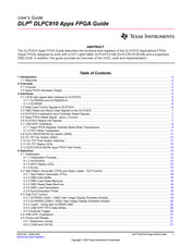
Texas Instruments DLPLCRC910EVM User Manual (42 pages)
Brand:
Texas Instruments
| Category:
Computer Hardware
| Size: 1.94 MB
Table of Contents
Table of Contents
1
Introduction
4
Welcome
4
Overview
5
Purpose
5
Apps FPGA Hardware Target
5
Figure 2-1. Apps FPGA Hardware Target
5
Interfaces
6
LVDS High Speed Data Interface to DLPC910
6
DLP9000X and DLP9000XUV
6
Dlp6500
6
Data Load Control Signals to DLPC910
6
Table 3-1. Apps FPGA - LVDS Data Interface Output Signal Names
6
Table 3-2. Data Load Control Signals
6
DMD Reset and Block Clear Signals to the DLPC910
7
DLPC910 Initialization and Controller Reset Signals
7
DLPC910 Status-Info Signals
7
Table 3-3. Reset and Block Clear Signals
7
Table 3-4. DLPC910 Initialization and Controller Reset Signals
7
Table 3-5. DLPC910 Status-Info Signals
7
USB GPIF (Interface)
8
Apps FPGA Register Address Read-Write Transactions
8
Table 3-6. USB GPIF Interface Signals
8
Table 3-7. USB GPIF Transaction Type Definition
8
Figure 3-1. Register Address Transaction Timing Diagram
9
Figure 3-2. Register Data Write Transaction Timing Diagram
9
Table 3-8. Register Address Transaction Example
9
Figure 3-3. Register Data Read Transaction Timing Diagram
10
Table 3-9. Register Data Write Transaction Example
10
Table 3-10. Register Data Read Transaction Example
10
FIFO Write Transaction
11
DLPLCRC910EVM Dip Switch (SW2)
11
Figure 3-4. FIFO Write Transaction Timing Diagram
11
Table 3-11. DLPLCRC910EVM Dip Switch (SW2)
11
VC-707 Dip Switch (SW2)
12
VC-707 Push Button Switches
12
VC-707 Status Leds
12
Table 3-12. VC-707 Dip Switch (SW2)
12
Table 3-13. VC-707 Push Button Switches
12
Table 3-14. VC-707 Status Leds
12
DLPLCRC910EVM Apps FPGA Test Points
13
Table 3-15. DLPLCRC910EVM Apps FPGA Test Points
13
Operation
14
Initialization
14
Initialization Prompts
14
Figure 4-1. Apps FPGA Functional Block Diagram
14
Init Routine
15
GPIO Status Leds
15
Errors
15
Test Pattern Generator (TPG) and Apps Loader - DLP Control
15
Figure 4-2. Apps Loader Data Flow
15
Test Pattern Generator (TPG)
16
DMD Data Buffer
16
DMD Load State Machine
16
Figure 4-3. DMD Load State Machine
17
DMD Reset State Machine
18
DMD Load Parameters
18
Synchronization Pulse
18
User DLP Control
18
DLP6500 (1920 X 1080) User Image Display Example (Global)
19
DLP9000X (2560 X 1600) User Image Display Example (Global)
20
Load4 - Using with DLP6500 DMD
20
USB GPIF FIFO Data Writes
20
External Trigger
20
USB GPIF (Operation)
21
Clocks and Resets
21
Reference Clocks
21
Clk50 and Clk100
21
DLP Clocks
21
USB GPIF Clock
21
Logic Resets
21
Clock Domain Crossings (CDC)
22
Switch Debounce
22
USB GPIF Registers
23
Register Definitions
23
Status (0X000C)
23
Data Loading Control (0X0010)
24
Test Pattern Control (0X0014)
24
Test Row Address (0X0018) - [Unused]
25
Loader Reset Type (0X001C)
25
Type and Version (0X0020)
25
User Image Buffer Write Settings (0X0024)
25
USB GPIF FIFO Read Burst Size (0X0028) - [Obsolete]
26
User Row Command Register (0X002C)
26
User Block Command Register (0X0030)
26
Loader Row Control (0X0034)
27
Loader Load Interval (0X0038)
27
Loader Expose Time (0X003C)
27
Address Write (0X003F) - [Unused]
27
Loader Control (0X0040)
27
Park [PWR_FLOAT] (0X0044)
28
External Trigger Status (0X0048)
28
FPGA Build Date (0X0080)
28
Major-Minor Revision (0X0084)
28
Fixed Value FPGA Identifier (0X0088)
28
Test Register (0X008C)
28
FPGA Configuration
29
Apps FPGA Source Files and Compilation
30
Design Tools
30
Source Files
30
Primary VHDL and IP Modules
30
Figure 7-1. Source Files
30
Modules with Multiple Instantiations
31
VHDL Packages
31
Vivado Constraints
31
Memory IP Initialization Files
31
Building the Apps FPGA Code
31
Source Code
31
Creating the Vivado Project
32
Compiling the Design
32
Simulation
32
Figure 7-2. Test Benches
33
Figure 7-3. Settings Dialog
33
Figure 7-4. Vivado Waveform Window
34
Related Documentation from Texas Instruments
35
Appendix
35
Abbreviations and Acronyms
35
Information about Cautions and Warnings
36
Advertisement
Related Products
Texas Instruments DLPLCRDC4422EVM
Texas Instruments DLPLCR4500EVM
Texas Instruments DLPLCRC964
Texas Instruments DLP5530PGUQ1EVM
Texas Instruments DLP5534PROJQ1EVM
Texas Instruments DLP3021LEQ1EVM
Texas Instruments DLP5532HBQ1EVM
Texas Instruments DLP4710EVM-LC
Texas Instruments DLPC4430
Texas Instruments DLPC900EVM
Texas Instruments Categories
Motherboard
Control Unit
Microcontrollers
Computer Hardware
Calculator
More Texas Instruments Manuals
Login
Sign In
OR
Sign in with Facebook
Sign in with Google
Upload manual
Upload from disk
Upload from URL