Sign In
Upload
Manuals
Brands
Terex Manuals
Accessories
Genie Lift Guard S-60
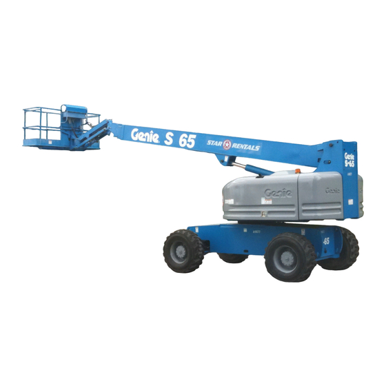
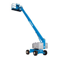
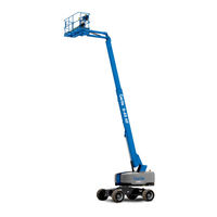
Terex Genie Lift Guard S-60 Manuals
Manuals and User Guides for Terex Genie Lift Guard S-60. We have
5
Terex Genie Lift Guard S-60 manuals available for free PDF download: Service Manual, Maintenance Manual, Operator's Manual Supplement
Terex Genie Lift Guard S-60 Service Manual (475 pages)
Brand:
Terex
| Category:
Lifting Systems
| Size: 39.2 MB
Table of Contents
Find a Manual for this Model
2
Revision History
3
Serial Number Legend
5
Safety Rules
6
Table of Contents
8
Specifications
23
Machine Specifications
23
Performance Specifications
24
Hydraulic Specification
25
Hydraulic Component Specifications
27
Ford MSG-425 EFI Engine Specifications
29
Deutz D2011 L03I Engine Specifications
30
Deutz Td2011L04I Engine Specifications
32
Deutz D 2.9 L4 Engine Specifications
34
Perkins 404D-22 Engine Specifications
36
Perkins 404F-22 Engine Specifications
37
Machine Torque Specifications
39
Hydraulic Hose and Fitting Torque Specifications
40
Torque Procedure
41
Scheduled Maintenance Procedures
43
Introduction
43
Pre-Delivery Preparation Report
46
Maintenance Inspection Report
47
Checklist a Procedures
49
Inspect the Manuals and Decals
49
Perform Pre-Operation Inspection
50
Perform Function Tests
50
Perform Engine Maintenance - Ford Models
51
Perform Engine Maintenance - Deutz Models
51
Perform Engine Maintenance -Perkins Models
52
Check the High Pressure Hydraulic Filter Condition Indicator
52
Test the Oscillate Axle
53
Inspect the Track Components, S-60 TRAX and S-65 TRAX
53
Perform 30 Day Service
54
Check the Track Tension and Fastener Torque
54
TRAX and S-65 TRAX
54
Perform Engine Maintenance - Ford Models
56
Inspect the Fuel Filter/ Water Separator - Perkins Models
57
Check and Adjust the Engine RPM - Perkins 404D-22 Models
58
Grease the Turntable Rotation Bearing and Rotate Gear
59
Replace the Drive Hub Oil
59
Perform Engine Maintenance - Ford Models
61
Checklist B Procedures
62
Inspect the Battery
62
Inspect the Electrical Wiring
63
B-3 Check the Exhaust System
64
Perform Engine Maintenance - Perkins Models
65
Check the Oil Cooler and Cooling Fins - Deutz D2011 L03I Models
65
Inspect the Tires, Wheels and Lug Nut Torque
66
HC, S60X and S-60XC
66
Confirm the Proper Brake Configuration
67
Check the Drive Hub Oil Level and Fastener Torque
67
Check and Adjust the Engine RPM
69
Test the Ground Control Override
70
Check the Oscillate Directional Valve Linkage
71
Test the Platform Self-Leveling
71
Test the Engine Idle Select
72
Test the Drive Brakes
74
Test the Drive Speed - Stowed Position
74
Test the Drive Speed - Raised or Extended Position
75
Test the Alarm Package (if Equipped)
76
Perform Hydraulic Oil Analysis
77
Inspect the Fuel and Hydraulic Tank Cap Venting Systems
77
Inspect the Boom Extend/Retract Cables
78
Test the Emergency Power System
80
Perform Engine Maintenance - Ford Models
81
Checklist C Procedures
82
Perform Engine Maintenance - Perkins Models
82
Grease the Platform Overload Mechanism (if Equipped
83
S-65, S-60 TRAX and S-65 TRAX
83
Test the Platform Overload System (if Equipped)
84
Test the Platform Load Sense System, S-60 HC
86
Replace the Fuel Filter/Water Separator - Perkins Models
88
Check the Safety Envelope Limit Switches and Angle Sensor
90
S-60X and S-60XC
90
Perform Engine Maintenance - Ford Models
92
Checklist D Procedures
93
Check the Boom Wear Pads
93
Check the Turntable Rotation Bearing Bolts
94
Inspect for Turntable Bearing Wear
95
Replace the Drive Hub Oil
96
Check the Free-Wheel Configuration
98
Replace the Hydraulic Filters
100
Perform Engine Maintenance - Deutz Models
101
Perform Engine Maintenance - Perkins Models
102
Checklist E Procedures
103
Test or Replace the Hydraulic Oil
103
Perform Engine Maintenance - Perkins Models
104
Perform Engine Maintenance - Deutz Models
105
Perform Engine Maintenance - Perkins 404D-22 Models
105
Perform Engine Maintenance - Perkins 404F-22 Models
106
Perform Engine Maintenance - Perkins Models
106
Perform Engine Maintenance - Deutz D 2.9 L4 Models
107
Perform Engine Maintenance - Perkins 404D-22 Models
107
Perform Engine Maintenance - Perkins Models
108
Replace the Boom Extend and Retract Cables
108
Repair Procedures
109
Platform Controls
111
ALC-500 Circuit Board
111
Joysticks
112
How to Adjust the Joystick Threshold Setting
113
How to Adjust the Joystick Max-Out Setting
114
How to Adjust the Joystick Ramp Rate Setting
115
How to Calibrate the Boom Angle Sensor
116
Platform Components
118
Platform Leveling Slave Cylinder
118
Platform Rotator
119
Platform Overload System
122
TRAX and S-65 TRAX (if Equipped)
122
Platform Load Sense System, S-60 HC
124
Platform Load Sense
124
Jib Boom Components
128
Jib Boom
128
Jib Boom Lift Cylinder
129
Boom Components
130
Cable Track
130
How to Remove the Cable Track
130
S-60, S-60X, S-60XC, S-60 HC and S-60 TRAX
130
How to Remove the Cable Track, S-65 and S-65 TRAX
131
How to Repair the Cable Track
133
Boom
135
Boom Lift Cylinder
138
Boom Extension Cylinder
139
Boom Extend/Retract Cables
142
Platform Leveling Master Cylinder
145
Primary Boom Angle Sensor, S-60X and S-60XC
146
Engines
148
RPM Adjustment - Ford and Deutz Models
148
RPM Adjustment - Perkins 404D-22 Models
148
Flex Plate - Removal
148
How to Install a Type "A" Flex Plate
150
How to Install a Type "B" Flex Plate
151
How to Install the Pump and Bell Housing Assembly
152
Ford MSG-425 Engine Fault Codes
153
Engine Fault Codes - Deutz D 2.9 L4 and Perkins 404F-22 Models
154
Hydraulic Pump
155
Lift/Steer Pump
155
Drive Pump
156
Manifolds
158
Function Manifold Components (to Serial Number 26514)
158
Function Manifold Components (from Serial Number 26515)
162
Valve Adjustments - Function Manifold
166
Jib Boom / Platform Rotate Manifold Components
167
Brake/Two-Speed Manifold Components
168
Turntable Rotation Manifold Components
169
Oscillate Directional Valve Components
170
How to Set up the Oscillate Directional Valve
171
Valve Adjustments - Oscillate Relief Valve
172
Drive Oil Diverter Manifold Components (Welder Option)
173
Traction Manifold Components, 2WD
174
Valve Adjustments, 2WD Traction Manifold
175
Traction Manifold Components, 4WD
176
Valve Adjustments, 4WD Traction Manifold
178
Hydraulic Generator Manifold Components, 3Kw
179
Valve Coils
180
How to Test a Coil Diode
181
Turntable Rotation Components
182
Turntable Rotation Assembly
182
How to Adjust the Turntable Rotation Gear Backlash
183
Axle Components
185
Oscillating Axle Cylinders
185
Track Components
186
How to Replace a Track
186
Fault Codes
191
Control System Fault Codes
192
How to Retrieve Control System Fault Codes
192
Control System Fault Codes
193
Fault Code Display - Deutz and Perkins Models
197
How to Retrieve Active Engine Fault Codes Deutz D 2.9 L4 and Perkins 404F-22 Models
197
Deutz D 2.9 L4 and Perkins 404F-22 Models
199
Soft Key Functions and Icons - Deutz D 2.9 L4 and Perkins 404F-22 Models
199
Main Menu Structure - Deutz D 2.9 L4 Models
200
Main Menu Structure - Perkins 404F-22 Models
201
Deutz D 2.9 L4 Engine Fault Codes
202
Perkins 404F-22 Engine Fault Codes
213
Ford MSG-425 Engine Fault Codes
215
Ford MSG-425 Engine Fault Codes
216
Load Sense System Fault Codes
221
Platform Load Sense System, S-60 HC
221
Electrical Symbol Legend
230
Hydraulic Symbols Legend
231
Limit Switch Location Legend
232
Ford Engine Relay Layout
233
Engine Relay Layout - Deutz D 2.9 L4 and Perkins 404F-22
234
Ford MSG-425 EFI Engine Wire Harness
236
Deutz D 2.9 L4 Engine Wire Harness
237
Perkins 404F-22 Engine Wire Harness
239
Electrical Schematic, Options Deutz D2011L03I, Td2011L04I and Perkins 404D-22
241
Electrical Schematic, Options - Deutz D 2.9 L4
243
Electrical Schematic, Options - Perkins 404F-22
245
Wiring Diagram, 3Kw Hydraulic Generator
247
Wiring Diagram, 12Kw Hydraulic Generator - Welder Option
249
Electrical Schematic, 12Kw Hydraulic Generator - Welder Option
251
Hydraulic Schematic, 12Kw Hydraulic Generator - Welder Option
253
Hydraulic Schematic, 2WD Models
255
Hydraulic Schematic, 4WD Models
257
Electrical Schematic, Ford MSG-425 EFI Models (ANSI • CSA)
259
Ground Control Box Terminal Strip Wiring Diagram, Ford MSG-425 EFI Models (ANSI • CSA)
263
Ground Control Box Switch Panel Wiring Diagram, Ford MSG-425 EFI Models (ANSI • CSA)
266
Platform Control Box Wiring Diagram, Ford MSG-425 EFI Models (ANSI • CSA)
267
Platform Control Box Switch Panel Wiring Diagram, Ford MSG-425 EFI Models (ANSI • CSA)
270
Electrical Schematic, Deutz D2011L03I Models (ANSI • CSA)
271
Electrical Schematic, Deutz Td2011L04I Models (ANSI • CSA)
275
Ground Control Box Terminal Strip Wiring Diagram, Deutz D2011L03I • Td2011L04I Models (ANSI • CSA)
279
Ground Control Box Switch Panel Wiring Diagram, Deutz D2011L03I • Td2011L04I Models (ANSI • CSA)
281
Platform Control Box Wiring Diagram, Deutz D2011L03I • Td2011L04I Models (ANSI • CSA)
283
Platform Control Box Switch Panel Wiring Diagram, Deutz D2011L03I • Td2011L04I Models (ANSI • CSA)
286
Electrical Schematic, Deutz D 2.9 L4 Models (ANSI • CSA)
287
Ground Control Box Terminal Strip Wiring Diagram, Deutz D 2.9 L4 Models (ANSI • CSA)
291
Ground Control Box Switch Panel Wiring Diagram, Deutz D 2.9 L4 Models (ANSI • CSA)
294
Platform Control Box Wiring Diagram, Deutz D 2.9 L4 Models (ANSI • CSA)
295
Platform Control Box Switch Panel Wiring Diagram, Deutz D 2.9 L4 Models (ANSI • CSA)
298
Electrical Schematic, Perkins 404D-22 Models (ANSI • CSA)
299
Ground Control Box Terminal Strip Wiring Diagram, Perkins 404D-22 Models (ANSI • CSA)
303
Ground Control Box Switch Panel Wiring Diagram, Perkins 404D-22 Models (ANSI • CSA)
306
Platform Control Box Wiring Diagram, Perkins 404D-22 Models (ANSI • CSA)
307
Platform Control Box Switch Panel Wiring Diagram, Perkins 404D-22 Models (ANSI • CSA)
310
Electrical Schematic, Perkins 404F-22 Models (ANSI • CSA)
311
Ground Control Box Terminal Strip Wiring Diagram, Perkins 404F-22 Models (ANSI • CSA)
315
Ground Control Box Switch Panel Wiring Diagram, Perkins 404F-22 Models (ANSI • CSA)
318
Platform Control Box Wiring Diagram, Perkins 404F-22 Models (ANSI • CSA)
319
Platform Control Box Switch Panel Wiring Diagram, Perkins 404F-22 Models (ANSI • CSA)
322
Electrical Schematic, S-60X • S-60XC Ford MSG-425 EFI Models (ANSI • CSA)
323
Ground Control Box Terminal Strip Wiring Diagram, S-60X • S-60XC Ford MSG-425 EFI Models (ANSI • CSA)
327
Ground Control Box Terminal Strip Wiring Diagram, S-60X • S-60XC Ford MSG-425 EFI Models (ANSI • CSA)
328
Platform Control Box Wiring Diagram, S-60X • S-60XC Ford MSG-425 EFI Models (ANSI • CSA)
331
Platform Control Box Switch Panel Wiring Diagram, S-60X • S-60XC Ford MSG-425 EFI Models (ANSI • CSA)
334
Electrical Schematic, S-60X • S-60XC
338
Deutz D2011L03I Models (ANSI • CSA)
338
Electrical Schematic, S-60X • S-60XC
339
Deutz Td2011L04I Models (ANSI • CSA)
339
Ground Control Box Terminal Strip Wiring Diagram
343
Deutz D2011L03I • Td2011L04I Models (ANSI • CSA)
343
Ground Control Box Switch Panel Wiring Diagram, S-60X • S-60XC Deutz D2011L03I • Td2011L04I Models (ANSI • CSA)
346
Platform Control Box Wiring Diagram, S-60X • S-60XC Deutz D2011L03I • Td2011L04I Models (ANSI • CSA)
347
Platform Control Box Switch Panel Wiring Diagram, S-60X • S-60XC Deutz D2011L03I • Td2011L04I Models (ANSI • CSA)
350
Electrical Schematic, S-60X • S-60XC Deutz D 2.9 L4 Models (ANSI • CSA)
351
Ground Control Box Terminal Strip Wiring Diagram, S-60X • S-60XC Deutz D 2.9 L4 Models (ANSI • CSA)
355
Ground Control Box Switch Panel Wiring Diagram,S-60X • S-60XC, Deutz D 2.9 L4 (ANSI • CSA)
358
Platform Control Box Wiring Diagram, S-60X • S-60XC Deutz D 2.9 L4 Models (ANSI • CSA)
359
Platform Control Box Switch Panel Wiring Diagram, S-60X • S-60XC Deutz D 2.9 L4 Models (ANSI • CSA)
362
Electrical Schematic, S-60X • S-60XC Perkins 404D-22 Models (ANSI • CSA)
363
Ground Control Box Terminal Strip Wiring Diagram, S-60X • S-60XC, Perkins 404D-22 Models (ANSI • CSA)
367
Ground Control Box Switch Panel Wiring Diagram, S-60X • S-60XC, Perkins 404D-22 Models (ANSI • CSA)
370
Platform Control Box Wiring Diagram, S-60X • S-60XC, Perkins 404D-22 Models (ANSI • CSA)
371
Platform Control Box Switch Panel Wiring Diagram, S-60X • S-60XC, Perkins 404D-22 Models (ANSI • CSA)
374
Electrical Schematic, S-60X • S-60XC Perkins 404F-22 Models (ANSI • CSA)
375
Ground Control Box Terminal Strip Wiring Diagram, S-60X • S-60XC, Perkins 404F-22 Models (ANSI • CSA)
379
Ground Control Box Switch Panel Wiring Diagram, S-60X • S-60XC, Perkins 404F-22 Models (ANSI • CSA)
382
Platform Control Box Wiring Diagram, S-60X • S-60XC, Perkins 404F-22 Models (ANSI • CSA)
383
Platform Control Box Switch Panel Wiring Diagram, S-60X • S-60XC, Perkins 404F-22 Models (ANSI • CSA)
386
Electrical Schematic, Ford MSG-425 EFI Models (CE)
387
Ground Control Box Terminal Strip Wiring Diagram, Ford MSG-425 EFI Models (CE)
391
Ground Control Box Switch Panel Wiring Diagram, Ford MSG-425 EFI Models (CE)
394
Platform Control Box Wiring Diagram, Ford MSG-425 EFI Models (CE)
395
Platform Control Box Switch Panel Wiring Diagram, Ford MSG-425 EFI Models (CE)
398
Electrical Schematic, Deutz D2011L03I Models (CE)
399
Electrical Schematic, Deutz Td2011L04I Models (CE)
403
Ground Control Box Terminal Strip Wiring Diagram, Deutz D2011L03I • Td2011L04I Models (CE)
407
Ground Control Box Switch Panel Wiring Diagram, Deutz D2011L03I • Td2011L04I Models (CE)
410
Platform Control Box Wiring Diagram, Deutz D2011L03I • Td2011L04I Models (CE)
411
Platform Control Box Switch Panel Wiring Diagram, Deutz D2011L03I • Td2011L04I Models (CE)
414
Electrical Schematic, Perkins 404D-22 Models (CE)
415
Ground Control Box Terminal Strip Wiring Diagram, Perkins 404D-22 Models (CE)
419
Ground Control Box Switch Panel Wiring Diagram, Perkins 404D-22 Models (CE)
422
Platform Control Box Wiring Diagram, Perkins 404D-22 Models (CE)
423
Platform Control Box Switch Panel Wiring Diagram, Perkins 404D-22 Models (CE)
426
Electrical Schematic, S-60 HC (CE)
427
Chassis Wiring Diagram, S-60 HC (CE)
429
Ground Control Box Terminal Strip Wiring Diagram, S-60 HC (CE)
432
Platform Control Box Wiring Diagram, S-60 HC (CE)
433
Electrical Schematic, Ford MSG-425 EFI Models (AS)
435
Ground Control Box Terminal Strip Wiring Diagram, Ford MSG-425 EFI Models (AS)
439
Ground Control Box Switch Panel Wiring Diagram, Ford MSG-425 EFI Models (AS)
442
Platform Control Box Wiring Diagram, Ford MSG-425 EFI Models (AS)
443
Platform Control Box Switch Panel Wiring Diagram, Ford MSG-425 EFI Models (AS)
446
Electrical Schematic, Deutz D2011L03I Models (AS)
447
Electrical Schematic, Deutz Td2011L04I Models (AS)
451
Ground Control Box Terminal Strip Wiring Diagram, Deutz D2011L03I • Td2011L04I Models (AS)
455
Ground Control Box Switch Panel Wiring Diagram, Deutz D2011L03I • Td2011L04I Models (AS)
458
Platform Control Box Wiring Diagram, Deutz D2011L03I • Td2011L04I Models (AS)
459
Platform Control Box Switch Panel Wiring Diagram, Deutz D2011L03I • Td2011L04I Models (AS)
462
Electrical Schematic, Perkins 404D-22 Models (AS)
463
Ground Control Box Terminal Strip Wiring Diagram, Perkins 404D-22 Models (AS)
467
Ground Control Box Switch Panel Wiring Diagram, Perkins 404D-22 Models (AS)
470
Platform Control Box Wiring Diagram, Perkins 404D-22 Models (AS)
471
Platform Control Box Switch Panel Wiring Diagram, Perkins 404D-22 Models (AS)
474
Advertisement
Terex Genie Lift Guard S-60 Maintenance Manual (198 pages)
Brand:
Terex
| Category:
Boom Lifts
| Size: 8.19 MB
Table of Contents
Models Included in this Manual
3
Identifying the Correct Procedure for Your Model
5
Find Additional Manuals for Your Model
5
Revision History
6
Safety Rules
8
Table of Contents
10
Performance Specifications
17
Function Speeds - S-100, S-105 and S-100HD
17
Function Speeds - S-120, S-125 and S-120HD
18
Function Speeds - All Other Models
19
Drive Speeds
25
Torque Specifications
29
Tires and Wheels
29
Trax Torque Specifications
31
Engine Specifications
32
Engine Operator and Maintenance Manuals
32
Deutz Engine Models
33
Perkins Engine Models
34
Ford Engine Models
36
Kubota Engine Models
37
GM Engine Models
38
Continental Engine Models
38
Cummins Engine Models
39
Hydraulic Specifications
40
Hydraulic Relief Valves
40
Hydraulic and Drive Hub Fluid Capacities
43
Hydraulic Oil Specifications
45
Hydraulic Hose and Fitting Torque Specifications
48
Torque Procedure
49
Maintenance Procedures
51
Introduction
51
Maintenance Schedule
53
Pre-Delivery Preparation Report
54
Scheduled Maintenance Inspection Report - Quarterly or Frequent
55
Scheduled Maintenance Inspection Report - Annual
56
Programmed Maintenance Inspection Report - Booms
57
Commissioning Procedures
58
Perform 50 Hour Service
58
Perform Engine Maintenance - 50 Hours
58
Perform 150 Hour Service
59
Quarterly Maintenance Procedures
60
Check for Open Bulletins and Owner Registration
60
Battery Inspection
61
Inspect the Electrical Wiring
63
Inspect the Electrical Contactors - DC / Bi-Energy Models
64
Check the Exhaust System
65
Inspect the Tires, Wheels and Lug Nut Torque
66
Check the Generator Belts and Pulleys, Bi-Energy Models
66
Check the Oscillate Directional Valve Linkage (if Equipped)
68
Visual Inspection of the Hydraulic Oil
68
Inspect the Hydraulic Filters
69
Check and Adjust the Engine RPM
70
Test the Ground Control Override
76
Test the Alarm Package (if Equipped)
76
Test the Emergency Power System
77
Test the Engine Idle Select - Engine Models
78
Test the Fuel Select Operation - Gasoline/Lpg Models
79
Inspect the Calibration Decal - ALC1000 Models
81
Test the Recovery Mode System - ALC-1000 Models
82
Test the Platform Self-Leveling
83
Confirm the Proper Brake Configuration
84
Test the Drive Brakes
84
Test the Drive Speed - Stowed Position
85
Test the Drive Speed - Raised or Extended Position
85
Test the Drive Speed - Raised and Extended, ALC1000 Models
86
Test the Turntable Level Sensor
88
SX-105XC, SX-125XC, SX-135XC, SX-150 and SX-180
88
Test the Secondary Boom Angle Sensor - Z-135/70 and ZX-135/70
90
Test the Primary Boom Angle Sensor - Z-135/70 and ZX-135/70
92
Test the Primary Boom Angle Sensor
95
SX-105XC, SX-125XC, SX-135XC, SX-150 and SX-180
95
Test the Safety Envelope Limit Switches - Z-135/70, ZX-135/70
100
Test the Primary Boom Angle Sensor - Z-80/60
104
Test the Safety Envelope and Circuits - Z-80/60
105
Check the Safety Envelope Limit Switches and Angle Sensor - S-60X, S-80X, and S-60XC to S60XC-45000
107
Test the Safety Envelope and Circuits
109
And S-125
109
Test the Aircraft Protection System (if Equipped)
115
Test the Operator Protection Alarm (if Equipped)
117
Inspect the Boom Extend/Retract Cables - All Models
117
Test the Recovery Mode System - ALC600 Models
119
Test the Turntable Level Sensor - ALC600 Models
120
Test the Primary Boom Angle Sensor - ALC600 Models
122
Annual Maintenance Procedures
124
Grease the Turntable Rotation Bearing and Rotate Gear
124
Check the Turntable Rotation Bearing Bolts
125
Inspect for Turntable Bearing Wear
127
Check the Extendable Axle - S-100, S-105, S-120 and S-125
128
Perform Maintenance- Jib Rotate Bearing
129
Test the Bypass/Recovery Key Switch - ALC1000 Models
130
Grease the Platform Overload Mechanism (if Equipped)
133
Test the Platform Overload System - (if Equipped)
133
Test the Platform Overload System - ALC1000 Models
135
Test the Platform Load Sense System - S-60 HC
137
S-60/65, S-80/85 and S-80J Models
138
Inspect the Boom Extend/Retract Cables and Sheaves
139
Inspect the Boom Extend/Retract Cables and Sheaves
141
S-100, S-105, S-120, S-125, SX-105XC and SX-125XC
141
Inspect the Boom Extend and Retract Cables and Sheaves -
143
Check the Drive Hub Oil Level and Fastener Torque
146
Test the Dual Capacity and Platform Overload System - SX-105XC, SX-125XC and SX-135XC
150
Test the Dual Capacity and Platform Overload System - Z-45XC Models
152
Test the Dual Capacity and Platform Overload System - S-40XC, S-45XC, S-60HF, S-65HF, S-60XC from S60XCH-45001, S-65XC, S-80HF, S-85HF, S-80XC, S-85XC
154
Test the Platform Overload System - S-40HF, S-45HF, S-60J
156
S-80J, Z-45HF, Z-45 DC/FE from Z45EM-101
156
Perform Engine Maintenance
158
Programmed Maintenance Procedures
159
P0-1 Check the Track Tension and Fastener Torque, Trax Models
159
XC, S-65 XC, Z-62 Models
159
P0-2 Check the Track Tension and Fastener Torque, Trax Models - S-40, S-45, S-40 XC, S-45 XC Models
160
P0-3 Grease the Extendable Axles - S-100, S-105, S-120 and S-125
162
P0-4 Continental Engine Maintenance - under 1000 Hours
163
P0-5 Cummins Engine Maintenance - under 1000 Hours
164
P0-6 Deutz Engine Maintenance - under 1000 Hours
165
P0-7 Ford Engine Maintenance - under 1000 Hours
166
P0-8 Kubota Engine Maintenance - under 1000 Hours
167
P0-9 Perkins Engine Maintenance - under 1000 Hours
169
P0-10 GM .998L Engine Maintenance - under 1000 Hours
170
P0-11 GM 3.0L Engine Maintenance - under 1000 Hours
171
P1-1 Perform Engine Maintenance - 1000 Hours
172
P1-2 Replace the Drive Hub Oil
174
P1-3 Perform Engine Maintenance - 1500 Hours
177
P2-1 Perform Engine Maintenance - 2000 Hours
177
P2-2 Test or Replace the Hydraulic Oil
179
P2-3 Replace the Hydraulic Filters
180
P2-4 Check the Free-Wheel Configuration
182
P2-5 Check the Boom Wear Pads
184
P2-6 Check the Extendable Axle Wear Pads - S-100, S-105, S-120, S-125, S-100HD and S-120HD
187
P2-7 Check the Turntable Rotation Gear Backlash
187
P2-8 Grease the Steer Axle Wheel Bearings, All 2WD Models, Except S-60, S-65, Z-60 DC/FE and Z-62
188
P2-9 Grease the Steer Axle Wheel Bearings, 2WD Models
190
DC/FE and Z-62
190
Terex Genie Lift Guard S-60 Maintenance Manual (192 pages)
Brand:
Terex
| Category:
Boom Lifts
| Size: 5.99 MB
Table of Contents
Models Included in this Manual
3
Identifying the Correct Procedure for Your Model
5
Find Additional Manuals for Your Model
5
Revision History
6
Safety Rules
8
Table of Contents
10
Performance Specifications
17
Function Speeds - S-100, S-105 and S-100HD
17
Function Speeds - S-120, S-125 and S-120HD
18
Function Speeds - All Other Models
19
Drive Speeds
25
Torque Specifications
28
Tires and Wheels
28
Trax Torque Specifications
30
Engine Specifications
31
Engine Operator and Maintenance Manuals
31
Deutz Engine Models
32
Perkins Engine Models
33
Ford Engine Models
35
Kubota Engine Models
36
GM Engine Models
37
Continental Engine Models
37
Cummins Engine Models
38
Hydraulic Specifications
39
Hydraulic Relief Valves
39
Hydraulic and Drive Hub Fluid Capacities
42
Hydraulic Oil Specifications
44
Hydraulic Hose and Fitting Torque Specifications
47
Torque Procedure
48
Maintenance Procedures
50
Introduction
50
Maintenance Schedule
52
Pre-Delivery Preparation Report
53
Scheduled Maintenance Inspection Report - Quarterly or Frequent
54
Scheduled Maintenance Inspection Report - Annual
55
Programmed Maintenance Inspection Report - Booms
56
Commissioning Procedures
57
Perform 50 Hour Service
57
Perform Engine Maintenance - 50 Hours
57
Perform 150 Hour Service
58
Quarterly Maintenance Procedures
59
Check for Open Bulletins and Owner Registration
59
Battery Inspection
60
Inspect the Electrical Wiring
62
Inspect the Electrical Contactors - DC / Bi-Energy Models
63
Check the Exhaust System
64
Inspect the Tires, Wheels and Lug Nut Torque
65
Check the Generator Belts and Pulleys, Bi-Energy Models
65
Check the Oscillate Directional Valve Linkage (if Equipped)
67
Visual Inspection of the Hydraulic Oil
67
Inspect the Hydraulic Filters
68
Check and Adjust the Engine RPM
69
Test the Ground Control Override
75
Test the Alarm Package (if Equipped)
75
Test the Emergency Power System
76
Test the Engine Idle Select - Engine Models
77
Test the Fuel Select Operation - Gasoline/Lpg Models
78
Inspect the Calibration Decal - ALC1000 Models
79
Test the Recovery Mode System - ALC-1000 Models
80
Test the Platform Self-Leveling
82
Confirm the Proper Brake Configuration
82
Test the Drive Brakes
83
Test the Drive Speed - Stowed Position
83
Test the Drive Speed - Raised or Extended Position
84
Test the Drive Speed - Raised and Extended, ALC1000 Models
85
Test the Turntable Level Sensor
86
SX-105XC, SX-125XC, SX-135XC, SX-150 and SX-180
86
Test the Secondary Boom Angle Sensor - Z-135/70 and ZX-135/70
89
Test the Primary Boom Angle Sensor - Z-135/70 and ZX-135/70
91
Test the Primary Boom Angle Sensor
93
SX-105XC, SX-125XC, SX-135XC, SX-150 and SX-180
93
Test the Safety Envelope Limit Switches - Z-135/70, ZX-135/70
98
Test the Primary Boom Angle Sensor - Z-80/60
102
Test the Safety Envelope and Circuits - Z-80/60
103
Check the Safety Envelope Limit Switches and Angle Sensor - S-60X, S-80X, and S-60XC to S60XC-45000
105
Test the Safety Envelope and Circuits
107
And S-125
107
Test the Aircraft Protection System (if Equipped)
113
Test the Operator Protection Alarm (if Equipped)
115
Inspect the Boom Extend/Retract Cables - All Models
115
Test the Recovery Mode System - ALC-600 Models
116
Test the Turntable Level Sensor - S-40HF, S-45HF, S-40XC, S-45XC, S- 60HF, S-65HF, S-60J, S-60XC from S60XCH-45001, S-65XC
117
S-80Hf, S-85Hf, S-80Xc, S-85Xc
117
Test the Primary Boom Angle Sensor - S-40HF, S-45HF, S-40XC
119
S-45XC, S-60HF, S-65HF, S-60J, S-60XC from S60XCH-45001
119
S-65Xc, S-80Hf, S-85Hf, S-80Xc, S-85Xc
119
Annual Maintenance Procedures
121
Grease the Turntable Rotation Bearing and Rotate Gear
121
Check the Turntable Rotation Bearing Bolts
122
Inspect for Turntable Bearing Wear
124
Check the Extendable Axle - S-100, S-105, S-120 and S-125
125
Perform Maintenance- Jib Rotate Bearing
126
Test the Bypass/Recovery Key Switch - ALC1000 Models
127
Grease the Platform Overload Mechanism (if Equipped)
129
Test the Platform Overload System - All Models
130
S-80HF, S-85HF, S-80XC, S-85XC and Z-45XC Models)
130
Test the Platform Overload System - ALC1000 Models
132
Test the Platform Load Sense System - S-60 HC
133
Inspect the Boom Extend/Retract Cables and Sheaves
134
S-60/65 and S-80/85 Models
134
Inspect the Boom Extend/Retract Cables and Sheaves - S-100, S-105, S-120, S-125, SX-105XC and SX-125XC
136
Inspect the Boom Extend and Retract Cables and Sheaves -
138
Check the Drive Hub Oil Level and Fastener Torque
142
Test the Dual Capacity and Platform Overload System - SX-105XC, SX-125XC and SX-135XC
146
Test the Dual Capacity and Platform Overload System - Z-45XC Models
148
Test the Dual Capacity and Platform Overload System
148
S-65Xc, S-80Hf, S-85Hf, S-80Xc, S-85Xc
149
Test the Platform Overload System - S-40HF, S-45HF, Z-45HF, Z-45 DC/FE from Z45EM-101
151
Perform Engine Maintenance
152
Advertisement
Terex Genie Lift Guard S-60 Maintenance Manual (185 pages)
Brand:
Terex
| Category:
Boom Lifts
| Size: 4.09 MB
Table of Contents
Models Included in this Manual
3
Identifying the Correct Procedure for Your Model
5
Find Additional Manuals for Your Model
5
Revision History
6
Safety Rules
8
Table of Contents
10
Performance Specifications
17
Function Speeds - S-100, S-105 and S-100HD
17
Function Speeds - S-120, S-125 and S-120HD
18
Function Speeds - All Other Models
19
Drive Speeds
25
Torque Specifications
29
Tires and Wheels
29
Trax Torque Specifications
31
Engine Specifications
32
Engine Operator and Maintenance Manuals
32
Deutz Engine Models
33
Perkins Engine Models
34
Ford Engine Models
36
Kubota Engine Models
37
GM Engine Models
38
Continental Engine Models
38
Cummins Engine Models
39
Hydraulic Specifications
40
Hydraulic Relief Valves
40
Hydraulic and Drive Hub Fluid Capacities
43
Hydraulic Oil Specifications
45
Hydraulic Hose and Fitting Torque Specifications
48
Torque Procedure
49
Maintenance Procedures
51
Introduction
51
Maintenance Schedule
53
Pre-Delivery Preparation Report
54
Scheduled Maintenance Inspection Report - Quarterly or Frequent
55
Scheduled Maintenance Inspection Report - Annual
56
Programmed Maintenance Inspection Report - Booms
57
Commissioning Procedures
58
Perform 50 Hour Service
58
Perform Engine Maintenance - 50 Hours
58
Perform 150 Hour Service
59
Quarterly Maintenance Procedures
60
Check for Open Bulletins and Owner Registration
60
Battery Inspection
61
Inspect the Electrical Wiring
63
Inspect the Electrical Contactors - DC / Bi-Energy Models
64
Check the Exhaust System
65
Inspect the Tires, Wheels and Lug Nut Torque
66
Check the Generator Belts and Pulleys, Bi-Energy Models
66
Check the Oscillate Directional Valve Linkage (if Equipped)
68
Visual Inspection of the Hydraulic Oil
68
Inspect the Hydraulic Filters
69
Check and Adjust the Engine RPM
70
Test the Ground Control Override
76
Test the Alarm Package (if Equipped)
76
Test the Emergency Power System
77
Test the Engine Idle Select - Engine Models
78
Test the Fuel Select Operation - Gasoline/Lpg Models
79
Inspect the Calibration Decal - ALC1000 Models
81
Test the Recovery Mode System - ALC-1000 Models
82
Test the Platform Self-Leveling
83
Confirm the Proper Brake Configuration
84
Test the Drive Brakes
84
Test the Drive Speed - Stowed Position
85
Test the Drive Speed - Raised or Extended Position
85
Test the Drive Speed - Raised and Extended, ALC1000 Models
86
Test the Turntable Level Sensor
88
SX-105XC, SX-125XC, SX-135XC, SX-150 and SX-180
88
Test the Secondary Boom Angle Sensor - Z-135/70 and ZX-135/70
90
Test the Primary Boom Angle Sensor - Z-135/70 and ZX-135/70
92
Test the Primary Boom Angle Sensor
95
SX-105XC, SX-125XC, SX-135XC, SX-150 and SX-180
95
Test the Safety Envelope Limit Switches - Z-135/70, ZX-135/70
100
Test the Primary Boom Angle Sensor - Z-80/60
104
Test the Safety Envelope and Circuits - Z-80/60
105
Check the Safety Envelope Limit Switches and Angle Sensor - S-60X, S-80X, and S-60XC to S60XC-45000
107
Test the Safety Envelope and Circuits
109
And S-125
109
Test the Aircraft Protection System (if Equipped)
115
Test the Operator Protection Alarm (if Equipped)
117
Inspect the Boom Extend/Retract Cables - All Models
117
Test the Recovery Mode System - ALC600 Models
118
Test the Turntable Level Sensor - ALC600 Models
119
Test the Primary Boom Angle Sensor - ALC600 Models
122
Terex Genie Lift Guard S-60 Operator's Manual Supplement (8 pages)
Sensor for Booms
Brand:
Terex
| Category:
Accessories
| Size: 0.56 MB
Table of Contents
Lift Guard™ Sensor for Booms
2
Lift Guard™ Sensor for Booms Safety
3
Symbol and Hazard Pictorials Definitions
3
Pre-Operation Inspection
3
Function Test
4
Advertisement
Related Products
Terex Genie Lift Guard S-40
Terex Genie Lift Guard S-65
Terex Genie Lift Guard S-45
Terex S-60 J
Terex S60HF
Terex Genie S-60J
Terex Genie S-60X
Terex Genie S-60XC
Terex Genie Lift Tools Expo Installer S-60HC
Terex Genie S-60 HF
Terex Categories
Boom Lifts
Lifting Systems
Construction Equipment
Scissor Lifts
Compact Loader
More Terex Manuals
Login
Sign In
OR
Sign in with Facebook
Sign in with Google
Upload manual
Upload from disk
Upload from URL