Sign In
Upload
Manuals
Brands
Omron Manuals
Touch terminals
NS15-TX01S-V2
Omron NS15-TX01S-V2 Manuals
Manuals and User Guides for Omron NS15-TX01S-V2. We have
1
Omron NS15-TX01S-V2 manual available for free PDF download: Programming Manual
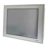
OMRON NS15-TX01S-V2 Programming Manual (683 pages)
NS-Series Programmable Terminals
Brand:
OMRON
| Category:
Touch terminals
| Size: 16.19 MB
Table of Contents
Table of Contents
7
How NS-Series Pts Work at FA Production Sites
14
NS-Series PT Operation
14
NS-Series PT Operation
15
NS-Series PT Functions
17
Differences between Models
20
Main NS-Series Functions
22
NS-Series Displays
24
Communicating with the Host
33
Host Registration and Address
33
Ethernet
33
Controller Link
33
NT Links
34
Host Link
35
Ethernet/Ip
35
PT Memory
35
System Configuration
40
Peripheral Devices
40
Connecting to the Host
43
Procedure before Operation
44
Section 2 Ns Series Functions
47
Project Configuration
48
Project Data
48
Project Properties
50
Display Colors
56
NS Series Screen Types
56
Screen Configuration
57
Screen Numbers
58
Screen Types
59
Screen Objects
63
Bit Memory ($B)
65
Internal Holding Memory ($HB/$HW)
65
Internal Memory
65
Word Memory ($W)
65
System Bit Memory ($SB)
66
System Memory
66
System Word Memory ($SW)
82
System Memory Compatibility with the NT Series
89
Communications Address Settings
94
Register Host
94
Communications Addresses
95
Directly Specifying Addresses
96
Tags
100
Fixed Objects
105
Registering/Using Library
111
Common Functional Object Functions
112
Table of Functional Object Settings
112
Address Settings (General Tab and Other Tabs)
113
Unit and Scale (General Tab)
116
Numeral Display and Storage Type (General Tab)
118
Date and Time Format (General Tab)
125
Text Attributes
127
Setting Colors (Color/Shape Tab)
132
Background
133
Selecting Shape (Color/Shape Tab)
134
Labels
136
Scroll Bars
140
Frames
141
Flicker (Extension Tab)
142
Write Settings (Extension Tab)
147
Passwords (Extension Tab)
151
Control Flags (Extension Tab)
158
Macro (Extension Tab)
159
Size/Position (Extension Tab)
160
Change Input Order
162
String Table
163
Buttons
166
Word Buttons
174
Command Buttons
182
Lamps
200
Word Lamps
204
Multifunction Objects
208
Functions that Can be Executed Using Multifunction Objects
210
Execution Conditions for Multifunction Objects
211
Safety Functions
212
Writing and Reading Communications Addresses
214
Canceling Multifunction Object Processing
215
Converting from Other Objects to Multifunction Objects
216
Functional Object Property Settings
217
Detailed Settings for each Function
225
Display and Input Objects
286
Numeral Display and Input
286
String Display and Input
294
Thumbwheel Switches
299
List Selection
304
Temporary Input Objects
312
Display
317
Text
317
Bitmaps
324
Level Meters
329
Analogue Meter
333
Video Display
338
Consecutive Line Drawings
343
Alarms and Events
345
Outline
345
Alarm/Event Display Objects
356
Alarm/Event Summary and History
361
Searching for Alarms and Events Using the Ladder Monitor
369
Data Logs
374
Outline
374
Data Log Graphs
383
Example Setting Procedure
394
Broken-Line Graphs
412
Data Blocks
425
What Is a Data Block?
425
Data Block Tables
436
Using Data Blocks
447
Date Object
453
System Clock
453
Time Objects
456
Machine Navigator Function
459
Contents Display
468
Usage Examples for Machine Navigator Function
473
Special Functions
478
Operation Log Function
478
Alarm/Event History Function
488
Data Log Function
490
Error Log Function
494
Screen Saver Function
496
Buzzer Function
498
Clock Function
500
Starting External Applications
501
Device Monitor Function
502
Video Configuration
526
Programming Console Functions
529
PLC Data Trace
533
System Settings and System Menu
545
Transferring Device Data
547
What Is Device Data Transfer?
547
Device Data Setting Dialog Box
548
Section 3 Using Pts
555
Procedure before Operation
556
Controlling Buzzers, Backlights, and Display
557
Sounding Buzzers
557
Stopping Buzzers
557
Controlling Backlights
558
Turning off Screen Display
558
Displaying Cleared Screens
558
Screen Display and Notification
560
Switching Screens
560
Finding Current Screen Numbers
564
Changing Numeral and Character String Display
565
Methods for Changing Numeral and Character String Display
565
Displaying Graphs
570
Changing Graph Displays
570
Inputting Numeral and Character Strings
572
Inputting Numerals
572
Inputting Character Strings
575
Using Alarm/Event Summary History Functions
577
Using Operation Log Functions
581
Settings for Operation Logs
582
Checking Operation Logs
582
Displaying and Setting System Clock
583
Displaying Date and Time
583
Setting Date and Time
583
Prohibiting and Allowing PT Operation
584
Prohibiting and Allowing System Menu Movement
584
Prohibiting and Allowing Input to All Screen Functional Objects
584
Prohibiting and Allowing Input for Individual Functional Objects
585
Using Memory Cards
586
Transferring Data Using Memory Cards
586
Saving Alarm/Event Histories to Memory Cards
586
Saving Data Logs to Memory Cards
586
Saving Operation Logs to Memory Cards
587
Saving Error Logs to Memory Cards
587
Saving Data Blocks to Memory Cards
587
Saving Captured Images to Memory Cards
587
Function Key Settings (NS15 Only)
588
Application
592
When Monitoring Bits Turn on
592
Always Reading PLC Word Contents
597
Changed Bit Status
599
For Numeral/String Input
602
For Button Operation by User
603
When Screens Are Switched
603
Errors
606
Error Messages
611
Troubleshooting Data Transfers from the CX-Designer
611
Troubleshooting Errors When Turning on Power
614
Troubleshooting Errors at Startup
617
Troubleshooting Errors When Switching Screens
618
Troubleshooting Errors for Functional Objects
620
Troubleshooting Errors During System Menu Operation
621
Communications Errors and Countermeasures
623
Troubleshooting Macros
633
Troubleshooting Errors with Ethernet/Ip Communications
635
Appendix-1 Specifications
642
A-1-1 Display Specifications
642
A-1-2 Specifications for Display Elements
646
A-1-3 Special Functions
650
Appendix-2 List of Models
651
A-2-1 PT Models
651
Appendix-3 PLC Memory Areas
653
A-3-1 OMRON C-Series PLC Memory Areas (same for 1:1 and 1:N NT Links)
653
A-3-2 OMRON CVM1 and CV-Series PLC Memory Areas
653
A-3-3 OMRON CS-Series CS1G, CS1H, CS1G-H, and CS1H-H PLC Memory Areas
654
A-3-4 OMRON CJ-Series CJ1G, CJ1G/H-H, CJ1M, and CJ2H PLC Memory Areas
655
A-3-5 List of Areas with Bit Access
656
Appendix-4 Addresses for Functional Objects
657
A-4-1 Using Direct Addresses
657
A-4-2 Using Tags
663
Appendix-5 Controller Link Network Status Read List
670
Appendix-6 Additional NS Series Functions
673
Advertisement
Advertisement
Related Products
OMRON NS15-TX Series
Omron NS15-TX01*-V2
Omron NS15-V2 Series
OMRON NS10-TV00 Series
OMRON NS10-TV01 Series
Omron NS12-TV01*-V2
Omron NS12-TS00B-V1
Omron NS12-TS01B-V1
Omron NS10-TV01B-V1
Omron NS15 B-V2 Series
Omron Categories
Blood Pressure Monitor
Controller
Accessories
Switch
Inverter
More Omron Manuals
Login
Sign In
OR
Sign in with Facebook
Sign in with Google
Upload manual
Upload from disk
Upload from URL