Sign In
Upload
Manuals
Brands
OMRON Manuals
Touch terminals
NS15-TX Series
OMRON NS15-TX Series Manuals
Manuals and User Guides for OMRON NS15-TX Series. We have
3
OMRON NS15-TX Series manuals available for free PDF download: Programming Manual, Setup Manual, Operation Manual
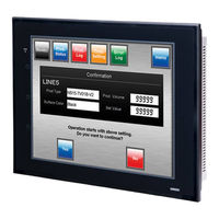
OMRON NS15-TX Series Programming Manual (682 pages)
NS-Series Programmable Terminals
Brand:
OMRON
| Category:
Touch terminals
| Size: 13.42 MB
Table of Contents
Table of Contents
7
How NS-Series Pts Work at FA Production Sites
14
NS-Series PT Operation
14
NS-Series PT Operation
15
NS-Series PT Functions
17
Differences between Models
20
Main NS-Series Functions
22
NS-Series Displays
24
Communicating with the Host
33
Host Registration and Address
33
Ethernet
33
Controller Link
33
NT Links
34
Host Link
35
Ethernet/Ip
35
PT Memory
35
System Configuration
41
Peripheral Devices
41
Connecting to the Host
44
Procedure before Operation
45
Section 2 Ns Series Functions
49
Project Configuration
50
Project Data
50
Project Properties
52
Display Colors
58
NS Series Screen Types
58
Screen Configuration
59
Screen Numbers
60
Screen Types
61
Screen Objects
65
Bit Memory ($B)
67
Internal Holding Memory ($HB/$HW)
67
Internal Memory
67
Word Memory ($W)
67
System Bit Memory ($SB)
68
System Memory
68
System Word Memory ($SW)
84
System Memory Compatibility with the NT Series
91
Communications Address Settings
96
Register Host
96
Communications Addresses
97
Directly Specifying Addresses
98
Tags
102
Fixed Objects
107
Registering/Using Library
113
Common Functional Object Functions
114
Table of Functional Object Settings
114
Address Settings (General Tab and Other Tabs)
115
Unit and Scale (General Tab)
118
Numeral Display and Storage Type (General Tab)
120
Date and Time Format (General Tab)
127
Text Attributes
129
Setting Colors (Color/Shape Tab)
134
Background
135
Selecting Shape (Color/Shape Tab)
136
Labels
138
Scroll Bars
142
Frames
143
Flicker (Extension Tab)
144
Write Settings (Extension Tab)
149
Passwords (Extension Tab)
153
Control Flags (Extension Tab)
160
Macro (Extension Tab)
161
Size/Position (Extension Tab)
162
Change Input Order
164
String Table
165
Buttons
168
Word Buttons
176
Command Buttons
184
Lamps
202
Word Lamps
206
Multifunction Objects
210
Functions that Can be Executed Using Multifunction Objects
212
Execution Conditions for Multifunction Objects
213
Safety Functions
214
Writing and Reading Communications Addresses
216
Canceling Multifunction Object Processing
217
Converting from Other Objects to Multifunction Objects
218
Functional Object Property Settings
219
Detailed Settings for each Function
227
Display and Input Objects
288
Numeral Display and Input
288
String Display and Input
296
Thumbwheel Switches
301
List Selection
306
Temporary Input Objects
314
Display
319
Text
319
Bitmaps
326
Level Meters
331
Analogue Meter
335
Video Display
340
Consecutive Line Drawings
345
Alarms and Events
347
Outline
347
Alarm/Event Display Objects
358
Alarm/Event Summary and History
363
Searching for Alarms and Events Using the Ladder Monitor
371
Data Logs
376
Outline
376
Data Log Graphs
385
Example Setting Procedure
396
Broken-Line Graphs
414
Data Blocks
427
What Is a Data Block?
427
Data Block Tables
438
Using Data Blocks
449
Date Object
455
System Clock
455
Time Objects
458
Machine Navigator Function
461
Contents Display
470
Usage Examples for Machine Navigator Function
475
Special Functions
480
Operation Log Function
480
Alarm/Event History Function
490
Data Log Function
492
Error Log Function
496
Screen Saver Function
498
Buzzer Function
500
Clock Function
502
Starting External Applications
503
Device Monitor Function
504
Video Configuration
528
Programming Console Functions
531
PLC Data Trace
535
System Settings and System Menu
547
Transferring Device Data
549
What Is Device Data Transfer?
549
Device Data Setting Dialog Box
550
Section 3 Using Pts
557
Procedure before Operation
558
Controlling Buzzers, Backlights, and Display
559
Sounding Buzzers
559
Stopping Buzzers
559
Controlling Backlights
560
Turning off Screen Display
560
Displaying Cleared Screens
560
Screen Display and Notification
562
Switching Screens
562
Finding Current Screen Numbers
566
Changing Numeral and Character String Display
567
Methods for Changing Numeral and Character String Display
567
Displaying Graphs
572
Changing Graph Displays
572
Inputting Numeral and Character Strings
574
Inputting Numerals
574
Inputting Character Strings
577
Using Alarm/Event Summary History Functions
579
Using Operation Log Functions
583
Settings for Operation Logs
584
Checking Operation Logs
584
Displaying and Setting System Clock
585
Displaying Date and Time
585
Setting Date and Time
585
Prohibiting and Allowing PT Operation
586
Prohibiting and Allowing System Menu Movement
586
Prohibiting and Allowing Input to All Screen Functional Objects
586
Prohibiting and Allowing Input for Individual Functional Objects
587
Using Memory Cards
588
Transferring Data Using Memory Cards
588
Saving Alarm/Event Histories to Memory Cards
588
Saving Data Logs to Memory Cards
588
Saving Operation Logs to Memory Cards
589
Saving Error Logs to Memory Cards
589
Saving Data Blocks to Memory Cards
589
Saving Captured Images to Memory Cards
589
Function Key Settings (NS15 Only)
590
Application
594
When Monitoring Bits Turn on
594
Always Reading PLC Word Contents
599
Changed Bit Status
601
For Numeral/String Input
604
For Button Operation by User
605
When Screens Are Switched
605
Errors
608
Error Messages
613
Troubleshooting Data Transfers from the CX-Designer
613
Troubleshooting Errors When Turning on Power
616
Troubleshooting Errors at Startup
619
Troubleshooting Errors When Switching Screens
620
Troubleshooting Errors for Functional Objects
622
Troubleshooting Errors During System Menu Operation
623
Communications Errors and Countermeasures
625
Troubleshooting Macros
635
Troubleshooting Errors with Ethernet/Ip Communications
637
Appendix-1 Specifications
644
A-1-1 Display Specifications
644
A-1-2 Specifications for Display Elements
648
A-1-3 Special Functions
652
Appendix-2 List of Models
653
A-2-1 PT Models
653
Appendix-3 PLC Memory Areas
655
A-3-1 OMRON C-Series PLC Memory Areas (same for 1:1 and 1:N NT Links)
655
A-3-2 OMRON CVM1 and CV-Series PLC Memory Areas
655
A-3-3 OMRON CS-Series CS1G, CS1H, CS1G-H, and CS1H-H PLC Memory Areas
656
A-3-4 OMRON CJ-Series CJ1G, CJ1G/H-H, CJ1M, and CJ2H PLC Memory Areas
657
A-3-5 List of Areas with Bit Access
658
Appendix-4 Addresses for Functional Objects
659
A-4-1 Using Direct Addresses
659
A-4-2 Using Tags
665
Appendix-5 Controller Link Network Status Read List
672
Appendix-6 Additional NS Series Functions
675
Advertisement
OMRON NS15-TX Series Setup Manual (335 pages)
NS-Series NS-Series
Brand:
OMRON
| Category:
Touch terminals
| Size: 7.18 MB
Table of Contents
Table of Contents
4
About this Manual
9
Related Manuals
10
Terminology
11
Introduction
12
Overview
23
Section 1 Overview
23
Types, and Communications Methods.
24
This Section Provides an Overview of the NS-Series Pts, Including Functions, Features, Connection
24
NS-Series PT Functions and Operation
24
PT Functions for FA Manufacturing Sites
24
NS-Series PT Operating System
25
Communications with the Host
27
What Is an NT Link
28
Ethernet
28
Controller Link
28
Host Link
28
Connecting to a Temperature Controller
28
Memory Link Connections
29
Communicating with Other Devices
29
Ethernet/Ip
29
System Configuration
30
Supported Peripheral Devices
30
Procedure for Running NS-Series Pts
32
Before Connecting
35
Section 2 before Connecting
35
Connecting the Host
36
Communications Types and Connection Methods
36
Part Names and Functions
42
Installing the PT and Connecting Peripheral Devices
55
Installing the PT
57
Installation Environment
57
Installing RS-232C/RS-422A Converters
58
Mounting the PT to the Control Panel
58
Connecting the Power Supply
61
Wiring the Ground Wire
62
Peripheral Device Connection Limitations
62
Starting the PT
64
Operation at Startup
64
Starting the PT for the First Time
66
Connecting the CX-Designer
68
Connecting Via RS-232C or Ethernet
68
Connecting Via USB
68
Connecting Via a Modem
70
Connecting to Bar Code Readers
71
Connection Methods
71
Setting Bar Code Readers
72
Data Format
73
Bar Code Input
73
Connecting to Printers
74
Connecting to a Printer Compatible with ESC/P Raster and BJ Raster
74
Connecting a Pictbridge-Compatible Printer
75
Using Memory Cards
77
Installation
78
Replacing the System Program
79
Transferring Data with Memory Cards
80
Installing the Video Input Unit
87
Video Input Unit Components
87
Nomenclature and Functions
87
Installation Method for Video Input Unit
88
Connecting to Video Input Connectors
93
3-8 Installing the Controller Link Interface Unit
99
Installing the Controller Link Interface Unit
99
Nomenclature and Functions
99
Installation Method for Controller Link Interface Unit
102
Wiring
109
Connecting a Monitor
115
External Brightness Adjustment
116
RS-232C/RS-422A Selector DIP Switch
117
Connecting the Host to Serial Port
119
Connection).
120
On Connecting to Another Company's PLC, Refer to the Host Connection Manual (Multivendor
120
Communications, Refer to the Host Connection Manual (Temp. Control, Memlink). for Details
120
1:1 Host Connection
120
Connection Methods
120
Unit Setting Methods
122
1:N Host Connection
125
Connection Methods
125
Unit Setting Methods
125
High-Speed 1:N NT Link
136
Unit Setting Methods
137
Recommended Connector Cables
145
Section 5 Connecting to Host Via Ethernet or Controller Link
147
Connecting to Host Via Ethernet
148
Host Types and Settings
149
Connecting to the Host Using Controller Link
164
What Is a Controller Link Network
164
Data Links
165
Troubleshooting Using Indicators
170
Connecting to Host Via Ethernet/Ip
173
What Is Ethernet/Ip
173
Setting Individual Units
174
System Menu Operations
177
Operating Modes and System Menu
179
Mode Configuration
179
System Menu Configuration
179
Overview of Menu Items
180
Using the System Menu
183
Initializing and Saving Data and Removing the Memory Card
186
Screen Data Area Format
187
Initializing or Saving the Alarm/Event History
188
Initializing and Saving Data Log
190
Initializing and Saving the Operation Log
191
Initializing and Saving the Error Log
193
Language Selection
194
Removing the Memory Card
195
Initializing Internal Holding Memories ($HB/$HW)
196
PT Settings
197
Start-Up Wait Time
199
Screen Saver
200
Key Press Sound
201
Buzzer Sound
201
Backlight Brightness
202
Calendar Check
203
Printer Type
204
Printing Mode
204
Orientation
205
Changing Values in Device Monitor Setting
205
Contrast (NS5-SQ@@/NS5-MQ@@ Only)
205
CJK Han Unification Priority
206
Alarm Monitor Registration Procedure
206
(NS15/12/10/8 Only)
207
Setting the Tag Update Notification Message
207
Time to Switch to System Menu (NS12, NS10, NS8, or NS5)
207
Double-Touch Interval (NS15 Only)
208
Analog RGB Output (NS15 Only)
208
Project Settings
209
Project Title
209
Number of Labels
210
Initial Screen
210
Initial Label
210
Alarm/Event History Recording Method
210
Data Log Recording Method
210
Operation Log Recording Method
211
Error Log Recording Method
211
System Memory
211
Setting Passwords
212
Changing the Password
212
Setting the Password Function
213
Communications Settings
215
Communications Conditions
215
Setting 1:1 NT Link
217
Setting High-Speed 1:N NT Links (Standard, High-Speed)
218
Setting Ethernet
218
Setting the Controller Link Network
221
Setting Bar Code Readers
222
Modem Settings
223
Screen Data Check
224
Special Screens
225
Alarm History
226
Operation Log
227
Error Log
228
Device Monitor
229
Communication Test
231
Video Configuration
233
USB Device List
235
Display Capture Data
236
Memory Card Transfers
237
External Application Startup
239
Version Display
240
PLC Data Trace (NS15, NS12, NS10, and NS8 Only)
240
Hardware Check
242
LCD Check
242
Touch Switch Check
243
Touch Panel Calibration (NS15 Only)
243
Starting Operations
244
Verifying Tags
246
Maintenance and Troubleshooting
249
Maintenance
250
Replacing the Battery
250
Inspection and Cleaning
252
Troubleshooting and Maintenance
254
Requesting a Replacement PT
262
Appendices
263
Appendix 1 Specifications
265
A-1-1 General Specifications
265
A-1-2 Characteristics
267
A-1-3 Communications Specifications
270
Appendix 1 Specifications
270
Appendix 2 Dimensions
274
Appendix 3 Using NS-AL002 Converters
283
A-3-1 Dimensions
283
A-3-2 Mounting and Removing
284
A-3-3 Specifications
284
A-3-4 DIP Switch Settings
285
A-3-5 Pin Arrangement
286
A-3-6 Handling the Shield on RS-422A/485 Cables
287
A-3-7 Connection Example
290
Appendix 4 Using NT-AL001 Converters
291
A-4-1 Dimensions
291
A-4-2 Methods for Mounting and Removal
291
A-4-3 Specifications
293
A-4-4 DIP Switch Settings
294
A-4-5 Pin Arrangement
295
A-4-6 Block Diagram
296
Appendix 5 Preparing Connecting Cables
297
A-5-1 Cable Preparation
297
A-5-2 Soldering
298
A-5-3 Hood Assembly
298
A-5-4 Preparing Connecting Cables for Host Connection
299
Appendix 6 Preparing Cables for Computer Connection
303
A-6-1 Connecting Cable Assembly
303
Appendix 7 Preparing Connecting Cables for Bar Code Readers
305
Appendix 8 Standard Models
306
Appendix 9 List of Optional Products
322
A-9-1 Anti-Reflection Sheets: NS15-KBA04, NS12-KBA04, NS7-KBA04, NT30-KBA04
322
A-9-1 Anti-Reflection Sheets: NS15-KBA04, NS12-KBA04, NS7-KBA04
322
Nt30-Kba04
322
A-9-2 Protective Covers: NS15-KBA05N, NS12-KBA05(N), NS7-KBA05(N NT31C-KBA05(N)
323
A-9-3 NT30-KBA01 Chemical-Resistant Cover
324
A-9-4 Replacement Battery: CJ1W-BAT01
324
A-9-5 Recommended Memory Cards
325
A-9-6 NS-CLK21 Controller Link Interface Unit
325
A-9-7 NS-CA001/CA002 Video Input Unit
325
A-9-8 Attachments: NS12-ATT01(B)/NS12-ATT02/NS8-ATT01/ NS8-ATT02
325
A-9-9 NS-USBEXT-1M USB Relay Cable
326
Appendix 10 System Memory List
327
Appendix 11 Differences between "-V1"/"-V2" Models and Other Models
330
Appendix 12 NS5 System Menu
332
OMRON NS15-TX Series Operation Manual (44 pages)
Programmable Terminals , Host Connection Manual: Host Link
Brand:
OMRON
| Category:
Touch terminals
| Size: 2.67 MB
Advertisement
Advertisement
Related Products
Omron NS15-TX01*-V2
Omron NS15-V2 Series
Omron NS15-TX01S-V2
OMRON NS12-TS Series
Omron NS12-TS00 V1 Series
Omron NS12-TS00 V2 Series
Omron NS12-TS01 V2 Series
Omron NS12-TV00*-V2
Omron NS12-TV01*-V1
Omron NS10-TV00 V1 Series
OMRON Categories
Blood Pressure Monitor
Controller
Accessories
Switch
Inverter
More OMRON Manuals
Login
Sign In
OR
Sign in with Facebook
Sign in with Google
Upload manual
Upload from disk
Upload from URL