Sign In
Upload
Manuals
Brands
Motorola Manuals
Portable Radio
ASTRO MT 1500
Motorola ASTRO MT 1500 Manuals
Manuals and User Guides for Motorola ASTRO MT 1500. We have
4
Motorola ASTRO MT 1500 manuals available for free PDF download: Service Manual, Basic Service Manual, User Manual
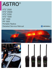
Motorola ASTRO MT 1500 Service Manual (817 pages)
Brand:
Motorola
| Category:
Portable Radio
| Size: 44.21 MB
Table of Contents
Foreword
2
Safety Information
2
Manual Revisions
2
Computer Software Copyrights
2
Documentation Copyrights
2
Disclaimer
2
Trademarks
2
Document History
3
Table of Contents
5
Chapter 1 Introduction
25
General
25
Notations Used in this Manual
25
Chapter 2.1 VHF Overall Characteristics
27
Introduction
27
Analog Mode of Operation-Receiving
27
Analog Mode of Operation-Transmitting
28
ASTRO Mode (Digital Mode) of Operation
28
Main Board Overview
28
Vocoder Circuitry Overview
29
Chapter 2.2 UHF1 Overall Characteristics
31
Introduction
31
Analog Mode of Operation-Receiving
31
Analog Mode of Operation-Transmitting
32
ASTRO Mode (Digital Mode) of Operation
32
Main RF Board Overview
32
Vocoder Circuitry Overview
33
Chapter 2.3 UHF2 Overall Characteristics
35
Introduction
35
Analog Mode of Operation-Receiving
35
Analog Mode of Operation-Transmitting
36
ASTRO Mode (Digital Mode) of Operation
36
Main RF Board Overview
36
Vocoder Circuitry Overview
37
Chapter 2.4 700/800 Mhz Overall Characteristics
39
Introduction
39
Analog Mode of Operation-Receiving
39
Analog Mode of Operation-Transmitting
40
ASTRO Mode (Digital Mode) of Operation
40
Main Board Overview
40
Vocoder Circuitry Overview
41
Chapter 2.5 900Mhz Overall Characteristics
43
Introduction
43
Analog Mode of Operation-Receiving
43
Analog Mode of Operation-Transmitting
44
ASTRO Mode (Digital Mode) of Operation
44
Main Board Overview
44
Vocoder Circuitry Overview
45
Chapter 3.1 VHF Radio Power
47
Introduction
47
Radio Power up or down
47
General
47
B+ Routing for VHF Band Main Board
48
Figure 3.1-1.B+ Routing for VHF Main Board
48
B+ and +5V Routing for VOCON
49
Figure 3.1-2.XTS 2500/XTS 2500I DC Distribution (for All Other Kits)
49
Table 3.1-1. Power Supply Configuration for VOCON Section
50
Chapter 3.2 UHF1 Radio Power
51
Introduction
51
Radio Power up or down
51
General
51
B+ Main Board Routing
52
Figure 3.2-1.B+ Routing for Main Board
52
B+ and +5V Routing for VOCON
53
Figure 3.2-2.XTS 2500/XTS 2500I DC Distribution (for All Other Kits)
53
Table 3.2-1. Power Supply Configuration for VOCON Section
54
Chapter 3.3 UHF2 Radio Power
55
Introduction
55
Radio Power up or down
55
General
55
B+ Routing for UHF2 Band Main Board
56
Figure 3.3-1.B+ Routing for Main Board
56
B+ and +5V Routing for VOCON
57
Figure 3.3-2.XTS 2500/XTS 2500I DC Distribution (for All Other Kits)
57
Table 3.3-1. Power Supply Configuration for VOCON Section
58
Chapter 3.4 700/800 Mhz Radio Power
59
Introduction
59
Radio Power up or down
59
General
59
B+ Routing for 700/800 Mhz Band Main Board
60
Figure 3.4-1.B+ Routing for 700/800 Mhz Main Board
60
B+ and +5V Routing for VOCON
61
Figure 3.4-2.XTS 2500/XTS 2500I DC Distribution (for All Other Kits)
61
Table 3.4-1. Power Supply Configuration for VOCON Section
62
Chapter 3.5 900 Mhz Radio Power
63
Introduction
63
Radio Power up or down
63
General
63
B+ Routing for 900 Mhz Band Main Board
64
Figure 3.5-1.B+ Routing for 900Mhz Main Board
64
B+ and +5V Routing for VOCON
65
Figure 3.5-2.XTS 2500/XTS 2500I DC Distribution (for All Other Kits)
65
Table 3.5-1. Power Supply Configuration for VOCON Section
66
Chapter 4.1 VHF Detailed Theories of Operation
67
Introduction
67
Frequency Synthesis
67
Antenna Switch
68
Receiver
68
Front End
69
Back End
69
Transmitter
70
VOCON Functional Blocks
71
Controller and Memory Section
71
Patriot IC (U800)
71
Flash Memory (U803)
74
Sram (U804)
74
Figure 4.1-1.Controller Memory Interface
75
Audio and Power Section
76
Mako IC (U701)
76
Audio Power Amplifier
77
Audio Pre-Amplifier
77
Regulator
77
Interface Support Section
78
Mako IC U701
78
ESD Protection Circuitry
79
Universal Connector (Side Connector) Interface Circuitry
79
Figure 4.1-2.Universal (Side) Connector
80
Figure 4.1-3.VOCON Connector J650
80
Table 4.1-1. Option Select Functions
80
The Option Board
81
Encryption Module
82
Table 4.1-2. Encryption Module Software Kits and Algorithms
82
System Clocks
83
Transmit Audio Path
83
Figure 4.1-4.VOCON Transmit Audio Path
83
Receive Audio Path
84
Figure 4.1-5.VOCON Receive Audio Path
84
Chapter 4.2 UHF1 Detailed Theories of Operation
85
Introduction
85
Frequency Synthesis
85
Antenna Switch
86
Receiver
87
Front End
87
Back End
88
Transmitter
88
VOCON Functional Blocks
89
Controller and Memory Section
89
Patriot IC (U800)
89
Sram (U804)
92
Figure 4.2-1.Controller Memory Interface
93
Flash Memory (U803)
93
Audio and Power Section
94
Mako IC (U701)
94
Audio Power Amplifier
95
Audio Pre-Amplifier
95
Regulator
95
Interface Support Section
96
Mako IC U701
96
ESD Protection Circuitry
97
Universal Connector (Side Connector) Interface Circuitry
97
Figure 4.2-2.Universal (Side) Connector
98
Figure 4.2-3.VOCON Connector J650
98
Table 4.2-1. Option Select Functions
98
The Option Board
99
Encryption Module
100
Table 4.2-2. Encryption Module Software Kits and Algorithms
100
Figure 4.2-4.VOCON Transmit Audio Path
101
System Clocks
101
Transmit Audio Path
101
Figure 4.2-5.VOCON Receive Audio Path
102
Receive Audio Path
102
Chapter 4.3 UHF2 Detailed Theories of Operation
103
Introduction
103
Frequency Synthesis
103
Antenna Switch
104
Receiver
105
Front End
105
Back End
106
Transmitter
106
VOCON Functional Blocks
107
Controller and Memory Section
107
Patriot IC (U800)
107
Flash Memory (U803)
110
Sram (U804)
110
Figure 4.3-1.Controller Memory Interface
111
Audio and Power Section
112
Mako IC (U701)
112
Audio Power Amplifier
113
Audio Pre-Amplifier
113
Regulator
113
Interface Support Section
114
Mako IC U701
114
ESD Protection Circuitry
115
Universal Connector (Side Connector) Interface Circuitry
115
Figure 4.3-2.Universal (Side) Connector
116
Figure 4.3-3.VOCON Connector J650
116
Table 4.3-1. Option Select Functions
116
The Option Board
117
Encryption Module
118
Table 4.3-2. Encryption Module Software Kits and Algorithms
118
Figure 4.3-4.VOCON Transmit Audio Path
119
System Clocks
119
Transmit Audio Path
119
Figure 4.3-5.VOCON Receive Audio Path
120
Receive Audio Path
120
Chapter 4.4 700/800 Mhz Detailed Theories of Operation
121
Introduction
121
Frequency Synthesis
121
Antenna Switch
122
Receiver
123
Front End
123
Back End
124
Transmitter
124
VOCON Functional Blocks
125
Controller and Memory Section
125
Patriot IC (U800)
125
Flash Memory (U803)
128
Sram (U804)
128
Figure 4.4-1.Controller Memory Interface
129
Audio and Power Section
130
Mako IC (U701)
130
Audio Power Amplifier
131
Audio Pre-Amplifier
131
Regulator
131
Interface Support Section
132
Mako IC U701
132
ESD Protection Circuitry
133
Universal Connector (Side Connector) Interface Circuitry
133
Figure 4.4-2.Universal (Side) Connector
134
Figure 4.4-3.VOCON Connector J650
134
Table 4.4-1. Option Select Functions
134
The Option Board
135
Encryption Module
136
Table 4.4-2. Encryption Module Software Kits and Algorithms
136
System Clocks
137
Transmit Audio Path
137
Figure 4.4-4.VOCON Transmit Audio Path
138
Receive Audio Path
138
Figure 4.4-5.VOCON Receive Audio Path
139
Chapter 4.5 900 Mhz Detailed Theories of Operation
141
Introduction
141
Frequency Synthesis
141
Antenna Switch
142
Receiver
143
Front End
143
Back End
144
Transmitter
144
VOCON Functional Blocks
145
Controller and Memory Section
145
Patriot IC (U800)
145
Flash Memory (U803)
148
Sram (U804)
148
Figure 4.5-1.Controller Memory Interface
149
Audio and Power Section
150
Mako IC (U701)
150
Audio Power Amplifier
151
Audio Pre-Amplifier
151
Interface Support Section
151
Regulator
151
Mako IC U701
152
ESD Protection Circuitry
153
Universal Connector (Side Connector) Interface Circuitry
153
Figure 4.5-2.Universal (Side) Connector
154
Figure 4.5-3.VOCON Connector J650
154
Table 4.5-1. Option Select Functions
154
The Option Board
154
Encryption Module
156
Table 4.5-2. Encryption Module Software Kits and Algorithms
156
Figure 4.5-4.VOCON Transmit Audio Path
157
System Clocks
157
Transmit Audio Path
157
Figure 4.5-5.VOCON Receive Audio Path
158
Receive Audio Path
158
Chapter 5 Troubleshooting Procedures
159
Introduction
159
Handling Precautions
159
Voltage Measurement and Signal Tracing
159
Standard Bias Table
160
Table 5-1. Standard Operating Bias
160
Power-Up Self-Check Errors
161
Table 5-2. Power-Up Self-Check Error Codes
161
Operational Error Codes
162
Power-Up, Self-Check Diagnostics, and Repair (Not for Field Use)
162
Table 5-3. Operational Error Code Displays
162
Table 5-4. Additional Error Code Action Items
162
Chapter 6.1 VHF Troubleshooting Charts
165
Introduction
165
List of Troubleshooting Flowcharts
165
VHF Radio Main Troubleshooting Chart
166
Radio Power-Up Fail Troubleshooting Chart (1 of 3)
167
Radio Power-Up Fail Troubleshooting Chart (2 of 3)
168
Radio Power-Up Fail Troubleshooting Chart (3 of 3)
169
DC Supply Fail Troubleshooting Chart (1 of 3)
170
DC Supply Fail Troubleshooting Chart (2 of 3)
171
Volume Set Error Troubleshooting Chart
174
Top/Side Button Error Troubleshooting Chart
176
No Display Troubleshooting Chart (1 of 3)
177
VOCON Transmit Audio Troubleshooting Chart (1 of 2)
183
VOCON Transmit Audio Troubleshooting Chart (2 of 2)
184
No Transmit Deviation Troubleshooting Chart
185
Secure Hardware Failure
187
Chapter 6.2 UHF1 Troubleshooting Charts
189
Introduction
189
List of Troubleshooting Flowcharts
189
UHF Range 1 Radio Main Troubleshooting Chart
190
Radio Power-Up Fail Troubleshooting Chart (1 of 3)
191
Radio Power-Up Fail Troubleshooting Chart (2 of 3)
192
Radio Power-Up Fail Troubleshooting Chart (3 of 3)
193
DC Supply Fail Troubleshooting Chart (1 of 3)
194
DC Supply Fail Troubleshooting Chart (2 of 3)
195
DC Supply Fail Troubleshooting Chart (3 of 3)
196
Button Test Troubleshooting Chart
213
Volume Set Error Troubleshooting Chart
213
Zone/Channel Select Error Troubleshooting Chart
213
Top/Side Button Error Troubleshooting Chart
213
VOCON Receive Audio Troubleshooting Chart
213
No Transmit Deviation Troubleshooting Chart
213
Secure Hardware Failure
213
Chapter 6.3 UHF2 Troubleshooting Charts
213
Introduction
213
List of Troubleshooting Flowcharts
213
UHF Range 2 Radio Main Troubleshooting Chart
214
Radio Power-Up Fail Troubleshooting Chart (1 of 3)
215
Radio Power-Up Fail Troubleshooting Chart (2 of 3)
216
Radio Power-Up Fail Troubleshooting Chart (3 of 3)
217
DC Supply Fail Troubleshooting Chart (1 of 3)
218
DC Supply Fail Troubleshooting Chart (2 of 3)
219
Volume Set Error Troubleshooting Chart
222
Zone/Channel Select Error Troubleshooting Chart
223
Top/Side Button Error Troubleshooting Chart
224
No Display Troubleshooting Chart (1 of 3)
225
No Display Troubleshooting Chart (2 of 3)
226
VOCON Transmit Audio Troubleshooting Chart (1 of 2)
231
VOCON Transmit Audio Troubleshooting Chart (2 of 2)
232
No Transmit Deviation Troubleshooting Chart
233
Secure Hardware Failure
235
Chapter 6.4 700/800 Mhz Troubleshooting Charts
237
Introduction
237
List of Troubleshooting Flowcharts
237
700/800 Mhz Radio Main Troubleshooting Chart
238
Radio Power-Up Fail Troubleshooting Chart (1 of 3)
239
Radio Power-Up Fail Troubleshooting Chart (2 of 3)
240
Radio Power-Up Fail Troubleshooting Chart (3 of 3)
241
DC Supply Fail Troubleshooting Chart (1 of 3)
242
DC Supply Fail Troubleshooting Chart (2 of 3)
243
DC Supply Fail Troubleshooting Chart (3 of 3)
244
Volume Set Error Troubleshooting Chart
246
Top/Side Button Error Troubleshooting Chart
261
VOCON Receive Audio Troubleshooting Chart
261
No Transmit Deviation Troubleshooting Chart
261
Secure Hardware Failure
261
Chapter 6.5 900 Mhz Troubleshooting Charts
261
Introduction
261
List of Troubleshooting Flowcharts
261
900 Mhz Radio Main Troubleshooting Chart
262
Radio Power-Up Fail Troubleshooting Chart (1 of 3)
263
Radio Power-Up Fail Troubleshooting Chart (2 of 3)
264
Radio Power-Up Fail Troubleshooting Chart (3 of 3)
265
DC Supply Fail Troubleshooting Chart (1 of 3)
266
DC Supply Fail Troubleshooting Chart (2 of 3)
267
Volume Set Error Troubleshooting Chart
270
Top/Side Button Error Troubleshooting Chart
272
No Display Troubleshooting Chart (1 of 3)
273
No Display Troubleshooting Chart (2 of 3)
274
No Display Troubleshooting Chart (3 of 3)
275
900 Mhz Receive RF Troubleshooting Chart
276
VOCON Receive Audio Troubleshooting Chart
277
VOCON Transmit Audio Troubleshooting Chart (1 of 2)
279
VOCON Transmit Audio Troubleshooting Chart (2 of 2)
280
No Transmit Deviation Troubleshooting Chart
281
Secure Hardware Failure
283
Chapter 7.1 VHF Troubleshooting Waveforms
285
Introduction
285
List of Waveforms
285
Table 7.1-1. List of Waveforms
285
RF Test Points
286
Figure 7.1-1.RF Block Diagram Test Points
286
Table 7.1-2. RF Block Diagram Probe/Test Points
287
Main Circuit Board RF Shield Locations
288
Table 7.1-3. Main Circuit Board Side 1 RF Shields
288
Table 7.1-4. Main Circuit Board Side 2 RF Shields
289
PP1 Antenna Input
290
PP2 TX Signal at Harmonic Filter Input
291
PP3 Coupler RF out
292
PP4 TX Signal at PA
293
TP5 Coupler RF Feedback to PCIC
294
TP6 PCIC Control Voltage
295
Pp7 Tx lo
296
PP8 Higher Level Voltage Multiplier
297
PP9 Superfilter Output
298
PP11 Prescalar Input to Fracn Synthesizer
299
PP12 Reference Crystal Output
300
TP13 Mod in
301
TP14 1St lo Control Voltage
302
PP15 VCO Output
303
PP17 Frequency out (16.8 Mhz)
304
PP18 RX RF Input at Antenna Switch
305
PP19 Antenna Switch Bias
306
PP20 Preselector Tuning Voltage
307
PP22 Analog 5V
308
PP23 Preselector 1 Output
309
PP24 Low-Noise Amplifier Output
310
PP25 Preselector 2 Output
311
PP26 Mixer out (IF)
312
PP27 Crystal Filter out
313
PP28 Abacus Analog 3V
314
PP29 2Nd lo Control Voltage
315
PP30 2Nd lo VCO Buffer Output
316
PP31 Analog 5V DC
317
PP32 Abacus Digital 3V
318
TX Audio 1 Khz Tone
331
Mhz Buffer Input and Output
331
Khz Clock Outputs
331
SPI B Data
331
RX Serial Audio Port (SAP)
331
List of Waveforms
331
Table 7.2-1. List of Waveforms
331
RF Test Points
332
Figure 7.2-1.RF Block Diagram Test Points
332
Table 7.2-2. RF Block Diagram Probe/Test Points
333
Main Circuit Board RF Shield Locations
334
Table 7.2-3. Main Circuit Board Side 1 RF Shields
334
Table 7.2-4. Main Circuit Board Side 2 RF Shields
335
PP1 Antenna Input
336
PP2 TX Signal at Harmonic Filter Input
337
PP3 Coupler RF out
338
PP4 TX Signal at PA
339
TP5 Coupler RF Feedback to PCIC
340
TP6 PCIC Control Voltage
341
Pp7 Tx lo
342
TP14 1St lo Control Voltage
348
PP15 VCO Output
349
PP17 Frequency out (19.2 Mhz)
351
PP26 Mixer out (IF)
359
PP31 Analog 5V DC
364
PP32 Abacus Digital 3V
365
TX Audio 1 Khz Tone
379
Mhz Buffer Input and Output
379
Khz Clock Outputs
379
SPI B Data
379
RX Serial Audio Port (SAP)
379
Introduction
379
List of Waveforms
379
Table 7.3-1. List of Waveforms
379
RF Test Points
380
Figure 7.3-1.RF Block Diagram Test Points
380
Table 7.3-2. RF Block Diagram Probe/Test Points
381
Main Circuit Board RF Shield Locations
382
Table 7.3-3. Main Circuit Board Side 1 RF Shields
382
Table 7.3-4. Main Circuit Board Side 2 RF Shields
383
PP1 Antenna Input
384
PP2 TX Signal at Harmonic Filter Input
385
PP3 Coupler RF out
386
PP4 TX Signal at PA
387
TP5 Coupler RF Feedback to PCIC
388
Pp7 Tx lo
390
PP32 Abacus Digital 3V
412
TX Audio 1 Khz Tone
425
Mhz Buffer Input and Output
425
Khz Clock Outputs
425
SPI B Data
425
RX Serial Audio Port (SAP)
425
Introduction
425
List of Waveforms
425
Table 7.4-1. List of Waveforms
425
RF Test Points
426
Figure 7.4-1.RF Block Diagram Test Points
426
Table 7.4-2. RF Block Diagram Probe/Test Points
427
Main Circuit Board RF Shield Locations
428
Table 7.4-3. Main Circuit Board Side 1 RF Shields
428
Table 7.4-4. Main Circuit Board Side 2 RF Shields
429
PP1 Antenna Input
430
PP2 TX Signal at Harmonic Filter Input
431
PP3 Coupler RF out
432
PP4 TX Signal at PA
433
TP5 Coupler RF Feedback to PCIC
434
Pp7 Tx lo
436
Tp10 Trb
439
PP32 Abacus Digital 3V
461
TX Audio 1 Khz Tone
475
Mhz Buffer Input and Output
475
Khz Clock Outputs
475
SPI B Data
475
RX Serial Audio Port (SAP)
475
Introduction
475
List of Waveforms
475
Table 7.5-1. List of Waveforms
475
RF Test Points
476
Figure 7.5-1.RF Block Diagram Test Points
476
Table 7.5-2. RF Block Diagram Probe/Test Points
477
Main Circuit Board RF Shield Locations
478
Table 7.5-3. Main Circuit Board Side 1 RF Shields
478
Table 7.5-4. Main Circuit Board Side 2 RF Shields
479
PP1 Antenna Input
480
PP2 TX Signal at Harmonic Filter Input
481
PP3 Coupler RF out
482
PP4 TX Signal at PA
483
TP5 Coupler RF Feedback to PCIC
484
Pp7 Tx lo
486
Tp10 Trb
489
SPI B Data
515
PP33 SPI Data
517
PP35 Universal Chip Select
519
TP37 RX SSI Data
521
TP39 RX SSI Frame Sync
523
Introduction
525
Tables
525
Table 8.1-1. Main Board to Keypad Board Flex Assembly (J601)
525
Table 8.1-2. Main Board to Universal (Side) Connector Flex Assembly (J650)
527
Table 8.1-3. FLASH (U803) Pinout
527
Table 8.1-4. SRAM (U804) Pinout
530
Table 8.1-5. Patriot MCU/DSP (U800) Pinout
531
Table 8.1-6. MAKO (U701) Pinout
540
Advertisement
Motorola ASTRO MT 1500 Basic Service Manual (124 pages)
Brand:
Motorola
| Category:
Portable Radio
| Size: 16.24 MB
Table of Contents
Computer Software Copyrights
4
Document History
5
Table of Contents
7
Table of Contents
8
List of Figures
11
Related Manuals
14
Commercial Warranty
15
Limited Warranty
15
Motorola Communication Products
15
II. General Provisions
15
What this Warranty Covers and for How Long
15
How to Get Warranty Service
16
III. State Law Rights
16
What this Warranty Does Not Cover
16
Patent and Softwarep Provisions
17
VII. Governing Law
17
Specifications
19
Portable Radio Model Numbering System
19
Specifications for VHF Radios
20
ASTRO XTS 2500/XTS 2500I/XTS 2250 Model Chart
21
ASTRO XTS 2500/XTS 2500I/2250 Model Chart (Continued)
22
ASTRO XTS 1500/MT 1500 Model Chart
23
PR 1500 Model Chart
24
Specifications for UHF Range 1 Radios
25
ASTRO XTS 2500/XTS 2500I/XTS 2250 Model Chart
26
ASTRO XTS 2500/XTS 2500I/XTS 2250 Model Chart (Continued)
27
ASTRO XTS 2500/XTS 2500I/XTS 2250 Model Chart
28
ASTRO XTS 1500/MT 1500 Model Chart
29
PR 1500 Model Chart
30
Specifications for UHF Range 2 Radios
31
ASTRO XTS 2500/XTS 2500I/XTS 2250 Model Chart
32
ASTRO XTS 2500/XTS 2500I/XTS 2250 Model Chart (Continued)
33
ASTRO XTS 1500/MT 1500 Model Chart
34
PR 1500 Model Chart
35
Specifications for 700 Mhz/800 Mhz Radios
36
ASTRO XTS 2500/XTS 2500I/XTS 2250 Model Chart
37
ASTRO XTS 2500/XTS 2500I/XTS 2250 Model Chart (Continued)
38
ASTRO XTS 2500/XTS 2500I/XTS 2250 Model Chart (Continued)
39
ASTRO XTS 1500/MT 1500 Model Chart
40
Specifications for 900 Mhz Radios
41
ASTRO XTS 2500/XTS 2500I/XTS 2250 Model Chart
42
ASTRO XTS 1500/MT 1500 Model Chart
43
1 Introduction
45
General
45
Notations Used in this Manual
45
Radio Description
46
Flashport
46
Table 1.ASTRO XTS 2500/2250/1500 Basic Features
46
2 Basic Maintenance
47
Introduction to this Section
47
Preventive Maintenance
47
Inspection
47
Cleaning
47
Cleaning External Plastic Surfaces
47
Handling Precautions
48
3 Basic Theory of Operation
49
General Overview
49
Analog Mode of Operation
50
Receiving
50
Figure 1. XTS 2500 Overall Block Diagram
50
Transmitting
51
Figure 2. Receiver Block Diagram
51
ASTRO Mode of Operation
52
RF Basic Theory of Operation
52
Figure 3. RF Block Diagram for VHF (Power and Control Omitted)
52
Table 2.Local Oscillator and First if Frequencies
52
VOCON Basic Theory of Operation
54
4 Recommended Test Equipment and Service Aids
55
Recommended Test Equipment
55
Service Aids
55
Table 3.Recommended Test Equipment
55
Field Programming Equipment
56
Table 4.Service Aids
56
5 Performance Checks
57
Introduction to this Section
57
Setup
57
Figure 4. Radio Alignment Test Setup
57
Display Radio Test Mode
58
Entering Display Radio Test Mode
58
Table 5.Initial Equipment Control Settings
58
Table 6.Front-Panel Access Test-Mode Displays
58
RF Test Mode (Display Radio)
59
Control Top and Keypad Test Mode (Display Radio)
60
Table 7.Test Frequencies
60
Table 8.Test Environments
60
Non-Display Radio Test Mode
61
Entering Non-Display Radio Test Mode
61
RF Test Mode (Non-Display Radio)
62
Control Top and Keypad Test Mode (Non-Display Radio)
62
Table 9.Receiver Performance Checks
63
Table 10.Transmitter Performance Checks
64
6 Radio Alignment Procedures
65
Introduction to this Section
65
General
65
Figure 5. Tuner Menu Layout
66
Figure 6. Typical Softpot Screen
67
Radio Information
68
Reference Oscillator Alignment
68
Figure 7. Radio Information Screen
68
Figure 8. Reference Oscillator Alignment Screen
69
Table 11.Reference Oscillator Alignment
69
Transmit Power Alignment
70
Table 12.Transmit Power Settings
70
Transmit Deviation Balance Alignment
71
Figure 9. Transmit Power Alignment Screen (Typical)
71
Figure 10. Transmit Deviation Balance Alignment Screen
73
Transmit Deviation Limit Alignment
74
Figure 11. Transmit Deviation Limit Alignment Screen
74
Front End Filter Alignment
75
Definition
75
Procedure for VHF
75
Bit Error Rate
76
Definition
76
Bit Error Rate Fields
76
Figure 12. Front End Filter Alignment Screen
76
Transmitter Test Pattern
78
Definition
78
Transmitter Test Fields
78
Figure 13. Bit Error Rate Screen
78
Figure 14. Transmitter Test Pattern Screen
79
XTS 2500/XTS 2250/XTS 1500/MT 1500/PR 1500 Model I Exploded View
81
7 XTS 2500/XTS 2250/XTS 1500/MT 1500/PR 1500 Exploded Views and Parts Lists
81
Table 13.XTS 2500 Model I / XTS 2250 Basic Model / XTS 1500 / MT 1500 / PR1500 Exploded View Parts List
81
XTS 2500 Model II Exploded View
82
Table 14.XTS 2500 Model II Exploded View Parts List
82
XTS 2500 Model III / XTS 2250 Advanced Model Exploded View
83
Table 15.XTS 2500 Model III / XTS 2250 Advanced Model Exploded View Parts List
83
XTS 2500 / XTS 2250 Model 1.5 Exploded View
84
Table 16.XTS 2500 / XTS 2250 Model 1.5 Exploded View Parts List
84
8 Disassembly/Assembly
85
Introduction to this Section
85
Antenna
85
Attach the Antenna
85
Figure 15. Attaching the Antenna
85
Remove the Antenna
86
Battery
86
Attach the Battery
86
Figure 16. Removing the Antenna
86
Figure 17. Attaching the Battery
86
Figure 18. Attaching the Battery
86
Remove the Battery
87
Belt Clip
87
Attach the Belt Clip
87
Figure 19. Removing the Battery
87
Figure 20. Removing the Battery
87
Figure 21. Attaching the Belt Clip
87
Remove the Belt Clip
88
Universal Connector Cover
88
Figure 22. Removing the Belt Clip
88
Figure 23. Removing the Universal Connector Cover
88
Remove the Universal Connector Cover
88
Attach the Universal Connector Cover
89
Remote Speaker Microphone Adapter
89
Figure 24. Attaching the Universal Connector Cover
89
Figure 25. Removing the RSM Adapter
89
Remove the Adapter
89
Attach the Adapter
90
Radio Disassembly-Detailed
90
Figure 26. Attaching the RSM Adapter
90
Figure 27. Attaching the RSM Adapter
90
Required Tools
90
Figure 28. Knob Removal
91
Front Cover from Chassis Disassembly
91
Table 17.Front Cover from Chassis Disassembly
91
Figure 29. Chassis Removal
92
Figure 30. Chassis Separation
92
Chassis Disassembly
93
Figure 31. Unlatching the Flex Connectors
93
Table 18.Chassis Disassembly
93
Backup Battery Disassembly
94
Figure 32. Removing the Main Board from the Chassis
94
Table 19.Backup Battery Disassembly
94
Figure 33. Remove the Backup Battery
95
Keypad and Keypad/Option Board Disassembly
95
Table 20.Keypad and Keypad/Option Board
95
Figure 34. Retainer Removal
96
Figure 35. Keypad Retainer and Boards Removal
96
Display Disassembly
97
Figure 36. Display Disassembly
97
Table 21.Display Disassembly
97
Speaker, Microphone, and Universal Connector Flex Disassembly
98
Table 22.Speaker, Microphone, and Universal Connector Flex Disassembly
98
Radio Reassembly-Detailed
99
Figure 37. Speaker-Microphone Removal
99
Display Reassembly
100
Figure 38. Lock Retainer Catches to Radio Body
100
Keypad and Keypad Option Board Reassembly
100
Speaker, Microphone, and Universal Connector Flex Reassembly
100
Backup Battery Reassembly
101
Chassis and Front Cover Reassembly
101
Chassis Assembly Reassembly
101
Figure 39. Reassemble the Backup Battery
101
Ensuring Radio Immersibility
102
Figure 40. Fastening the Chassis
102
Standards
102
Accidental Immersion
103
Disassembly
103
Miscellaneous Hardware
103
Pressure Pump Kit NTN4265
103
Servicing
103
Specialized Test Equipment
103
Vacuum Pump Kit NLN9839
103
Reassembly
104
Vacuum Test
104
Pressure Test
105
Front Housing
106
Troubleshooting Leak Areas
106
Chassis (Seal Port and Label Seal)
107
Frequency Switch and Antenna Nut
107
Main Seal O-Ring
107
Battery Seal
108
Motorola ASTRO MT 1500 Basic Service Manual (88 pages)
700 - 800 MHz Digital Portable Radios
Brand:
Motorola
| Category:
Portable Radio
| Size: 6.46 MB
Table of Contents
Computer Software Copyrights
2
Table of Contents
3
List of Figures
7
Commercial Warranty
11
Limited Warranty
11
Specifications
15
Portable Radio Model Numbering System
15
Specifications for 700 Mhz/800 Mhz Radios
16
ASTRO Digital XTS 2500 Model Chart
17
ASTRO XTS 1500/MT 1500 Model Chart
17
1 Introduction
19
General
19
Notations Used in this Manual
19
Radio Description
20
Flashport
20
Table 1.ASTRO XTS 2500 Basic Features
20
2 Basic Maintenance
21
Introduction to this Section
21
Preventive Maintenance
21
Inspection
21
Cleaning
21
Cleaning External Plastic Surfaces
21
Handling Precautions
22
3 Basic Theory of Operation
23
General Overview
23
Figure 1. XTS 2500 Overall Block Diagram
23
Analog Mode of Operation
24
Receiving
24
Transmitting
24
Figure 2. Receiver Block Diagram
24
ASTRO Mode of Operation
25
RF Basic Theory of Operation
25
Figure 3. RF Block Diagram (Power and Control Omitted)
25
Table 2.Local Oscillator and First if Frequencies
25
VOCON Basic Theory of Operation
26
4 Recommended Test Equipment and Service Aids
27
Recommended
27
Test Equipment
27
Table 3.Recommended Test Equipment
27
Service Aids
28
Field Programming Equipment
28
Table 4.Service Aids
28
5 Performance Checks
29
Introduction to this Section
29
Setup
29
Figure 4. Radio Alignment Test Setup
29
Display Radio Test Mode
30
Entering Display Radio Test Mode
30
Table 5.Initial Equipment Control Settings
30
Table 6.Front-Panel Access Test-Mode Displays
30
RF Test Mode (Display Radio)
31
Table 7.Test Frequencies
31
Control Top and Keypad Test Mode (Display Radio)
32
Table 8.Test Environments
32
Non-Display Radio Test Mode
33
Entering Non-Display Radio Test Mode
33
RF Test Mode (Non-Display Radio)
33
Control Top and Keypad Test Mode (Non-Display Radio)
34
Table 9.Receiver Performance Checks
35
Table 10.Transmitter Performance Checks
36
6 Radio Alignment Procedures
37
Introduction to this Section
37
General
37
Figure 5. Tuner Menu Layout
37
Figure 6. Typical Softpot Screen
38
Radio Information
39
Reference Oscillator Alignment
39
Figure 7. Radio Information Screen
39
Figure 8. Reference Oscillator Alignment Screen
40
Table 11.Reference Oscillator Alignment
40
Transmit Power Alignment
41
Table 12.Transmit Power Settings
41
Figure 9. Transmit Power Alignment Screen (Typical)
42
Transmit Deviation Balance Alignment
43
Figure 10. Transmit Deviation Balance Alignment Screen
44
Transmit Deviation Limit Alignment
45
Figure 11. Transmit Deviation Limit Alignment Screen
45
Front End Filter Alignment
46
Definition
46
Procedure for 700 Mhz Frequencies
46
Procedure for 800 Mhz Frequencies
46
Procedure for UHF/VHF
46
Bit Error Rate
47
Definition
47
Bit Error Rate Fields
47
Figure 12. Front End Filter Alignment Screen
47
Figure 13. Bit Error Rate Screen
48
Transmitter Test Pattern
49
Definition
49
Transmitter Test Fields
49
Figure 14. Transmitter Test Pattern Screen
49
7 XTS 2500/XTS 1500/MT 1500 Exploded View and Parts List
51
XTS 2500/XTS 1500/MT 1500 Model I Exploded View
51
Table 13.Model I Exploded View Parts List
51
XTS 2500 Model II Exploded View
52
Table 14.Model II Exploded View Parts List
52
XTS 2500 Model III Exploded View
53
Table 15.Model III Exploded View Parts List
53
8 Disassembly/Assembly
55
Introduction to this Section
55
Antenna
55
Attach the Antenna
55
Remove the Antenna
55
Figure 15. Attaching the Antenna
55
Figure 16. Removing the Antenna
55
Battery
56
Attach the Battery
56
Remove the Battery
56
Figure 17. Step 1, Attaching the Battery
56
Figure 18. Step 2, Attaching the Battery
56
Figure 19. Step 1, Removing the Battery
56
Figure 20. Step 2, Removing the Battery
56
Belt Clip
57
Attach the Belt Clip
57
Remove the Belt Clip
57
Figure 21. Attaching the Belt Clip
57
Figure 22. Removing the Belt Clip
57
Universal Connector Cover
58
Remove the Universal Connector Cover
58
Attach the Universal Connector Cover
58
Figure 23. Removing the Universal Connector Cover
58
Figure 24. Attaching the Universal Connector Cover
58
Remote Speaker Microphone Adapter
59
Remove the Adapter
59
Attach the Adapter
59
Figure 25. Removing the RSM Adapter
59
Figure 26. Step 1, Attaching the RSM Adapter
59
Figure 27. Step 2, Attaching the RSM Adapter
59
Radio Disassembly-Detailed
60
Required Tools
60
Front Cover from Chassis Disassembly
60
Table 16.Front Cover from Chassis Disassembly
60
Figure 28. Knob Removal
61
Figure 29. Chassis Removal
61
Figure 30. Chassis Separation
62
Figure 31. Unlatching the Flex Connectors
62
Chassis Disassembly
63
Table 17.Chassis Disassembly
63
Backup Battery Disassembly
64
Figure 32. Removing the Main Board from the Chassis
64
Table 18.Backup Battery Disassembly
64
Keypad and Keypad/Option Board Disassembly
65
Figure 33. Remove the Backup Battery
65
Table 19.Keypad and Keypad/Option Board
65
Figure 34. Retainer Removal
66
Figure 35. Keypad Retainer and Boards Removal
66
Display Disassembly
67
Figure 36. Display Disassembly
67
Table 20.Display Disassembly
67
Speaker, Microphone, and Universal Connector Flex Disassembly
68
Table 21.Speaker, Microphone, and Universal Connector Flex Disassembly
68
PTT Disassembly
69
Figure 37. Speaker-Microphone Removal
69
Table 22.PTT Disassembly
69
Radio Reassembly-Detailed
70
PTT Reassembly
70
Figure 38. PTT Removal
70
Keypad and Keypad Option Board Reassembly
71
Display Reassembly
71
Speaker, Microphone, and Universal Connector Flex Reassembly
71
Figure 39. Lock Retainer Catches to Radio Body
71
Chassis Assembly Reassembly
72
Backup Battery Reassembly
72
Chassis and Front Cover Reassembly
72
Figure 40. Reassemble the Backup Battery
72
Figure 41. Fastening the Chassis
73
Advertisement
Motorola ASTRO MT 1500 User Manual (82 pages)
Model 1.5 Digital Portable Radio
Brand:
Motorola
| Category:
Portable Radio
| Size: 9.28 MB
Table of Contents
Table of Contents
9
Declaration of Conformity
5
Computer Software Copyrights
6
Disclaimer
7
Table of Contents
9
Documentation Copyrights
7
General Radio Operation
13
Notations Used in this Manual
13
MT 1500 Model 1.5 Radio
14
Physical Features of the MT 1500 Model 1.5 Radio
15
Programmable Features
16
Backlight
17
Light
17
Display
17
Status Symbols
18
Alert Tones
19
Light Emitting Diode (LED) Indicators
19
Standard Accessories
22
Battery
22
Antenna
25
Belt Clip
26
Universal Connector Cover
27
Remove the Connector Cover
27
Attach the Connector Cover
27
Remote Speaker Microphone Adapter
28
Remove the Adapter
28
Attach the Adapter
28
Radio on and off
29
Turn the Radio on
29
Turn the Radio off
29
Zones and Channels
30
Select a Zone
30
Select a Channel
30
Channel Selection
30
Zone Selection
30
Mode Select Button
31
Receive / Transmit
32
Without Using the Volume Set and Monitor Buttons
32
Use the Preprogrammed Volume Set Button
33
Volume Set
33
Use the Preprogrammed Monitor Button
34
Conventional Mode Operation
35
Monitor
35
Common Radio Features
37
Selectable Power Level
37
Conventional Squelch Options
37
Analog Squelch
37
Transmit Power Level
37
PL Defeat
38
Time-Out Timer
38
Emergency
39
Send an Emergency Alarm
39
Send a Silent Emergency Alarm
41
Send an Emergency Call
41
Emergency Keep-Alive
43
Scan
43
Turn Scan on and off
43
View a Scan List
43
Scan On/Off
43
Scan List Empty
44
Delete a Nuisance Channel
44
Nuisance Delete
44
Conventional Scan Only
45
Dynamic Priority
45
Telephone Calls (Trunking Only)
46
Answer a Phone Call
46
Phone
46
Private Calls (Trunking Only)
47
Answer a Private Call
47
Call Alert Paging
48
Answer a Call Alert Page
48
Repeater or Direct Operation
48
Select Repeater or Direct Operation
48
Call Response
48
Repeater/Direct
48
Special Radio Features
49
Ptt ID
49
Transmit
49
Trunking System Controls
49
Failsoft
49
Out-Of-Range
50
Site Lock
50
Site Lock/Unlock
50
Site View and Change
51
Site Search
51
Helpful Tips
53
Radio Care
53
Cleaning
53
Handling
53
Service
54
Battery
54
Battery Life
54
Charging the Battery
55
Battery Recycling and Disposal
56
Antenna
57
Radio Operating Frequencies
57
Accessories
59
Antennas
59
Batteries
60
Carry Accessories
60
Belt Clips
60
Body-Worn
60
Chargers
61
Enhanced and Multi-Unit Line Cords
61
Microphones, Remote Speaker
62
Surveillance Accessories
62
Adapters and Adapter Cable
62
Commport ® Integrated Microphone/Receivers
62
Earpieces
63
Headsets and Headset Accessories
64
Radio Interface Modules for Ear Microphones
64
Switches
64
Appendix: Maritime Radio Use in the VHF Frequency Range
65
Special Channel Assignments
65
Emergency Channel
65
Non-Commercial Call Channel
66
Operating Frequency Requirements
66
Glossary
69
Commercial Warranty
73
Limited Warranty
73
Index
79
Advertisement
Related Products
MOTOROLA Mts-2000
Motorola TETRA MTH800
Motorola MTP3100
Motorola IMPRES Tetra MTP750
Motorola MTX850 LS
Motorola MTP850
Motorola MTX-900 Classic
Motorola MTX-800 Classic
MOTOROLA MTX series
Motorola MTP830 S
Motorola Categories
Cell Phone
Two-Way Radio
Baby Monitor
Cordless Telephone
Radio
More Motorola Manuals
Login
Sign In
OR
Sign in with Facebook
Sign in with Google
Upload manual
Upload from disk
Upload from URL